Novanta Lightning II XY2-100 Installation instructions manual

About Novanta
If you have any issues or questions
while completing these steps, please
contact your regional team at:
www.novantaphotonics.com/support
Novanta is a trusted technology partner to original
equipment manufacturers in the medical and
advanced industrial technology markets, with deep
proprietary expertise in photonics, vision and
precision motion technologies. Through our globally
recognized Novanta brands in advanced photonics,
ARGES, Cambridge Technology, Laser Quantum and
Synrad, we deliver tailored laser and beam delivery
solutions to OEMs in a broad range of industrial and
medical markets.
Americas, Asia Pacific
+1 (781) 266 5700 | photonics@novanta.com
Europe, Middle East, Africa
+49 9431 7984-0 | photonics@novanta.com
China
+86-755-8280-5395 | photonics.china@novanta.com
Japan
+81-3-5753-2460 | photonics.japan@novanta.com
© 2021, Novanta Corporation. All rights reserved. D20187, Rev. A
Models
2-Axis Scan Head*
3-Axis Scan Head*
*with XY2-100 Interface Board
Lightning™ II
Important Connection
Instructions for XY2-100
Interface
Lightning
™
II
2-Axis Scan Head & 3-Axis Scan Head
Important Connection Instructions (XY2-100 Interface
STEP 1: Connect Power Cable
1. Make sure your power supply meets the following requirements.
STEP 2: Connect Galvos
Carefully connect the Lightning II galvos to
their corresponding servo boards using the
provided galvo cables as shown in Figure 4.
Make sure that the X-axis galvo connects to
X-axis servo, Y-axis galvo connects to Y-axis
[and for 3-Axis Scan Head that the Z-axis galvo
connects to the Z axis]. Note that the labels on
the galvo cables match labels on the
corresponding servo board connectors.
Make sure that the connectors are firmly
seated and the two side screws are
connected securely.
A flathead screwdriver may be useful to
fully engage the screws.
STEP 3: Apply Power
Figure 4
Apply power to the scan head. You should see the red LED on each servo board blink
twice and then flicker at high frequency. The galvos should seek their home positions
and be ready to follow commands within 5 seconds.
2. Find the power cable in your shipping package. Connect the color-coded wires of
the power cable to the power supply as shown at the left side of Figure 1. Make sure
that the GND (White) and 0V (Black) are tied to the Chassis Ground (Green) at the
power supply end as shown in Figure 1.
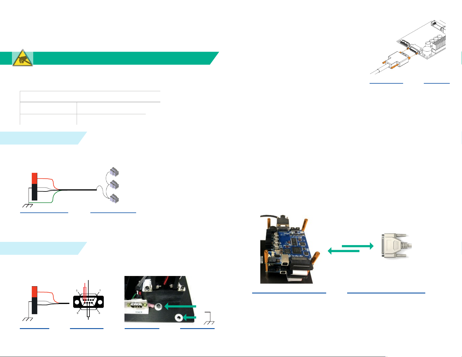
STEP 4: Verify Proper Grounding
Before connecting your controller to the Lightning II scan head, complete the
following:
+48V
GND
0V
CHASSIS GND
Power Cable
Fan
Y-Servo
X-Servo
1. With the Lightning II servo boards and your controller powered on, and your
XY2-100 cable plugged into your controller only, measure the voltage difference
between the servo chassis ground (A) and your XY2-100 cable DB25 (B) connector
shell. The voltage should be less than 0.3V. This verifies that your controller is
properly grounded to the chassis. If you measure >0.3V, do NOT connect XY2-100
cable and contactus. See Figure 5.
Figure 1
3. Connect the daisy-chained power connectors at the other end of the power cable
to the servo boards and fan in the order shown at the right side of Figure 1. Make
sure that the first connector in the chain goes to the X-Servo and the last connector
goes to the fan.
(A)
Figure 5
Corner metal posts
are chassis ground
(B)
Figure 5
2. Make a power cable with a DB9 female connector based on the pin assignments
shown below. Make sure that the GND (White) and 0V (Black) are tied to the Chassis
Ground at the power supply end as shown in Figure 2.
GND
A
B
Voltage
difference
should be
<0.3V.
Figure 5
2. Turn off the power to the scan head and controller.
3. Connect your controller to the XY2-100 interface board via your XY2-100 cable.
The XY2-100 interface board is at the bottom of the Lightning II servo board stack.
Figure 2 Figure 3 4. Apply power to the scan head and controller.
3. Make sure that the servo stack is tied to the system Chassis Ground by one of
the locations (A) or (B) shown in Figure 3.
3-Axis Scan Head
+48V
GND
0V
2-Axis Scan Head
Please wear an ESD strap when performing these steps.
+48V
0V
CUSTOMER POWER
SUPPLY
CUSTOMER POWER
SUPPLY
}
LightningTM II Electrical Specifications
Input Voltage 48 ± 2V DC, Single Power Supply
Power Requirements 6A Peak, 3A RMS per axis
Other Novanta Industrial Equipment manuals


Popular Industrial Equipment manuals by other brands

schmersal
schmersal AZM201Z-CC-T-1P2PW Instructions for operation

STEPCRAFT
STEPCRAFT Touch Probe P100 operating manual

ABB
ABB CC1600-SC55 quick start guide

HyQuest Solutions
HyQuest Solutions HailSens IoT user manual

Pilz
Pilz PSEN 1.1p-22 operating manual

INOXPA
INOXPA ASPIR EX Installation, service and maintenance instructions


