FASTERHOLT B2 Guide

Irrigator
B2
Telephone: +45 97 18 80 66
Telefax: +45 97 18 80 40
E-mail: [email protected]
Web: www.fasterholt.dk
(EN) 21-03-2022
User Manual &
Spare Parts Catalogue
Fasterholt Maskinfabrik A/S
Ejstrupvej 22
7330 Brande
Denmark

2
Contents
EU Declaration of Conformity 3
General Safety 4
Introduction BORDING Type 2-3-4-5TT2 Irrigator 4
Operating instructions 7
Working area 9
Transport 9
Positioning 9
Unwinding the hose 9
Start-up 12
PTO rewind 13
Gun trailer 13
Maintenance 15
Preparation for winter 16
Troubleshooting table 17
Technical data 18
Nelson SR 150 18
Product labelling 19
Symbols used in this product 19
Spare parts 40
Chassis and turntable 40
Rim, tyre and wheel shaft 42
Rim, tyre and wheel shaft (large wheel) 44
Gearbox 46
Low pressure 48
High pressure 54
Turbine 60
Hose guide and emergency stop bar 62
Drum and cover 66
Main bearing and hose 68
Support feet, guards and labels 70
Manual lift 72
Control box, battery, solar cell and labels 74
Gun trailer 78

3
EU Declaration of Conformity
EEC Declaration of conformity
Fasterholt Maskinfabrik A/S
CVR:
58 83 28 12
TEL:
+45 97 18 80 66
FAX:
+45 97 18 80 40
E‑Mail:
mail@fasterholt.dk
Manufacture (name and
address):
Adresse: Ejstrupvej 22,
Fasterholt
Ort: 7330 Brande
Country: Denmark
Web: www.fasterholt.dk
Hereby is certified that the following
product:
Description, ID/mark, type:
Serial No. if any:
Notified body if any:
EEC-type certificate if any:
Harmonised standards if any:
EN 908:1999+A1:2009.
DS/EN/ISO 12100:2011.
DS/EN/ISO 14120:2015.
Is made according to the announcement no.693 of 10. Jun 2013 that implements the
DIRECTIV 2006/42/EC.
Name, title and signature of manufacture:
Date Signature
Irrigator B2

4
Introduction
BORDING Type 2-3-4-5TT2 Irrigator
The BORDING Type 2-3-4-5TT2 is a stationary type irrigator with a hose drum (rewind machine). The hose drum is mounted on a turntable
and equipped with a gun trailer lift, so the unwind direction can be changed without having to move the machine. A turbine is used to
power the machine and rewind stops automatically when the gun trailer reaches the machine.
The machine can also be tted with an automatic pump stop function for high pressure or low pressure. With the high pressure stop
function, make sure that the pump is either switched o via a pressostat or can dispose of water by other means when the machine stops
irrigation. With the low pressure stop function, the pump must be stopped via a pressostat.
It should be noted that this is a eld irrigation machine and that progress is made with water under high pressure, as well as high pressure
from the gun. This means there is a risk of injury if the machine is used inappropriately, so the warnings and safety instructions given here
must therefore be respected and followed precisely.
Make sure that no unauthorised persons have access to the machine during operation.
To get the greatest benet from the machine, it is important that the operating instructions are followed precisely. Only a few levers are
required and they are described in the correct order. After a short period of using the machine, these levers become a matter of course, just
as a last look at the plant in operation is a matter of course.
We must also point out that any damage caused by incorrect operation, use of the machine outside its working area (see the
Working Area section) and/or negligence is not covered by the warranty.
Fasterholt Maskinfabrik only guarantees new machines sold through an authorised Fasterholt dealer and only after the enclosed
start-up list has been reviewed, completed and signed.
In the event of any structural change/modication carried out on the irrigator without the written consent of A/S Fasterholt
Maskinfabrik, we disclaim all liability and the warranty shall be declared void.
In addition, our liability does not cover defects caused by materials obtained by the buyer or by constructions prescribed or
specied by the buyer.
Should a problem occur with the machine or if you have any questions, please contact your Fasterholt dealer.
Best regards,
A/S Fasterholt Maskinfabrik
General Safety

5
General:
It is a prerequisite for handling the irrigator that you read this instruction manual carefully before using the machine. Only allow properly
trained and qualied persons to operate the machine. Only one person (the operator) must be in the vicinity of the machine during
transport, setup, operation and dismantling =”not in operation”.
Denitions:
During transport:
The machine is secured to a vehicle, ready to be transported to the installation site.
During setup:
The machine is placed at the installation site and the hose is unwound and ready to be connected to the water supply.
In operation:
Water/liquid is connected to the machine, which is under pressure or ow, or the machine is operated with a PTO.
Not in operation:
There is no pressure or ow in the machine. Feed water is not connected to the machine. Rewinding is not performed with a PTO.
When the machine is in operation (see denition), only the following operations may be carried out:
1: Adjusting the rewind speed.
2. Changing gear if this is set incorrectly.
Warning: If the hose is in tension when uncoupling, the drum can run back with great force.
Warning: Be careful around the actuator and other moving parts in the electronic control as these continuously regulate the ow of
liquid through the turbine with the risk of crushed arms, hands and ngers.
Warning: Climbing on or under the machine when it is in operation may result in fatal injury.
All other adjustments to the machine, gun trailer and gun should only be made when
the machine is “not in operation”.
In the following instruction, warnings that concerning your safety are marked with the following label. These labels are also found on the
machine where they present a danger. Be careful, therefore, whenever you see this label:
Warning:
Read the warning every time you see the label.

6
2TT2 3-4-5TT2
Pos 1 .................................................... Lever for turntable X X
Pos 2 .................................................... Locking pawl for turntable X X
Pos 3 .................................................... Support leg X X
Pos 4 .................................................... Valve X
Pos 5 .................................................... Water supply at low pressure X
Pos 6 .................................................... Water supply at high pressure X
Pos 7 .................................................... Lever for support leg X
Pos 8 .................................................... Water supply X

7
Operating instructions
2TT2 3-4-5TT2
Pos 1 ...................................... Sliding bushing X X
Pos 2 ...................................... Lubrication nipple for sliding bushing X X
Pos 3 ...................................... Battery X X
Pos 4 ...................................... Actuator X X
Pos 5 ...................................... Safety cable X X
Pos 6 ...................................... Best one X X
Pos 7 ...................................... Gear lever X X
Pos 8 ...................................... Coupling lever X X
Pos 9 ...................................... Oil level check X X
Pos 10..................................... Oil drainage X X
Pos 11..................................... PTO shaft X X
Pos 12..................................... Brake X X
Pos 13..................................... Gear chart X X
Pos 14..................................... Rainfall chart X X
Pos 15..................................... Main chain X X
Pos 16..................................... V-belt X X
Pos 17..................................... Chain for hose guide X X
Pos 18..................................... Chain tensioner, hose guide X X
Pos 19..................................... Chain tensioner, main chain X X
Pos 20..................................... Belt tensioner X X
Pos 21..................................... Actuator for stop valve X X
Pos 22..................................... Buttery valve X

8

9
Working area
The working area of the machine is the application of water, waste water and other liquids, with a dry matter content not exceeding 15%.
Particles in the liquid must not exceed 10 mm, as this would clog the machine turbine.
The machine must be supplied with a maximum pump pressure of 12 bar. The recommended working pressure is 7-9 bar.
Transport
When moving the machine or transporting it into the eld, attach it to a hollow bar in the tractor’s lifting arms and use the tractor’s own lift
to raise and lower the machine.
1. Rotate the drum so the gun trailer is facing backwards.
2. Raise the support leg into the transport position.
3. If the machine is not tted with brakes, the speed must not exceed 6 km/h.
Note: If the machine is to be transported on public roads, it must be tted with lights and markings.
Important: The coupling lever must be engaged during transport to prevent the hose from become loose on the drum.
Positioning
1. Position the machine horizontally in line with the unwind direction.
2. The ground must be level for the rst 10 m of the unwind direction.
Warning: It is forbidden for unauthorised persons to stand alongside the machine while manoeuvring the gun trailer
and machine.
Unwinding the hose
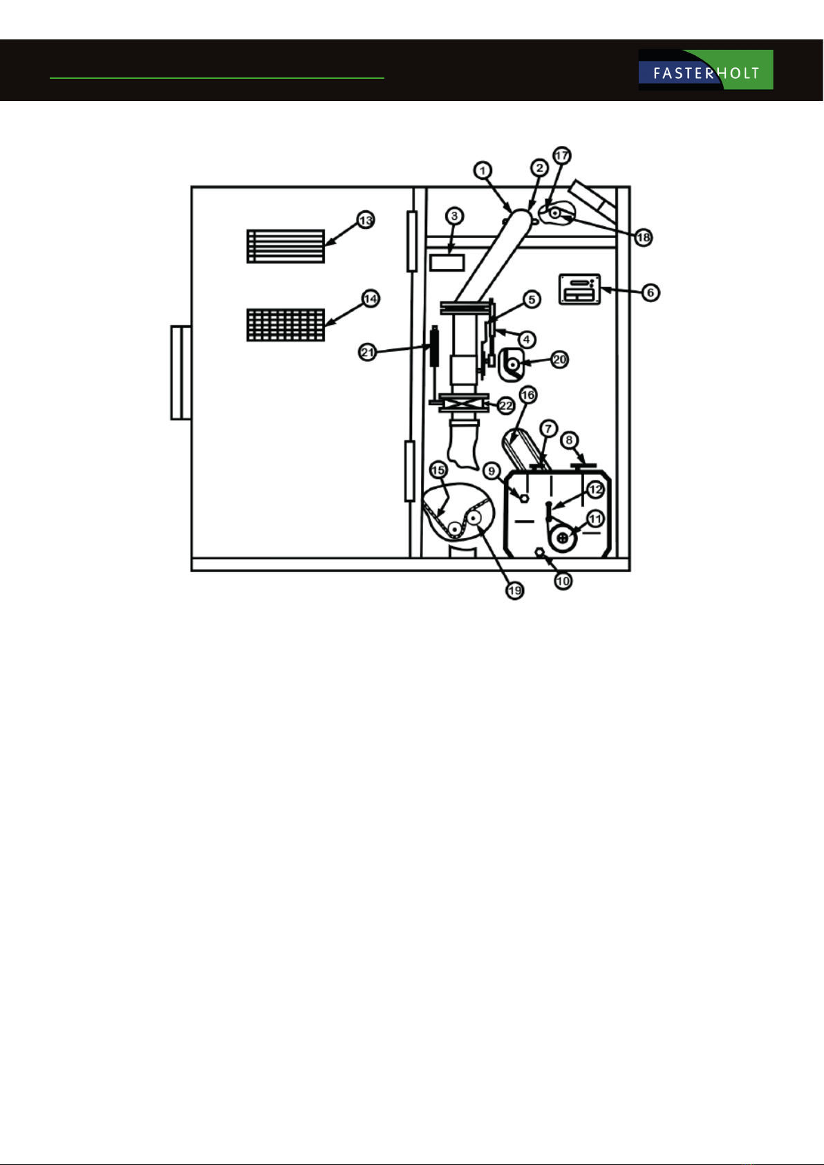
1. Loosen the locking pawl at the toothed rim (Fig. 2, Pos 1)
2. Rotate the drum in the desired direction.
3. Lock the locking pawl (Fig. 2, Pos 1)
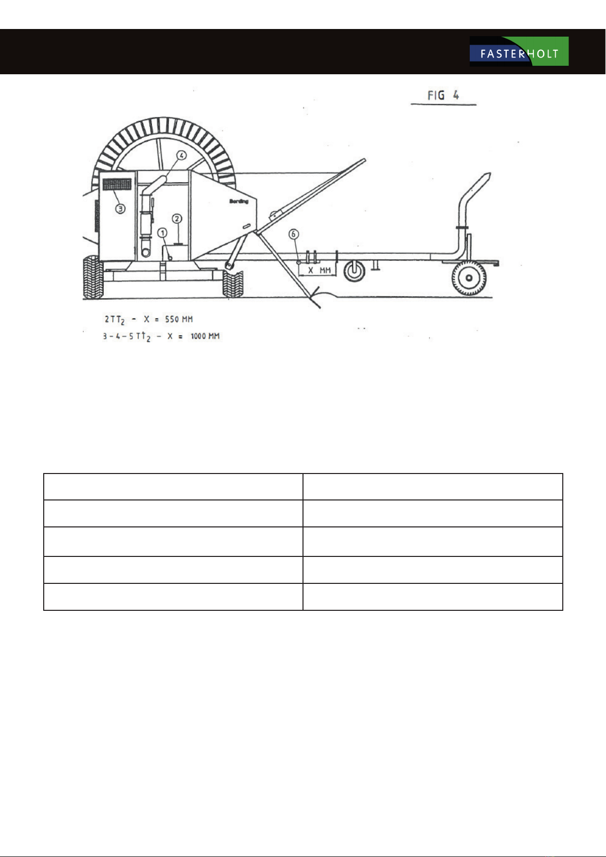
4. Lower the support leg and push it into the ground (Fig. 3, Pos 2). For type 3-4-5 TT2, use the levers in the cover.
5. Lower the gun trailer and release it from the lift. On machines with hydraulic support legs, the gun trailer lowers automatically.
6. Open the valve under the gun trailer (Fig. 2, Pos 2) (only for types 3-4-5IT2.)
7. Move the coupling lever to “NEUTRAL” (Fig. 3, Pos 3)
8. Connect the tractor to the gun trailer and unwind it - max. 3 km/h.
9. The feed hose should not be connected during unwinding.
If the water has not started to ow out of the machine after about 10 metres, it may be benecial to stop unwinding for a moment and start
again (applies to 3-4-5TT.)
Important: Never unwind the hose too far – always ensure that there are at least 2 hose turns left on the drum, otherwise the hose
coupling will be damaged when the hose is rewound.
Driving on hilly terrain may require an assistant.
Note: If the hose temperature exceeds 30 degrees due to the machine being in sunlight or otherwise exposed to heat, cool it
by ushing water through the hose before unwinding it, otherwise it may be damaged.
When unwinding the hose, it is important to avoid suddenly stopping the tractor, as the hose may tangle on the drum.
If the hose becomes loose on the drum during unwinding, adjust the drum brake (Fig. 4, Pos l). If the hose is loose on the drum when fully
unwound, tighten it with the PTO crank handle, found in the cover. Remember to remove the PTO crank handle after tightening.

10
GEAR SPEED M/H
1 7 - 20
2 15 - 45
3 25 - 65
4 40 - 100
POS 3

11

12
Start-up
Important before starting the machine!
If exposed to sunlight, the hose may become hot. Check that the hose is not above 30 degrees before starting. If the hose is too hot, cool it
rst by ushing water through it.
1. Engage the coupling lever (Fig. 4, Pos 2)
2. Select the gear from the table located inside the cover (Fig. 4, Pos 3).
3. Enter the rewind speed on the computer using the arrow keys (see section under Rainfall.)
4. For pre-irrigation, press Pre (highlighted in display.)
5. For post-irrigation, press Post (highlighted in display.)
6. Connect the feed hose.
7. Press start.
8. Open the hydrant and start the water supply pump.
Note: The pump must be started within the supervision time (factory set at 20 minutes).
See also “PR 10-12” User Instruction for further programming options.
Warning: It is forbidden to climb on or under the machine during operation.
Rainfall
Once the rewind speed, nozzle type, nozzle size and nozzle pressure are known, the rainfall can be read in the tables. The nozzle pressure
can be read on the gun manometer. The table shows the maximum eective spreading widths in calm weather. In windy conditions, it will
drop by about 10%.
Setting the gun:
The operating pressure of the gun should be 3.5 - 4.5 bar depending on the type of gun and the water volume.
For high water volumes, the pressure should be higher.
The best spreading width is achieved at a sector angle of approx. 200 degrees. This means that the gun operates over an angle of 200
degrees.
Rewind direction
Automatic stop
Rewind stops automatically when the gun trailer is wound back into the machine and the stop buer hits the hose guide. The machine is
tted with high pressure or low pressure stops.
At high pressure stop, switch o the water supply to the machine and make sure that the pump either stops via a pressostat or can dispose
of water by other means.
At low pressure stop, open the buttery valve to allow some water through, the pressure will drop and the pump will stop via a pressostat.
If high pressure or low pressure is changed, contact your Fasterholt dealer.
Stop buer
Mount the stop buer on the hose using two hose clamps (Fig. 4, Pos 6.)

13
Manual stop
The machine can be stopped either at the pump or by pressing “STOP” on the computer.
If the hose is to be rewound after stopping, see the section PTO rewind.
Safety stop
The safety bar on the rewind side of the machine ensures that the machine stops when the hose is wound incorrectly. The safety cable
ensures that the machine stop will in case of computer failure. Adjust the safety bar until it is 1 cm from the drum edge. Adjust the cable so
it is tight when the three-way valve is fully open (max. speed.)
Important: When starting for the rst time, check that the safety bar and cable are adjusted correctly.
Supervision
The computer monitors the machine to ensure that it stops correctly if the rewind stops prematurely.
E.g.
1. Machine is not in gear
2. Foreign objects in the turbine
3. V-belt is too slack
PTO rewind
The machine is equipped with a PTO rewind, which is used to manually wind up the hose if irrigation is stopped before the gun trailer is
inside the machine.
The PTO rewind is connected to the tractor via a PTO shaft (power transmission shaft.)
1. The coupling lever must be disengaged before starting to rewind.
2. Apply the tractor’s hand brake.
3. Max. PTO speed is 200 rpm.
4. Stop the PTO rewind approx. 2 m before the gun trailer is inside the machine and use the PTO crank handle (located in the
cover) for the last section.
Important:
Remove the PTO crank handle during operation.
The PTO shaft must not be on the machine during operation.
The machine must be supervised when the hose is rewound onto the drum via the PTO rewind.
Warning: If the machine is stopped during rewind, the hose is in tension and the drum may run backwards when the clutch lever
is released.
It is forbidden to climb on or under the machine during operation.
Gun trailer
The gun trailer can be adjusted with dierent track widths by loosening the tensioning lever (Fig. 8, Pos 1). The gun trailer can also be
displaced sideways by loosening the two tension bars (Fig. 8, Pos 2).
If the gun trailer does not follow the same track during rewind as during unwind, loosen the centre bolt on the steering wheel (Fig. 8, Pos 3)
and move the wheel axle back and forth on one side by turning the steering wheel.

14

15
Maintenance
Important: After the rst 25 operating hours:
1. Retighten the machine.
2. Adjust the chains and V-belts.
3. Adjust the hose guide.
After 25 hours of operation, it may be necessary to adjust the hose guide. The hose guide must lay each hose turn tightly up against the
previous hose turn (see Fig. 5). If the situation is as shown (Fig. 6), it will be necessary to adjust the hose guide.
Adjustment:
Stop the machine, loosen the chain tensioner (Pos 1) and lift the chain o the chain wheel. You can now pull the chain back or forth by
hand, so the hose guide will move to either side.
Move the hose guide in this way so that the hose section that is engaged comes onto the drum and overlaps the rewound hose by 5-10
mm. When this condition is reached, put the chain back on the chain wheel and tighten it. The hose guide is now correctly adjusted. The
adjustment should be made when the hose is wound on the inner layer. Turn the drum a few times to check that the hose is tted correctly.
Lubrication: (after 25 operating hours) and weekly thereafter
Lubricate the sliding bushing on the drum inlet pipe (Fig. 4, Pos 4).
Lubricate the cross track shaft.
Lubricate the guide rail for the hose guide.
Lubricate the main bearing on the drum.
Lubricate the wheels on the gun trailer.
Lubricate the turntable.
We recommend Molykote grease for lubrication of the above parts.
Lubricate chains with water-repellent oil.
Note: Stop lubricating the sliding bushing in the inlet bend of the hose drum when there is a slight increase in pressure in the grease gun.
Annual maintenance
Lubricate the sliding bushing on the drum inlet pipe (Fig. 4, Pos 4).
Lubricate the cross track shaft.
Lubricate the guide rail for the hose guide.
Lubricate the main bearing on the drum.
Lubricate chains.
Lubricate the wheels on the machine and gun trailer.
Lubricate the turntable.
We recommend Molykote grease for lubrication of the above parts.
Note: Stop lubricating the sliding bushing in the inlet bend of the hose drum when there is a slight increase in pressure in the grease gun.
Lubricate the damper in the three-way valve with water-repellent grease (KLOBER NBU 30 PTM.)
Change oil in the gearbox. Oil type Castrol EPX 80/90 gear type or equivalent.
Check the air pressure in the wheels: Machine = 38 psi - 2.75 bar
Gun trailer = 14 psi - 1 bar

16
Preparation for winter
Before the frost sets in, prepare the machine for winter. Contact your BORDING dealer to request a winter service visit. This avoids
unnecessary downtime during the season.
Preparation includes the following points:
The machine and hose must be drained of water either by compressed air or by unwinding the hose into the eld and rewinding it with the
PTO rewind. (Disconnect the gun trailer.)
Note: The buttery valve must be open.
Do not rewind the hose tightly as the hose must be able to operate at dierent temperatures.
This is done by loosening the hose slightly with each layer using the PTO crank handle during rewind.
Clean the gun and inject acid-free oil.
Lubricate and adjust chains.
Check the air pressure in the wheels: Machine = 38 psi - 2.75 bar
Gun trailer = 14 psi - 1 bar
Lubricate the three-way valve.
Lubricate all moving parts with anti-corrosion oil (LPS oil).
Remove the battery and store it fully charged in a dry, frost-free environment.
Important:
Avoid high pressure cleaning of computers, electrical components and packing blocks in bearings.

17
Troubleshooting table
Error Cause Solution
Drum stop Foreign object in turbine Remove front cover from
turbine and clean.
Never use force to turn the
turbine.
Clutch lever not engaged Engage lever
Computer failure Check computer
Three-way valve is stuck Check three-way valve
Computer error Battery at Charge or replace
Stop sensor on stop bracket activated Adjust or replace
Control error Contact your dealer
Actuator not running Damper in the three-way valve is stuck Clean and lubricate the
damper
Actuator not working Computer fault or replace
actuator
Rewinding error Hose guide out of alignment Adjust the hose guide
Too much hose on drum Check hose length
Unwinding error
(hose loose)
Brake loose Adjust brake
Stops too quickly when unwinding Reduce speed over a longer
distance
Hose guides do not move Chain jumped o Repair/Replace
Guide pin faulty Replace
Gun does not work Pressure too low Increase pressure or switch to
smaller nozzle
Sector guide damaged Replace/repair stop trigger
Incorrect nozzle size Replace nozzle

18
Nelson SR 150 is factory-adjusted to Danish conditions and ready to use after the following three steps:
1. Select and install the nozzle size that best suits your application. Performance data for the dierent sizes are shown in the table below.
2. Adjust the stop on the part circle to obtain the desired irrigation angle.
3. There is a grease nipples which should be checked once a week for relling.
ADJUSTMENT
The only thing you can adjust is the counterweight on the drive arm.
By moving the counterweight forward, the gun will slowly irrigate from side to side.
If you move the counterweight back, the gun will irrigate quickly. If it does not irrigate quickly enough, you can
remove the brake springs (no. 778474) in pairs (contact the service department).
WARNING: DO NOT ADJUST WHEN THE GUN IS IRRIGATING !! DANGER: HIGH WATER PRESSURE –
STAY CLEAR !!
TABLE FOR NELSON SR 150
Technical data

19
Symbols used in this product
The following symbols are used in this product and the following documentation.
WARNING Indicates a potentially dangerous situation which, if not prevented, could result in death or serious inju-
ry.
LUBRICATION Indicates lubrication is required as per the service description.
SERVICE WARNING Indicates a service hazard
SMØRING
Str: 100x45 mm
HUSK efterspænding
af hjulbolte
Str: 69x20 mm
Product labelling

20
Functions:
Speed regulator
Pre- and Post-irrigation
4 dierent speeds on sections of the lane
Clock
Setting the start time
Stop time is shown on the display
Length of hose
Current speed
Battery volts
Charge regulator
Pressure sensor
Stop sensor
Speed sensor
Motor 1, regulating motor
Motor 2, stop motor
Slow start of turbine
Slow closing of inlet
Water volume + spreading width
Accessories:
GSM, SMS messages for remote control.
Analogue pressure sensor.
Table of contents
Other FASTERHOLT Farm Equipment manuals

FASTERHOLT
FASTERHOLT FM2500 Installer manual

FASTERHOLT
FASTERHOLT FM4400 User manual

FASTERHOLT
FASTERHOLT FM4550 Installer manual

FASTERHOLT
FASTERHOLT GT12 Installer manual

FASTERHOLT
FASTERHOLT FM4800H Installer manual

FASTERHOLT
FASTERHOLT FM4400 Installer manual

FASTERHOLT
FASTERHOLT FM4400H Installer manual
Popular Farm Equipment manuals by other brands

Susteco
Susteco BIGHANNA T40 Operation manual

Lemeks
Lemeks Palmako Chick EL16-2132 Assembly, installation and maintenance manual

MASSEY FERGUSON
MASSEY FERGUSON MF 1800 Operator's manual

Spearhead
Spearhead Outfront Flail 130 Handbook & Parts Manual

AGI WESTFIELD
AGI WESTFIELD MKX 13 Series Assembly manual

aivituvin
aivituvin AIR 52 instruction manual