FASTERHOLT GT12 Installer manual

Irrigator
GT12 ENG
Telephone: +45 97 18 80 66
Telefax: +45 97 18 80 40
Email: [email protected]
Web: www.fasterholt.dk
(EN) 21-04-2021
User Manual &
Spare Parts Catalogue
Fasterholt Maskinfabrik A/S
Ejstrupvej 22
DK-7330 Brande
Denmark

2
Contents
Declaration of Conformity 3
General safety 4
Operating Instructions & Information 4
Product labelling 5
Symbols used in this product 5
Intended use 6
Nelson SR150 6
Operating instructions 7
Starting your irrigator 7
Setting up the Gun trailer 10
Start-up 11
Maintenance 12
Preparation for winter 12
Troubleshooting table 14
Spare parts 36
Hose drum 38
Chassis 40
Gearbox 50
Chassis 54
Pendulum Gun trailer 58
Standard Gun trailer 68

3
Declaration of Conformity
EEC Declaration of conformity
Fasterholt Maskinfabrik A/S
CVR:
58 83 28 12
TEL:
+45 97 18 80 66
FAX:
+45 97 18 80 40
E‑Mail:
mail@fasterholt.dk
Manufacture (name and
address):
Adresse: Ejstrupvej 22,
Fasterholt
Ort: 7330 Brande
Country: Denmark
Web: www.fasterholt.dk
Hereby is certified that the following
product:
Description, ID/mark, type:
Serial No. if any:
Notified body if any:
EEC-type certificate if any:
Harmonised standards if any:
EN 908:1999+A1:2009.
DS/EN/ISO 12100:2011.
DS/EN/ISO 14120:2015.
Is made according to the announcement no.693 of 10. Jun 2013 that implements the
DIRECTIV 2006/42/EC.
Name, title and signature of manufacture:
Date
Signature
Irrigator GT 12

4
IMPORTANT!
Read this manual carefully before using
your irrigator!
Your new Fasterholt irrigator is a high quality,
Danish built machine, but even the best
machines only deliver top results when they are
properly handled and maintained.
To ensure that the machine complies with the
EU Machinery Directive, only original spare
parts may be used. Otherwise, compliance will
be lost and safety will be entirely at your own
risk.
The irrigator is only suitable for irrigation
with clean water from a drilled well or a
watercourse.
We must point out that any damage caused
by incorrect operation and/or negligence
is not covered by the warranty. Fasterholt
Maskinfabrik A/S only guarantees new
machines sold through an authorised Fasterholt
dealer. Any modifi cations made to the design
of the irrigator shall exclude Fasterholt
Maskinfabrik A/S of any liability and shall void
the warranty.
The Fasterholt FM GT12 is a stationary type
irrigator with a hose drum (rewind machine).
The hose drum is mounted on a turntable and
equipped with a gun trailer lift, so the unwind
direction can be changed without having to
move the machine. A turbine is used to power
the machine and rewind stops automatically
when the gun trailer reaches the machine.
The machine is available with an underpressure
stop or an overpressure stop. With the
overpressure stop function, make sure that the
pump is either switched off via a pressostat
or can dispose of water by other means
when the machine stops irrigation. With the
underpressure stop function, the pump must be
stopped via a pressostat.
The machine must be supplied with a maximum
pump pressure of 12 bar. The recommended
pressure 7-9 bar.
Safety instructions/warnings
If the machine is to be moved via a public
road, the machine must fi rst be emptied of
water.
As this machine is used for fi eld irrigation
involving high water pressure, there is
a risk of injury if the machine is used
inappropriately. The warnings and safety
instructions given here must therefore be
respected and followed precisely.
- It is forbidden to stand on the machine
during irrigation and transport. (risk of
fatal injury)
- The guards are fi tted for your own safety -
please leave them in place
- Remember to tighten the wheel bolts
- During transport on uneven roads/fi elds,
move VERY carefully according to the
conditions.
- DANGER! Avoid welding in the paint layer!
Before welding, remove all paint from the
welding area
- Only one person (the operator) should
be in the vicinity of the machine during
transport, setup and dismantling
WARNING: If the machine is
stopped during rewind, the hose is
in tension and the drum may run
backwards when the clutch lever is
released.
Operating Instructions & Information
General safety

5
The following symbols are used in this product and the following documentation.
WARNING Indicates a potentially dangerous situation which, if not
prevented, could result in death or serious injury.
LUBRICATION Indicates lubrication is required as per the service
description
SERVICE WARNING Indicates a service hazard
Symbols used in this product
SMØRING
Str: 100x45 mm
HUSK efterspænding
af hjulbolte
Str: 69x20 mm
Product labelling

6
1. Select the nozzle size that best suits your application and install it. Performance data
for the diff erent sizes are shown in the table below.
2. Adjust the stop on the part circle to obtain the desired irrigation angle.
Adjustment:
The only thing you can adjust is the counterweight on the drive arm. By moving the
counterweight forward, the gun will slowly irrigate from side to side. If you move the
counterweight back, the gun will irrigate quickly. If it does not irrigate quickly enough, you
can remove the brake springs in pairs. (Contact the service department).
WARNING: DO NOT ADJUST WHEN THE GUN IS IRRIGATING!
HIGH WATER PRESSURE – STAY CLEAR!
Nelson SR150
Intended use

7
1. Position the machine horizontally in line with the unwind direction.
2. The ground must be level for the fi rst 10 m of the unwind direction.
3. Connect the two hydraulic hoses to the tractor.
4. Rotate the drum in the desired direction.
Rear
support leg
Front
support leg
For hydraulic
turntable
It is important that the machine is level.
This can be adjusted with the support legs
at the front and rear.
Operating instructions
Starting your irrigator
8
5. Lower the two hydraulic support legs to the ground so they are fi rmly engaged. If
the ground is very hard, it may be necessary to move them up and down a few times.
(Warning!! The support legs must not raise the wheels of the machine from the
ground.)
6. The gun trailer lowers automatically when the support legs are lowered.
7. If the machine is equipped with a high pressure/low pressure function, ALWAYS REMEMBER
to press start before fl icking the toggle switch to the desired stop function.
Høj tryk Lav tryk
Lever in this position when
turning the machine.
Lock for fth wheel.
Used during transport
and irrigation.
Mark indicates
chassis position
for road transport.

9
Move the lever on the left hand side to unwind. See the photo below.
Open the slide valve on the gun trailer to allow the water to fl ow freely from the hose
during unwinding. It is important that the feed hose is not connected to the machine until
the hose is fully unwound.
For irrigation, move the lever
in the direction of the arrow.
To unwind, move the clutch release
lever in the direction of the arrow.
Gear selector
Before irrigation, move
the lever in the direction
of the arrow.
To unwind, press the
lever in the direction
of the arrow.

10
REMEMBER when unwinding the hose to ensure that the gun trailer lift is adjusted
correctly. And remember to make sure the machine is standing on fi rm ground, otherwise
damage may occur to the gun trailer lift and machine.
Connect the gun trailer to the tractor and start unwinding the hose. The unwinding speed
must not exceed 3 km/h.
If the water has not started to fl ow out of the machine after about 10 metres, it may be
benefi cial to stop unwinding for a moment and start again.
It is important that the gun trailer is unwound in line with the machine for the fi rst 10
metres of unwinding, as excessive movements may prevent the gun trailer from entering
the gun trailer lift.
WARNING: Never unwind the hose too far – always ensure that there are at
least 2 hose turns left on the drum, otherwise the hose coupling will be damaged
when the hose is rewound. Driving on hilly terrain may therefore require an
assistant or a warning lamp, which can be purchased separately.
WARNING: If the hose temperature exceeds 30 degrees, e.g. due to the machine
being in sunlight, cool it by ushing water through the hose before unwinding
it, to avoid damage to the hose. Unwind the machine 2-5 metres to activate the
limit stop sensor. This to stop water from passing through.
When unwinding the hose, it is important to avoid suddenly braking/stopping the tractor,
as the hose may tangle on the drum. Instead, slow down gently and stop.
If the hose becomes loose on the drum during unwinding, adjust the drum brake. If the
hose is loose on the drum when fully unwound, tighten it with the PTO crank handle.
REMEMBER to remove the PTO crank handle after tightening. Never place the crank
handle on the machine's PTO input during unwinding or operation. Never release/put the
clutch lever in neutral position when the crank handle is on the machine's PTO input and
the hose is in tension.
When the hose is fully unwound, close the slide valve of the gun trailer again.
Setting up the Gun trailer

11
Gear Speed m/h
1 7 20
2 15 45
3 25 65
4 40 200
1. Enter the rewind speed on the computer using the arrow keys.
2. Select the gear according to the table below. (Table is also in the machine cabinet)
1. For pre-irrigation, press "PRE" (highlighted in display). For post-irrigation, press "POST"
(highlighted in display).
2. Connect the feed hose.
3. Press "START".
4. Open the hydrant and start the water supply pump. The water must not be fed too quickly
into the machine to prevent air in the machine, hose and pipe. This can cause pressure
surge and kickback in the system.
WARNING:
• If the hose is in tension when uncoupling, the drum can run back with great
force.
• All other adjustments to the machine, gun trailer and gun should only be made
when the machine is not in operation.
Automatic and manual stop
Rewind stops automatically when the gun trailer is wound back into the machine, thereby
aff ecting the stop bracket. The machine stops due to either overpressure or underpressure.
The machine can also be stopped either at the pump or by pressing "STOP" on the computer.
Emergency stop and safety stop
The safety cable ensures that the machine will stop in case of computer failure.
The machine is equipped with a rewind error bracket that stops rewind if the hose guide
should come out of alignment, causing the hose to tangle. The rewind error bracket will
activate the stop bracket when the reel comes off the edge of the drum.
REMEMBER when starting for the fi rst time, to check that the rewind error bracket and cable
are adjusted correctly.
Gun trailer and hose guide
The gun trailer can be adjusted with diff erent track widths. This is done by loosening the
locking bolts on the chassis and extending the legs to the desired track width.
If the gun trailer does not follow the same track during rewind as during unwind, loosen the
centre bolt on the steering wheel and move the wheel axle back and forth on one side by
turning the steering wheel.
The hose guide ensures that the hose is wound properly on the drum. If the hose does not
wind properly on the drum, the hose guide should be adjusted. The hose must be unwound
until there are two to three turns left on the drum. Remove the hose guide chains and adjust
the hose guide so the hose passing through the hose guide is against the hose already on the
drum. (Contact the service department at Fasterholt Maskinfabrik A/S)
Start-up

12
After winding for the fi rst time, you should:
1. Retighten the machine.
Weekly:
1. Lubricate the sliding bushing on the drum inlet pipe. Stop lubricating the sliding bushing in
the inlet bend of the hose drum when there is a slight increase in pressure in the grease
gun.
2. Lubricate the main bearing on the drum.
3. Lubricate the slide for the hose guide. The axle must never be dry.
4. Lubricate the fl oor reel for the hose guide.
5. Lubricate the wheels on the gun trailer.
6. Lubricate the turntable.
7. Grease the gear wheel on the drum.
Annually:
In addition to the above, the following should be performed annually:
1. Check the oil level in the reduction gear after every 200 hours of operation. If necessary,
top up with type 80/90 gear oil or equivalent.
2. Check the air pressure in the wheels.
On machine: 40psi (2.7 bar)
On gun trailer: 45psi (3.3 bar)
Before the frost sets in, prepare the machine for winter. Contact Fasterholt Maskinfabrik A/S
for a winter service inspection. This avoids unnecessary downtime during the season.
Preparation includes the following points:
1. Drain water from the machine and hose with compressed air. Open the slide valve on the
gun trailer. Note: Butterfl y valve MUST be open.
2. Grease the slide shafts on the hose guide.
3. Clean the gun and inject acid-free oil.
4. Check the air pressure in the wheels.
5. Lubricate all moving parts with anti-corrosion oil.
6. Remove the battery and store it fully charged in a dry, frost-free environment.
See the photos on the following page for frost protection.
Maintenance
Preparation for winter
13
Open the tap for frost protection.
Remove the hose for
frost protection.

14
Error Cause
Foreign object in turbine Remove front cover
and clean turbine.
Clutch lever not engaged Engage lever
Computer failure Check computer
3-way valve is stuck Check 3-way valve
Charge or replace
Stop sensor on stop
Adjust or replace
Fuse in computer Replace fuse
Control error Contact dealer or
Fasterholt Maskinfabrik A/S
Hose guide out of alignment Adjust the hose guide
Too much hose on drum Check hose length
Brake loose Adjust brake
Stops too quickly
when unwinding
Reduce speed
over a longer distance
Pressure too low Increase pressure or
switch to smaller nozzle
Sector guide damaged Replace/Repair stop trigger
Troubleshooting table

15

16
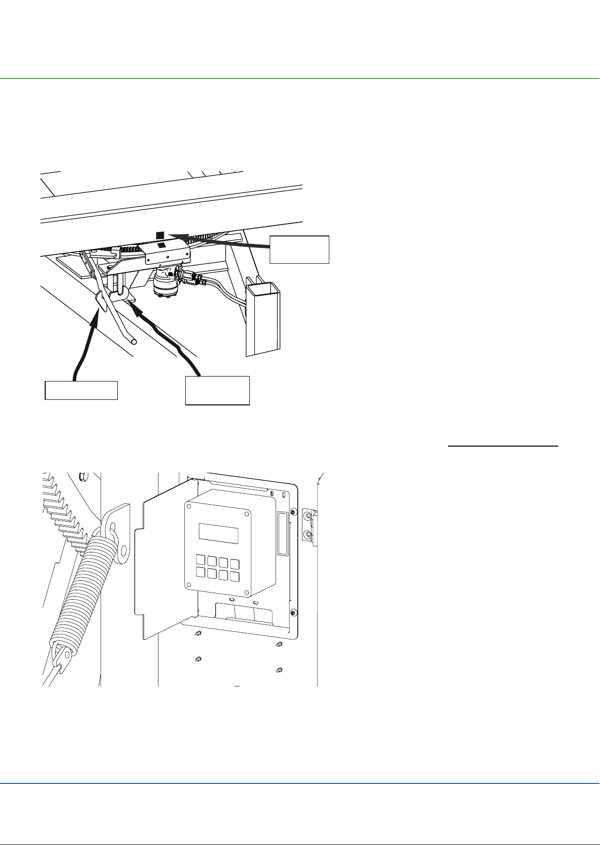
Speed regulator
Clock
Length of hose
Current speed
Charge regulator
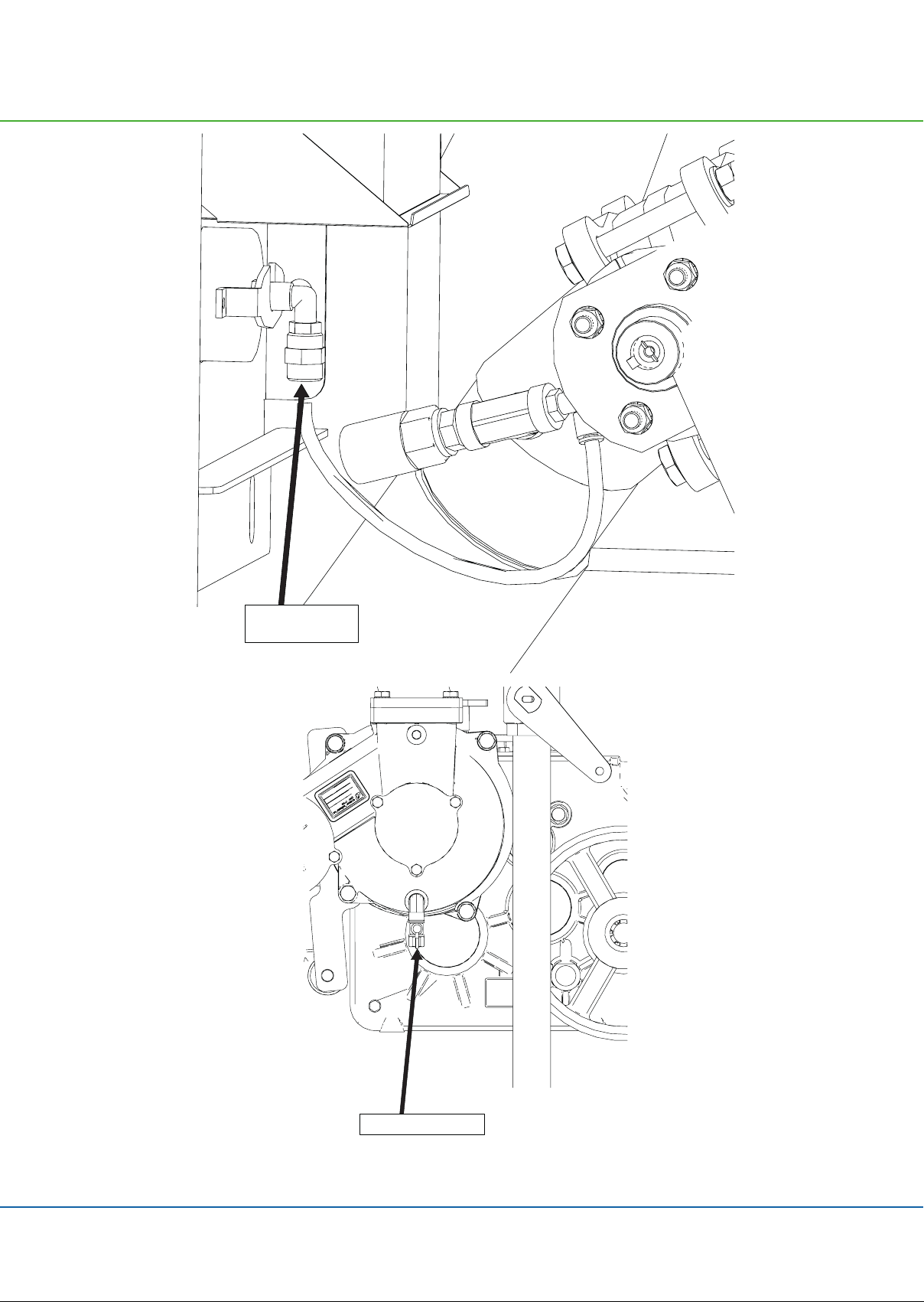
Pressure sensor
Stop sensor
Speed sensor
Motor 2, stop motor
Slow start of turbine
Slow closing of inlet
Water volume + spreading width
GSM, SMS messages for remote control.
Analogue pressure sensor.
17
Pull hose out to end of the lane. ( ex 250 m )
later.
Press START to start. Press PRE and POST for pre- and post-
starts.
machine is now ready to be moved to a new lane.

18
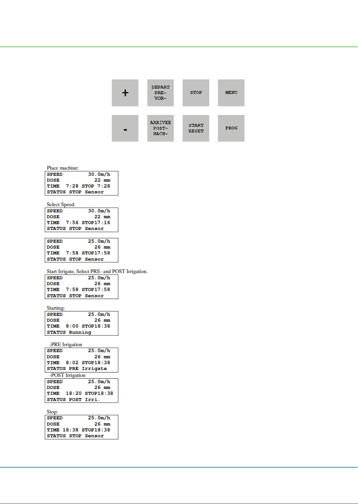
Standard display
Press the
Press the
Press the
Press the
Press the
(Only if GSM is selected)
(Only if GSM is selected)
When

19
Standard display
SPEED
ZONE
DOSE
TIME
STOP
STATUS
The dose is calculated from the speed and constants and shows the current number of mm
PROG
PROG
<
<
<
<
<
LOW BATTERY
LOW BATTERY
be charged.
be charged.
BATTERY
PRE
POST
PROG
PROG
voltage is below 14.0 volts.
PRE-
PRE-
or
or
POST-
POST-
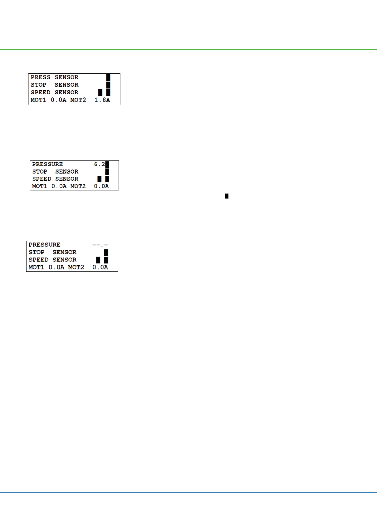
20
Shows that the pressure is high when block is lit.
The machine can only move when the pressure is high.
The machine can only move when the pressure is high.
If no
If no
�
�
�Shows that the magnet is aligned with the stop sensor when block is lit.
�
�
The machine can only start when the magnet is aligned with the stop sensor.
The machine can only start when the magnet is aligned with the stop sensor.
�
�
1.
1.
Reset distance.
Reset distance.
2.
2.
3.
3.
Stop pulses to the regulator motor.
Stop pulses to the regulator motor.
�For the speed sensor test, block is only lit when the magnet passes the sensor.
MOT1, MOT2
�Displays the current motor current. When the current exceeds 4.5 A, the motor stops.
�
�
�Shows pressure in [BAR] (00.0) or [PSI] (000). Pressure is high when is lit.
�
�
The machine can only move when the pressure is high.
The machine can only move when the pressure is high.
�
�
Table of contents
Other FASTERHOLT Farm Equipment manuals


Popular Farm Equipment manuals by other brands

Horst
Horst Contour SHCF36 Operator's manual

HME
HME HM-W0061 Operator's manual

M K Martin Enterprise
M K Martin Enterprise Skid Steer Thirfty Cutter manual

HARRISTON INDUSTRIES
HARRISTON INDUSTRIES 93066 Operator's manual

Sumo
Sumo Seeder quick start guide

Spearhead
Spearhead TWIGA MINI Operator's instruction manual

Toro
Toro Z Master TURBO FORCE Z453 Operator's manual

SteelMax
SteelMax TLB6000 Operator's manual

Harvest TEC
Harvest TEC 493 Installation kit

MacDon
MacDon D65 installation instructions

MacDon
MacDon NEW HOLLAND D2 Series Operator's manual

Xeda International
Xeda International CEDAX ELECTROFOG EWV8 instruction manual


