4
General safety
!!! Important !!!
READ THIS MANUAL BEFORE USING YOUR IRRIGATOR !!
Operating instructions
for Fasterholt FM 4400H
Your new Fasterholt Irrigator is a Danish built machine, but even the
best machines only deliver top results when they are properly used
and maintained.
To ensure that the machine complies with the EU Machinery Direc-
tive, only original spare parts may be used. Otherwise, compliance
will be lost and safety will be entirely at your own risk.
The irrigator is intended for irrigation with clean water from a drilled
well or a watercourse.
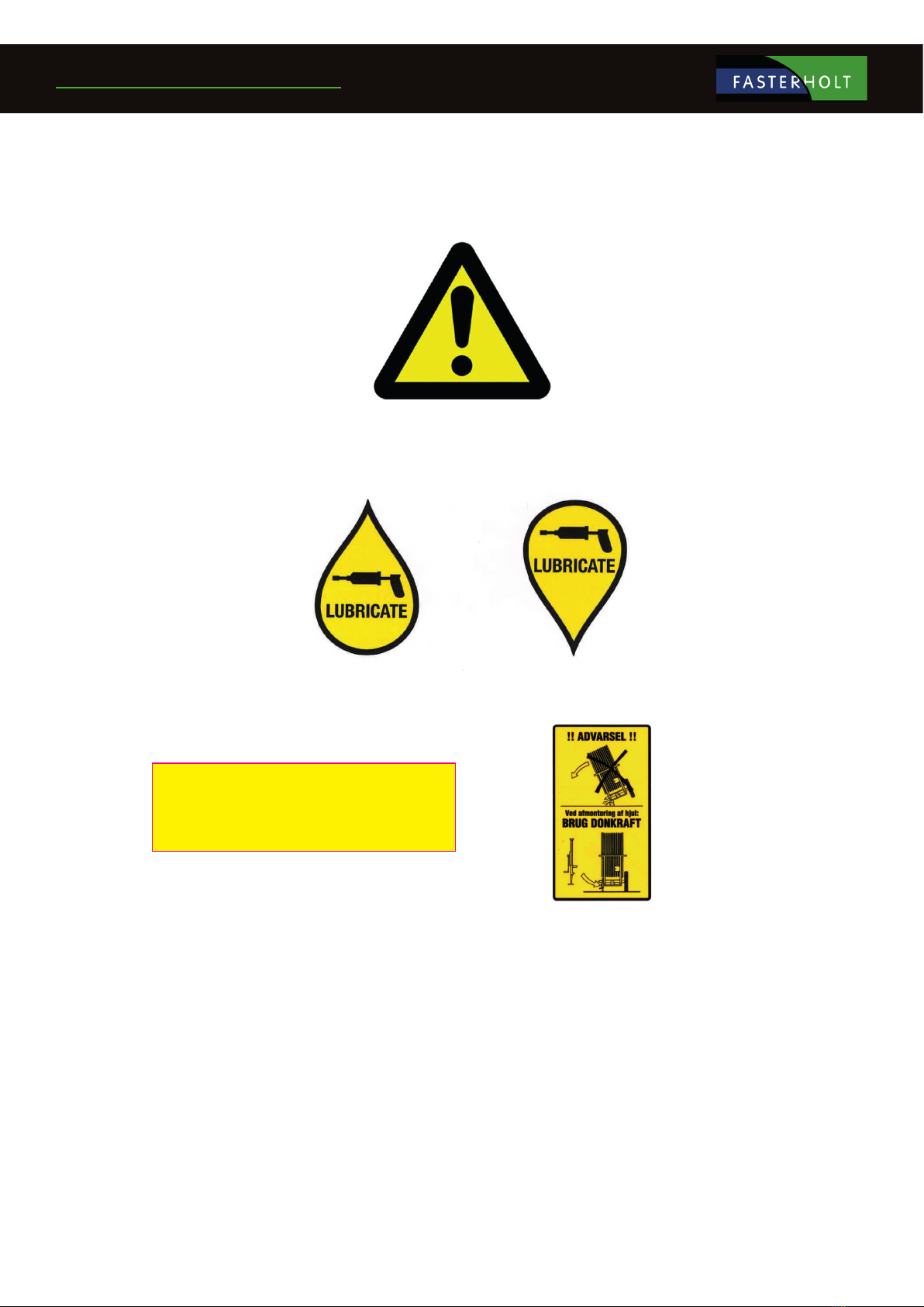
1. Safety instructions/warnings !!
―It is forbidden to stand on the machine during irrigation and
transport
(risk of fatal injury).
―The guards are tted for your own safety - please leave them in
place.
―Remember to tighten the wheel bolts.
―When starting the machine on falling ground, you must be
VERY careful not to disconnect the tractor from the machine
until the machine has been put into gear, otherwise the ma-
chine may run away.
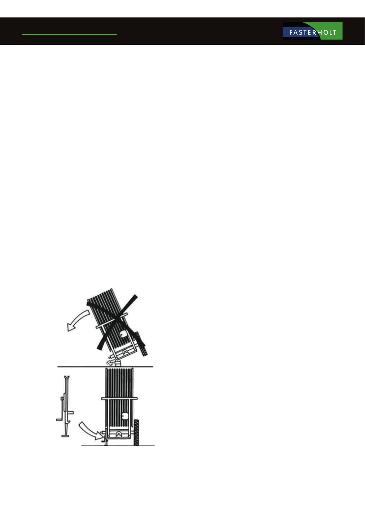
―If a rear wheel is removed, THE MACHINE MUST BE JACKED UP
AND VERY STABLE, because if it overturns, it will fall completely
on its side.
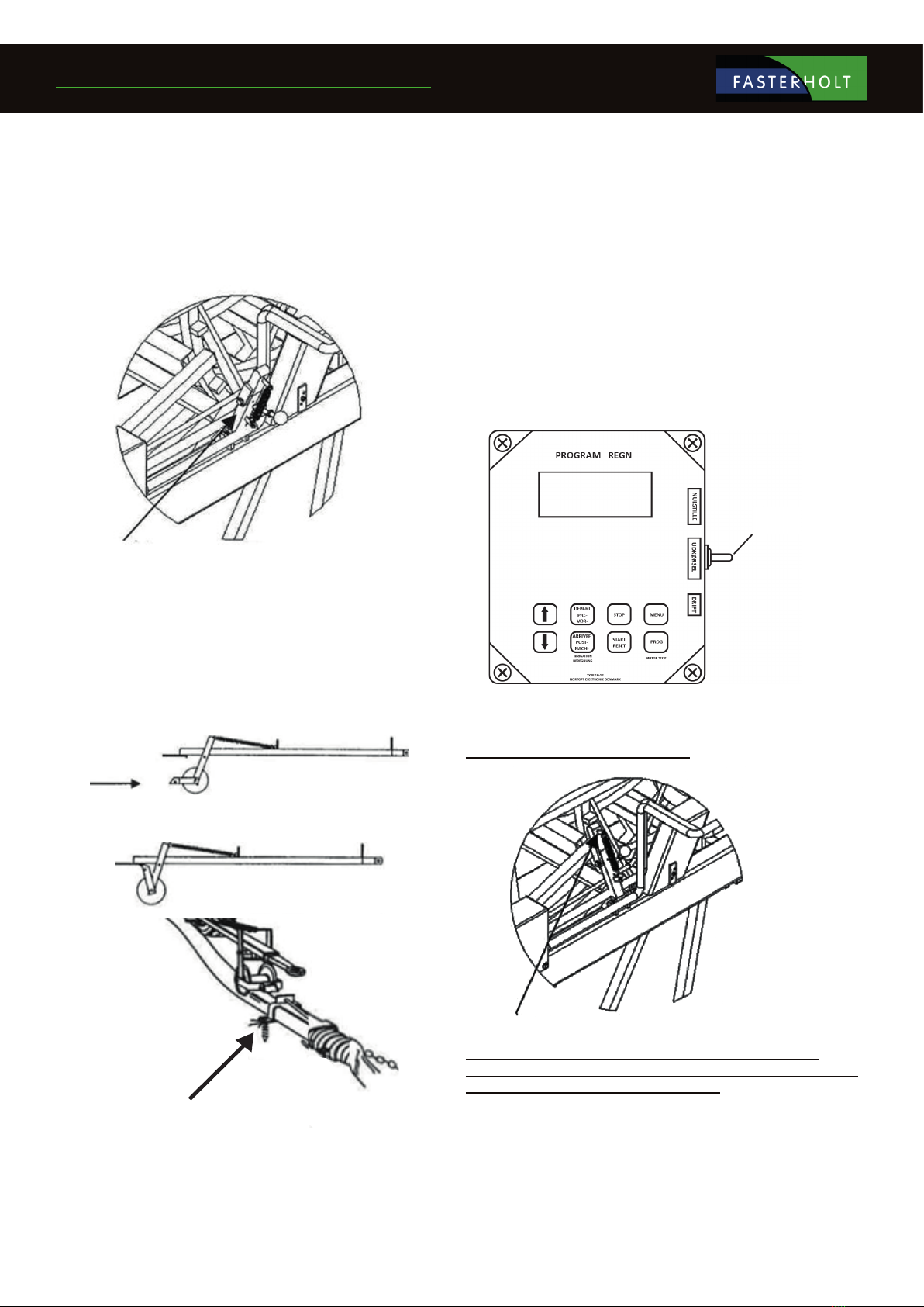
WARNING !!
―To perform an EMERGENCY STOP, pull the cable for the mi-
swinding bar or press STOP on the COMPUTER.
―V-belts may only be tted after the machine has been unwound
for the rst time. (only the rst time the machine is used for
irrigation.)
―The gun must face out to the side when unwinding the ma-
chine.
―STAND ASIDE when the gun is operating.
―WARNING against contact with overhead power lines with the
machine or water jet. Avoid irrigation on or near power lines.
―During transport on uneven roads/elds, move VERY carefully
according to the conditions.
―Max. transport speed with water in the hose is 15 km/h.
―When parking the machine, use the wheel chocks mounted by
the rear wheels.
―DANGER !! Avoid welding in the paint layer! Before welding,
remove all paint from the welding area
―Avoid inhalation of grinding dust.
―Hydraulic oil can be harmful to health:
―Skin contact may cause allergies.
―Inhalation of oil mist may cause lung disease.
―Leakage of oil under high pressure is dangerous, an oil jet can
enter the skin, eyes, etc.
―If a hydraulic system leak is found, stop the system immediately
and rectify the fault.
―Note that due to operation, the oil may be 70 degrees Celsius or
even hotter. This can lead to a risk of scalding during separa-
tion.
―IMPORTANT Maximum battery charging power is 2 amps.
Charging more than 2 amps may cause the battery to crack.
The battery must be charged at a temperature between 0 °C
and +40 °C. NEVER place the battery in a sealed container while
charging. During winter, the battery must be removed and
stored in a dry place indoors in a fully charged state.
―Avoid sparks and ames on and around the battery.
―Do not short circuit the battery.
―Never disassemble the battery.
―If you come into contact with the battery's sulphuric acid,
wash immediately with water. If acid comes into contact with
eyes, rinse thoroughly with water and seek medical attention
immediately.
―Pay attention to the battery compartment. If there are cracks,
deformities, electrolyte leakage, etc., replace the battery imme-
diately.
―If the battery is dirty, clean it as soon as possible.
―Disposal of oil spills:
―If oil spills are found, they should be cleaned up immediately
with rags or oil absorbent powder.
―Spilled products, as well as rags and powder used for oil spills,
must be stored in sealed metal containers and delivered to the
municipal collection site.
―Batteries, hoses, tyres and other parts of the irrigation machine
must be disposed of at an approved recycling site.
If the machine is to be moved via public roads, it must rst be
drained of water.