FASTERHOLT FM4400 User manual
Irrigator
FM4400
Telephone: +45 97 18 80 66
Telefax: +45 97 18 80 40
E-mail: [email protected]
Web: www.fasterholt.dk
(EN) 10-11-2021
User Manual &
Spare Parts Catalogue
Fasterholt Maskinfabrik A/S
Ejstrupvej 22
7330 Brande
Denmark

2
Contents
Declaration of Conformity 3
General safety 4
Operating instructions for Fasterholt FM 4550 4
Product labelling 5
Symbols 5
Operating instructions 7
Starting your irrigator 7
Preparing the machine for irrigation 7
Preparing the machine after irrigation 8
Maintenance 8
Preparation for winter 8
Faults on the Irrigator 9
Setting the gun 9
Technical data 10
Nelson SR 150 11
Spare parts 34
Front axle and drawbar 34
Front axle 36
Guards 40
Turbine for drum 44
Parts on frames 46
Drum 50
Stop bar 52
Hydraulics 54
Flat gear 56
Rear drawbar 58
Parts on rear drawbar 60
Turbine installation 62
Turbine 64
Rear axle assembly 72
Rear axle assembly parts 76
Sensor 78
Gun 80
Optional equipment 85

3
EEC Declaration of conformity
Fasterholt Maskinfabrik A/S
CVR:
58 83 28 12
TEL:
+45 97 18 80 66
FAX:
+45 97 18 80 40
E‑Mail:
mail@fasterholt.dk
Manufacture (name and
address):
Adresse: Ejstrupvej 22,
Fasterholt
Ort: 7330 Brande
Country: Denmark
Web: www.fasterholt.dk
Hereby is certified that the following
product:
Description, ID/mark, type:
Serial No. if any:
Notified body if any:
EEC-type certificate if any:
Harmonised standards if any:
EN 908:1999+A1:2009.
DS/EN/ISO 12100:2011.
DS/EN/ISO 14120:2015.
Is made according to the announcement no.693 of 10. Jun 2013 that implements the
DIRECTIV 2006/42/EC.
Name, title and signature of manufacture:
Date Signature
Irrigator FM 4400
Declaration of Conformity

4
General safety
!!! Important !!!
READ THIS MANUAL
BEFORE USING YOUR IRRIGATOR !!
Operating instructions
for Fasterholt FM 4550
Your new Fasterholt Irrigator is a Danish built machine, but even the
best machines only deliver top results when they are properly used
and maintained.
To ensure that the machine complies with the EU Machinery
Directive, only original spare parts may be used. Otherwise,
compliance will be lost and safety will be entirely at your own risk.
The irrigator is intended for irrigation with clean water from a drilled
well or a watercourse.
1. Safety instructions/warnings !!
―It is forbidden to stand on the machine during
irrigation and transport
(risk of fatal injury).
―The guards are fitted for your own safety - please leave
them in place
―Remember to tighten the wheel bolts
―When starting the machine on falling ground, you must
be VERY careful not to disconnect the tractor from
the machine until the machine has been put into
gear, otherwise the machine may run away.
―If a rear wheel is removed, THE MACHINE MUST BE
JACKED UP AND VERY STABLE, because if it overturns,
it will fall completely on its side.
WARNING !!
―To perform an EMERGENCY STOP, pull the cable for the mi-
swinding bar or press STOP on the COMPUTER
―V-belts may only be tted after the machine has been unwound
for the rst time. (only the rst time the machine is used for
irrigation.)
―The gun must face out to the side when unwinding the ma-
chine.
―STAND ASIDE when the gun is operating.
―WARNING against contact with overhead power lines with the
machine or water jet. Avoid irrigation on or near power lines.
―During transport on uneven roads/elds, move VERY carefully
according to the conditions.
―Max. transport speed with water in the hose is 15 km/h.
―When parking the machine, use the wheel chocks mounted by
the rear wheels
―DANGER !! Avoid welding in the paint layer! Before welding,
remove all paint from the welding area
―Avoid inhalation of grinding dust.
―Hydraulic oil can be harmful to health:
―Skin contact may cause allergies
―Inhalation of oil mist may cause lung disease
―Leakage of oil under high pressure is dangerous, an oil jet can
enter the skin, eyes, etc.
―If a hydraulic system leak is found, stop the system immediately
and rectify the fault.
―Note that due to operation, the oil may be 70 degrees Celsius or
even hotter. This can lead to a risk of scalding during separa-
tion.
―IMPORTANT Maximum battery charging power is 2 amps.
Charging more than 2 amps may cause the battery to crack.
The battery must be charged at a temperature between 0 °C
and +40 °C. NEVER place the battery in a sealed container while
charging. During winter, the battery must be removed and
stored in a dry place indoors in a fully charged state.
―Avoid sparks and ames on and around the battery.
―Do not short circuit the battery.
―Never disassemble the battery.
―If you come into contact with the battery's sulphuric acid,
wash immediately with water. If acid comes into contact with
eyes, rinse thoroughly with water and seek medical attention
immediately.
―Pay attention to the battery compartment. If there are cracks,
deformities, electrolyte leakage, etc., replace the battery imme-
diately.
―If the battery is dirty, clean it as soon as possible.
―Disposal of oil spills:
―If oil spills are found, they should be cleaned up immediately
with rags or oil absorbent powder.
―Spilled products, as well as rags and powder used for oil spills,
must be stored in sealed metal containers and delivered to the
municipal collection site.
―Batteries, hoses, tyres and other parts of the irrigation machine
must be disposed of at an approved recycling site.
If the machine is to be moved via a public road, the machine must
rst be emptied of water.

5
Product labelling
Symbols
The following symbols are used in this product and the following documentation.
WARNING Indicates a potentially hazardous situation. Failure to avoid the situation may result in death or serious injury.
LUBRICATION Indicates lubrication is required as per the service description
SERVICE WARNING Indicates a service hazard
SMØRING
HUSK efterspænding
af hjulbolte

6
7
Starting your irrigator
Move the machine to the eld in the transport position. When the
machine is at the crop to be irrigated, disconnect the tractor from the
front drawbar. Connect the tractor to the rear drawbar. Recommenda-
tion: Remove the drum belt from the belt tensioner before unwind-
ing. When the machine is at the target, reattach the belt to the
belt tensioner before disconnecting the machine. Insert the electric
brake connector in the female connector for the tractor lights. The
machine then winds up in the crop and stops. Disengage the pawl.
REMEMBER !! When starting the machine on falling ground, you
must be VERY careful not to disconnect the tractor from the
machine until the irrigator has been put into gear, otherwise the
machine may run away. Attach the charge hose to the hydrant, if
necessary turn on the hydrant.
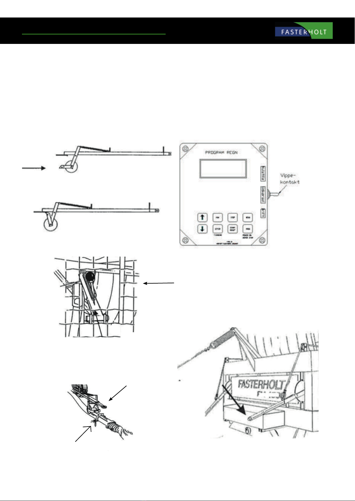
During irrigation
Safety stop
Stop pawl
Secure the hose chains with the long ground spikes. Lower the drawbar
over the hose and release the safety stop so the hose reel runs on the
hose.
During transport
Unwind the machine with the brake applied suciently to keep the hose
tight on the drum at all times with the electric brake.
If you do not lay the hose straight out, be very careful to ensure that the
hose is always tightened on the hose drum.
The machine should be unwound completely at least every 3rd time.
Before starting to unwind the machine, reset the COMPUTER. To do this,
press the TOGGLE SWITCH located on the side of the electric box upwards
(reset).
When unwinding the machine, the TOGGLE SWITCH must be in the centre
(unwind) so it cannot reset on the way out. After unwinding, press the
TOGGLE SWITCH down (operation).
Winding speed: Recommended max. 5 km/h
Preparing the machine for irrigation
ALWAYS REMEMBER that the TOGGLE SWITCH must be pressed down
during operation, otherwise the machine will not move.
Engage the pawl.
Tighten the V-belt (belt tension lever) so the spring is fully com-
pressed around the spacer pipe.
Operating instructions
Ground spike
8
Release the brake lever completely. Remember also to release the
electric brake (Remember that the electric brake connector must
be removed from the tractor).
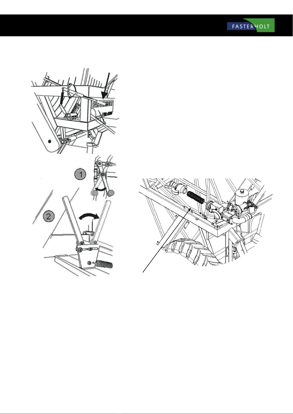
Before connecting the tractor to the rear of the machine, disen-
gage the gear and raise the drawbar at the front before starting
the machine.
Remember to close the decoupling valve (lever "1" must be
pulled out.)
REMEMBER to connect machines with coupling levers (lever "2"
pushed in).
Attach the charge hose to the hydrant. Then open the hydrant,
start the pump and irrigation can begin. The speed you want
to move at is set in Program Rain. You do not have to select a
gear as this is stepless speed regulation controlled by Program
Rain. On some other models, gears are selected according to the
machine instructions.
When starting irrigation, see the section that refers to the operat-
ing instructions for PROGRAM RAIN.
Preparing the machine after irrigation
After irrigation, tighten the brake and loosen the V-belt. Then open the bypass
valve (lever "1" must be pushed in) to get the gearbox out of gear (lever "2" pulled
out). If there is tension in the rear axle assembly, use a fork wrench to turn the
input shaft to release the coupling.
ALWAYS REMEMBER THAT THE COUPLING MUST BE RELEASED (COUPLING
LEVER PULLED BACK) WHEN THE MACHINE IS NOT MOVING BY ITSELF.
Maintenance
1x per week:
Check that no water is entering the oil on the rear axle assembly.
Lubricate the steering, roller chain for hose guides, roller chain for forward trac-
tion, cross track shaft for hose guide with water-repellent grease.
Check tyre pressure:
Rear wheels 2.9 bar/ 42.06 psi
Front wheels 2.9 bar/ 42.06 psi
Check that front and rear drawbars line up. If not, turn the lever on the side of the
machine by the front control cylinder. This is how to adjust the drawbars so they
line up. Turn the lever back again.
Clean the lter at the turbine outlet if required.
Check that the hose is positioned neatly.
Remember to check the guide pins in the hose guides regularly.
Remember to tighten the wheel bolts regularly.
NOTE:
The battery should be charged once a month during the season to maintain full
power and extend its useful life.
Preparation for winter
Drain water from the machine:
The machine is easily emptied with air (only done with special compressors).
Contact Fasterholt Maskinfabrik A/S if necessary.

9
REMEMBER !! Before unwinding the hose:
Open the lter coupling.
Open the valve in the base of the turbine.
On machines with high pressure stops, press START to open the main
valve and allow the water to ow out freely. (Disconnect battery lead
so stop valve does not close again.)
Remove the battery and do not install it until the next time you
use the machine.
Lubrication of:
Front wheel hubs, front spindle, hose guides, bearings on hose guides,
wheels.
Check for water in the oil in the rear axle assembly and hydraulic tank.
Oil in the rear axle assembly/gears should be changed every 1,000
hours. Hydraulic oil and lter should also be replaced every two years.
Lubricate the steering, roller chain for hose guides, roller chain for
forward traction, cross track shaft for hose guide with water-repellent
grease.
Check tyre pressure.
(see page 9)
Guide pins should be replaced every year.
Faults on the Irrigator
Check the following before calling a technician:
1. If the machine is irrigating, but not moving.
a. Check that machine is in gear.
b. Check if it is performing pre-irrigation or post-irrigation. (can be seen
on the display under menu 3.)
c. Check if pressure drop valve is closed.
d. Check that end stop sensor is in place. (can be seen on the display
under menu 3.)
e. Check that toggle switch is in operation position.
f. Check that decoupling valve is closed (for hydraulic motor).
g. Check that lter at turbine outlet is not blocked.
h. Check that turbine can turn easily.
2. If the machine does not wind up the hose properly, it may be that:
a. The hose guide needs to be adjusted:
To adjust the guide, remove the chain from the hose guide to the
cross track shaft. Then turn the cross track shaft until the hose guide
ts the hose again.
b. The guide pin is worn and needs to be replaced.
c. The V-belts are too slack or excessively worn: To tighten the belt,
move the hole plate at the end of the cable. If it cannot be moved any
further, the cable needs to be shortened.
3. Forced steering is not lined up and seems springy.
a. There is a leak at the coupling or assemblies, so the oil has drained out,
leaving air in the system.
b. The system must be vented (call a technician).
Setting the gun
The operating pressure of the gun should be 4.5 - 5.0 bar depending on the
type of gun and the water volume. For high water volumes, the pressure
should be higher.
The best spreading width is achieved at a sector angle of approx. 200 de-
grees. This means that the gun operates over an angle of 200 degrees.

10
Technical data
8. Data for FM 4400
Hose PEMD 100 mm:
Capacity up to 55 m - hose length from 200 to 550 m.
Hose PEMD 110 mm:
Capacity up to 75 m - hose length from 200 to 450 m.
Wheel size:
Rear wheels: 12.4"x36" x 10 ply - air pressure 34.8 psi / 2.4 bar
Front wheels: 11.5"/80x15.3" x 10 ply - air pressure 34.8 psi / 2.4 bar
Speed at 35 m and above:
15-30 metres per hour
Weight of FM 4400
Weight with water with 550 m/100 mm hose: 6948 kg.
Weight without water with 550 m/100 mm hose: 3813 kg.
Track width (Standard): 1600 mm.
Gun: Nelson SR 150
Oil in rear axle assembly......: 16 litres 80/90 gear oil
Track width 1600 mm.
Oil in at gear...: 1.5 litres 80/90 gear oil
Hydraulic oil......: 10 litres STATOIL Hvxa 46
Grease for lubrication: FUCHS Greaseway CAH 92 or equivalent.
Width 195 cm.
Length without drawbar 620 cm.
Height 363 cm.
11
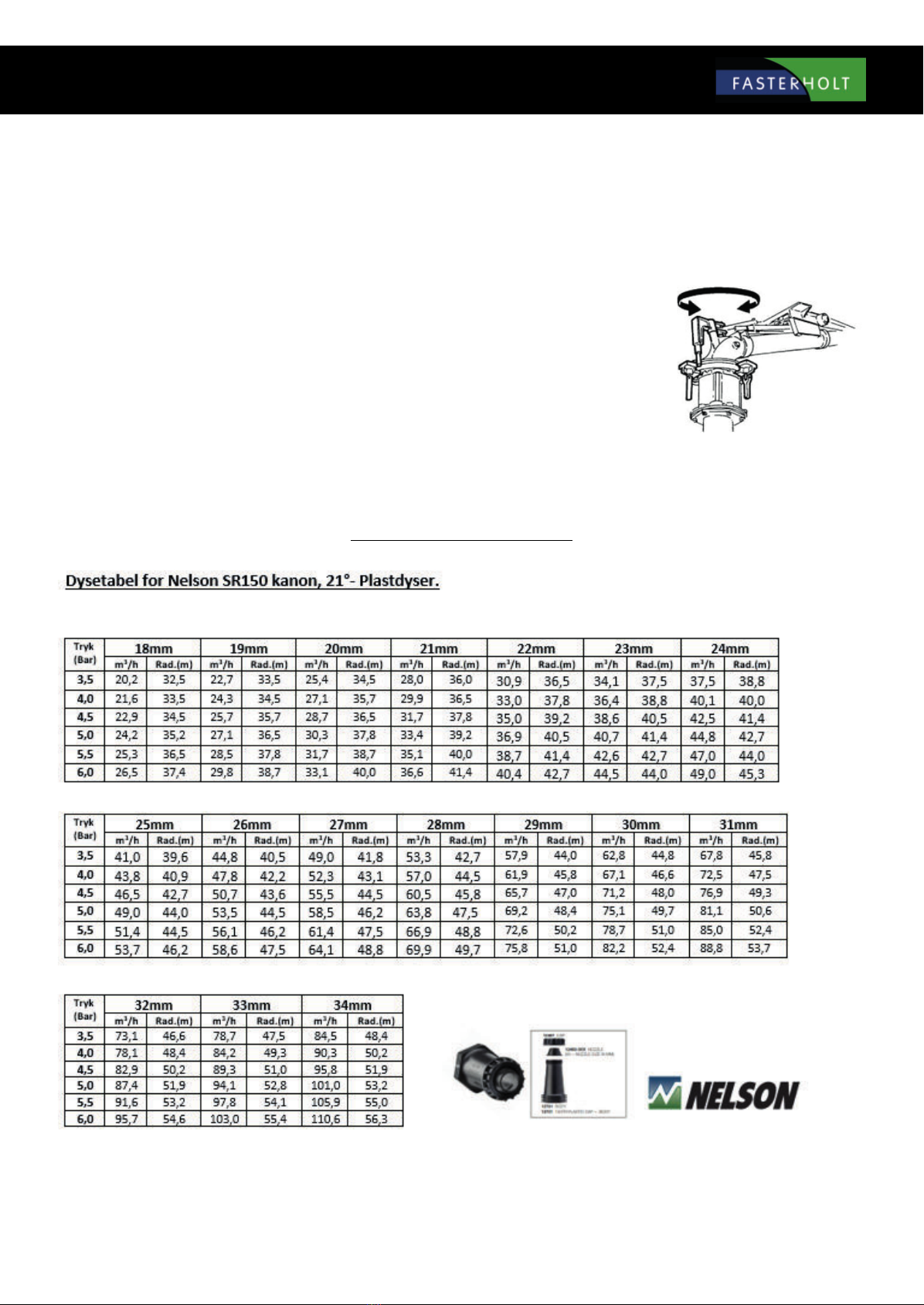
Nelson SR 150 is factory-adjusted to Danish conditions and ready to use after the following three steps:
1. Select and install the nozzle size that best suits your application. Performance data for the dierent sizes are shown in the table
below.
2. Adjust the stop on the part circle to obtain the desired irrigation angle.
3. There is a grease tting which should be checked once a week for relling.
ADJUSTMENT
The only thing you can adjust is the counterweight on the drive arm. By moving the
counterweight forward, the gun will slowly irrigate from side to side. If you move the
counterweight back, the gun will irrigate quickly. If it does not irrigate quickly enough, you
can remove the brake springs (no. 778474) in pairs (contact the service department).
WARNING: DO NOT ADJUST WHEN THE GUN IS IRRIGATING !!
DANGER........: HIGH WATER PRESSURE – STAY CLEAR !!
TABLE FOR NELSON SR 150

12

13
Functions:
Speed regulator
Pre- and Post-irrigation
4 dierent speeds on sections of the lane
Clock
Setting the start time
Stop time is shown on the display
Length of hose
Current speed
Battery volts
Charge regulator
Pressure sensor
Stop sensor
Speed sensor
Motor 1, regulating motor
Motor 2, stop motor
Slow start of turbine
Slow opening of inlet
Water volume + spreading width
Accessories:
GSM, SMS messages for remote control.
Analogue pressure sensor.
14
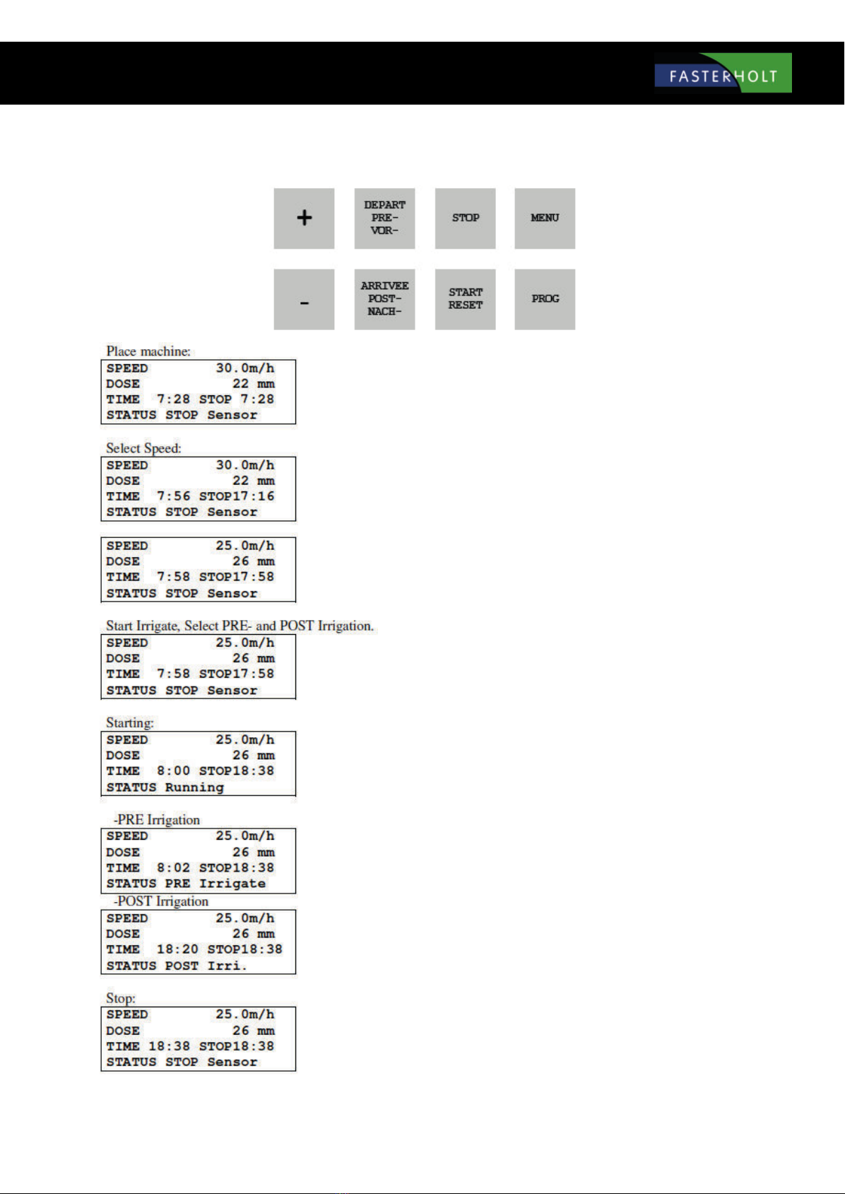
Short instructions for use
Move machine to a new lane. Display shows start and stop time. Pull hose out to
end of the lane. (e.g. 250 m)
Display now shows stop after 9h 20m. Press the "+" or "-" key to set the speed.
Speed can be adjusted during irrigation.
SPEED has decreased, DOSE has increased and STOP time is later.
Press START to start. Press PRE and POST for pre- and post-irrigation respectively.
STOP time will be later when PRE and POST irrigation are selected.
The turbine will start when the water pressure increases. After a short period,
the regulator nds the correct speed. Irrigation continues until STOP SENSOR is
activated at the end of the lane.
If pre-irrigation is selected, the turbine stops immediately after performing a start
and pre-irrigation. When the pre-irrigation time has elapsed, the turbine starts
and the machine changes status to Irrigating.
If post-irrigation is selected, the turbine stops at the end of the lane when the
stop sensor is activated. Post-irrigation then starts.
Stop sensor is activated, turbine and water are shut o. The machine is now ready
to be moved to a new lane.

15
Standard menu:
Standard display
SPEED
ZONE
DOSE
TIME
STOP
STATUS
DISTANCE
BATTERY
CHARGER ON
PRE
POST
Battery voltage.
MENU 2
Speed. Can be changed at any time during irrigation using the "+" and "-" keys.
Current zone 1...4, with corresponding speed. The speed cannot be changed. (Zone active)
The dose is calculated from the speed and constants and shows the current number of mm for irrigation. As SPEED
increases, DOSE decreases. (Constants 11 and 12)
To set the time: Set SPEED to 11.1 m/h and press the PROG key 3 + 1 times until the display shows <CONST 1 TIME>.
The time can then be set with the "+" and "-" keys. When the battery has been disconnected, the clock will show 0:00
until it is set again.
The time that irrigation is completed, incl. pre- and post-irrigation. If the clock is not set and shows 0:00, the total
irrigation time is displayed.
Irrigation status, e.g.:
<Stop Sensor >
<Irrigating >
<Pre-irrigating >
<Post-irrigating >
<LOW pressure >
See explanation in STATUS chapter.
If the display shows: LOW BATTERY instead of SPEED, the battery voltage is below 11.8 V and the battery needs to be charged.
Length of the unwound hose. The length can be changed immediately after pressing the PROG key 3 times, using the
"+" and "-" keys.
Shows when the battery is being charged by a solar cell. The battery is charged when the voltage is below 14.0 volts.
Shows the pre-irrigation time.
Shows the post-irrigation time.
The pre- and post-irrigation times can be changed immediately after pressing the PRE- or POST- keys, using the "+"
and "-" keys.
16
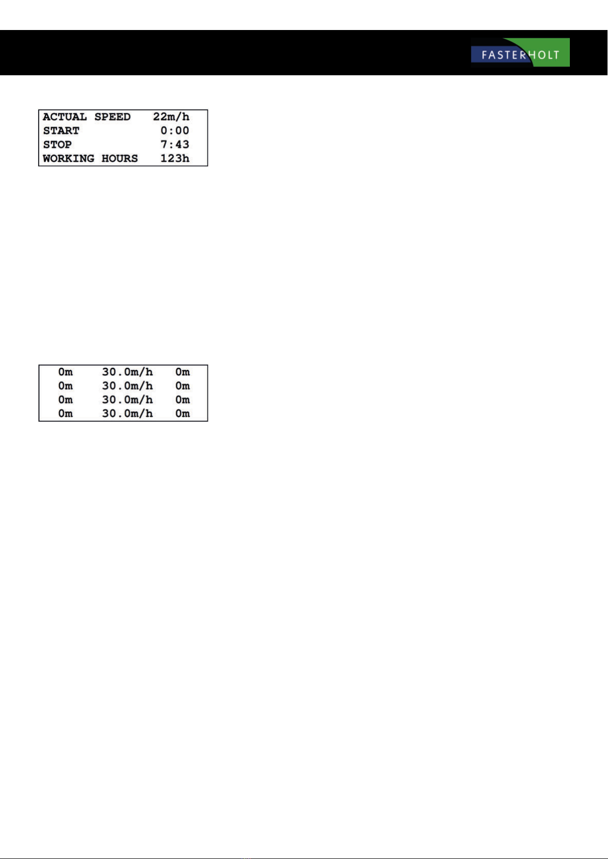
MENU 4
CURR. SPEED
START
STOP
OPERATING HOURS
Shows the current speed. That is, the speed at which the machine is moving now. This can be used to nd how fast
the machine can move. The current speed may dier slightly from the set speed, especially at the start. This does not
matter, as regulation ensures that the average speed within 10 metres is correct.
Start machine delay. The machine start time can be delayed by up to 24 hours. To set the start time, press the PROG
key 3 times, then set the time using the "+" and "-" keys.
The time that irrigation is completed with a delayed start.
Shows how many hours the machine has been running since the electronics started for the rst time.
MENU 5
This menu is for irrigation at dierent speeds in zones of the lane.
Press the PROG key 3 times to program the zones.
See later chapter for details.
17
PRE-IRRIGATION:
If pre-irrigation is required, press the PRE- key. The pre-irrigation time is calculated as 8 x the time to move 1 m at the current speed. The constant
can be changed individually for pre- and post-irrigation. (See constants). If pre-irrigation is selected, the machine will move forward approx. ½ m,
after which the machine will stop and stand still for as long as pre-irrigation is performed. Menu 2 shows the number of minutes remaining of the
pre-irrigation time. If you want to cancel pre-irrigation, press the START key. This will cancel both pre- and post-irrigation and the turbine will start.
POST-IRRIGATION:
If post-irrigation is required, press the POST- key. The post-irrigation time is calculated as 8 x the time to move 1 m at the current speed. The con-
stant "8" can be changed individually for pre- and post-irrigation. (See constants on page 16). Post-irrigation starts counting down when the magnet
is removed from the stop sensor. When the stop sensor is activated, the turbine stops and post-irrigation starts counting down (see menu 2). When
the post-irrigation time has elapsed, the main valve closes. (Opens in installations with negative pressure stops). For machines with mechanical end
stops: The turbine stops when the stop sensor is activated. When the post-irrigation time has elapsed, the turbine starts and the machine moves
to the mechanical end stop. Press START to cancel post-irrigation. If constant "8" (early stop) is selected, the machine will stop when it reaches the
selected distance.
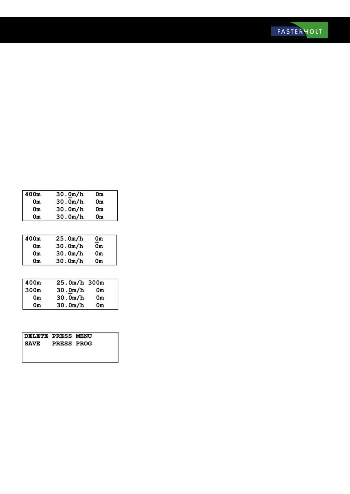
PROGRAMMING 4 DIFFERENT SPEEDS:
The hose must be unwound before programming, so the computer knows the number of metres in the irrigation lane. The following example
assumes that the unwound hose is 400 m. Press the PROG key 3 times and the display will show:
The desired speed can now be selected, in this case 25.0 m/h. Press the PROG key and the display will show:
The desired distance can now be selected, in this case 300 m. Press the PROG key and the display will show:
Now that the rst zone is programmed, apply the same procedure to all 4 zones. Zone 4 automatically ends at 0. When zone 4 is programmed, press
the PROG key again and the display will show:
If PROG is pressed, the program is stored and irrigation will be performed according to this program.
If MENU is pressed, the program is deleted and the speed is the same for the entire irrigation lane.

18
There are a variety of constants that can be modied by the user.
These constants will be stored for many years, even if the battery is removed.
Programming procedure:
Adjust the speed to 11.1 m/h to access the constants.
Press the PROG key 3 times in quick succession to access and change the constants.
Press the PROG key again to count forward to the constant you wish to change.
Press "+" and "-" to adjust the value of the constant.
Press the MENU key to save the change and the display will return to normal.
If the MENU key is not pressed, the display will return to normal after 1 minute and the change will not be saved.
CONSTANTS
Set Constant no. 0 to 111 to set the machine data.
Then press PROG to display the machine data.
Cons
no.
Note Fact.
Adj.
Min.
Value
Max.
Value
Description
0 100 - - Enter 111 to reach machine data
1 00:00 00:00 23:59 Time in line 2 is set
2 8 1 15 Pre irrigation
3 8 1 15 Pre irrigation
4 20 0 99 Supervision time [minutes]
5 1 1 15 1 English, 2 Danish, 3 German, 4 French, 5, Dutch
6 Swedish, 7 Spanish, 8 Italian, 9 Polish, 10 Japanese
11 Hungarian
6 0 0 2 0 = Stop for high pressure slow shutdown
1 = Stop for low pressure. valve opens and close again after 3 minutes
2 = Motor for stop disconnected
7 - 0 1000 Actual distance, can be set by the keyboard [m]
8 0 0 1000 Early stop [m]
( * Is only performed when Post Irrigation is selected * )
9 0 0 1000 Post irrigation before stop [m]
10 0 0 1000 Distance for alarm [m]
( * Disabled if Machine data 22. Sprinkler, is selected * )
11 40 5 120 Water ow [m3/h]
12 60 5 100 Spacing between irrigation lanes [m]
19
MACHINE DATA

20
Troubleshooting:
?
The turbine does not start when the START key is pressed.
Answer:
The magnet at the stop sensor is not in position or the sensor or sensor cable is damaged.
Stop sensor: The mark must be on when the magnet is in position and o when the magnet is removed. See Menu 3.
A damaged cable can be assembled in an epoxy moulded assembly or with shrinkable tubing and glue.
However, since the sensors are more sensitive than telephone cables in the ground, cable assembly must be seen as an emergency
solution.
If a pressostat is installed, the water must be pressurized. The mark must be on when there is pressure.
?
No numbers in the display.
Answer:
Battery disconnected. Fuse inside the box may have blown. The fuse will blow if the battery is wrongly connected.
An additional fuse is available from the factory on a single fuse terminal on the circuit board.
Fuse 5A. Battery voltage 12V. See Menu 2.
?
Clock is set to 00:00
Answer:
If the power is interrupted, the clock is reset. The end time is then the number of hours and minutes until irrigation is complete.
See page 15 for setting the clock.
?
The number of metres is not counted correctly and the speed is not correct.
Answer:
If the speed is measured with a roller running on the hose, check whether the roller is running smoothly or if it is not installed prop-
erly on the hose. You will also need to check that the roller sensor with cable is functioning properly. See Menu 3 Speed sensor.
The 2 marks must light up in the following order from the right during unwinding: The rst one turns on, then the second one
turns on, the rst one turns o, then the second one turns o. During rewind, this happens in reverse order.
?
Only half or perhaps 2/3 of the actual length has been counted.
Answer:
The stop bracket with magnet for the stop sensor may have jumped, so the magnet has been removed temporarily from the stop
sensor. This will reset the counter. Or a hose turn has been so loose that it has impacted the miswinding bracket.
This is usually the same as the impact on the stop bracket and has the same result.
Even if the metres are not saved in the memory, irrigation will still continue at the selected speed and the machine will stop as
normal. However, there will be deviations if the speed is measured on a gear disc and the calculation is based on formulas entered
in MACHINE DATA. This is because the electronics do not know which hose layer the machine is running on. Finally, the metres can
be entered manually.
See page 21. CONSTANT no. 7
Other manuals for FM4400
1
Table of contents
Other FASTERHOLT Farm Equipment manuals


Popular Farm Equipment manuals by other brands


Frontier
Frontier WR3008 Operator's manual

360 Yield
360 Yield 360 Y-DROP HAGIE STS 80 instruction manual

CSS
CSS MLGFM2000-2400 Assembling Instruction & Part List

Ag Leader Technology
Ag Leader Technology CaseIH 2055 manual

Simba
Simba Flatliner 500 Operator's manual & parts list

KUHN
KUHN GMD16 Operator's manual