FASTERHOLT FM2500 Installer manual

Irrigator
FM2500
Telephone: +45 97 18 80 66
Telefax: +45 97 18 80 40
E-mail: [email protected]
Web: www.fasterholt.dk
(EN) 21-03-2022
User Manual &
Spare Parts Catalogue
Fasterholt Maskinfabrik A/S
Ejstrupvej 22
7330 Brande
Denmark

2
Contents
EU Declaration of Conformity 3
General Safety 4
FM2500 Safety instructions/warnings 4
Product labelling 6
Symbols used in this product 6
Operating instructions 7
Starting your irrigator 7
Preparing the machine for irrigation 8
Preparing the machine after irrigation 9
Maintenance 10
Preparation for winter 10
Faults on the irrigator 11
Technical data 12
Nelson SR 150 12
Spare parts 32

3
EEC Declaration of conformity
Fasterholt Maskinfabrik A/S
CVR:
58 83 28 12
TEL:
+45 97 18 80 66
FAX:
+45 97 18 80 40
E‑Mail:
mail@fasterholt.dk
Manufacture (name and
address):
Adresse: Ejstrupvej 22,
Fasterholt
Ort: 7330 Brande
Country: Denmark
Web: www.fasterholt.dk
Hereby is certified that the following
product:
Description, ID/mark, type:
Serial No. if any:
Notified body if any:
EEC-type certificate if any:
Harmonised standards if any:
EN 908:1999+A1:2009.
DS/EN/ISO 12100:2011.
DS/EN/ISO 14120:2015.
Is made according to the announcement no.693 of 10. Jun 2013 that implements the
DIRECTIV 2006/42/EC.
Name, title and signature of manufacture:
Date Signature
Irrigator FM 2500
EU Declaration of Conformity

4
General Safety
!!! Important!!!
Read this manual carefully before using your irrigator!
Your new Fasterholt irrigator is a high quality, Danish built machine, but even
the best machines only deliver top results when they are properly handled
and maintained.
To ensure that the machine complies with the EU Machinery Directive, only
original spare parts may be used. Otherwise, compliance will be lost and
safety will be entirely at your own risk.
FM2500
Fasterholt FM2500 is a self-propelled irrigator that drives across the eld and
unwinds the hose by itself. A turbine is used to power the machine and hose
winding and irrigation stop automatically when the machine gets back to the
hydrant and the xed stop.
The machine is available with an underpressure stop or an overpressure
stop. With the overpressure stop function, make sure that the pump is either
switched o via a pressostat or can dispose of water by other means when
the machine stops irrigation. With the underpressure stop function, the pump
must be stopped via a pressostat.
The machine must be supplied with a maximum pump pressure of 12 bar. The
recommended pressure 7-9 bar.
The irrigator is only suitable for irrigation with clean water from a drilled well
or a watercourse.
We must point out that any damage caused by incorrect operation and/or
negligence is not covered by the warranty. Fasterholt Maskinfabrik A/S only
guarantees new machines sold through an authorised Fasterholt dealer. Any
modications made to the design of the irrigator shall exclude Fasterholt
Maskinfabrik A/S of any liability and shall void the warranty.
Safety instructions/warnings
As this machine is used for eld irrigation involving high water pressure,
there is a risk of injury if the machine is used inappropriately. The warnings
and safety instructions given here must therefore be respected and followed
precisely.
• It is forbidden to stand on the machine during irrigation, as this may
result in fatal injury.
• Only one person (operator) should be in the vicinity of the machine
during transport, setup and dismantling.
• When starting the machine on falling ground, you must be VERY careful
not to disconnect the tractor from the machine until the irrigator has
been put into gear, otherwise the machine may run away.
• All shields are tted for your protection. Please leave them in place.
• Remember to tighten all wheel bolts.
• If a wheel is removed, the machine must be jacked up and very stable,
because it will fall completely on its side if it overturns. This may result in
fatal injury.
WARNING!
• To perform an EMERGENCY STOP, pull the cable for the miswinding bar,
pull the miswinding bar or press STOP on the Program Rain computer.
• V-belts may only be tted after the machine has been unwound for the
rst time. (Only the rst time the machine is used for irrigation).
• The gun must face out to the side when unwinding the machine.
• Stand aside when the gun is operating.
• Warning against contact with overhead power lines with the machine or
water jet. Therefore avoid irrigation on or near power lines.
• During transport on uneven roads/elds, move VERY carefully according
to the conditions.
• When parking the machine, use the wheel chocks mounted by the rear
wheels.
• DANGER! Avoid welding in the paint layer! Before welding, remove all
paint from the welding area – avoid inhalation of grinding dust.
• Hydraulic oil can be harmful to health: - Skin contact may cause allergies
- Inhalation of oil mist may cause lung disease - Leakage of oil under
high pressure is dangerous, an oil jet can enter the skin, eyes, etc.

5
• If a hydraulic system leak is found, stop the system immediately and
rectify the fault.
• Note that due to operation, the oil may be 70 degrees Celsius or even
hotter. This can lead to a risk of scalding during separation of the
hydraulic system.
• IMPORTANT: Maximum battery charging power is 2 amps. Charging
more than 2 amps may cause the battery to crack. The battery must be
charged at a temperature between 0 °C and +40 °C. Never place the
battery in a sealed container while charging. During winter, the battery
must be removed and stored in a dry place indoors in a fully charged
state.
• Avoid sparks and ames on and around the battery.
• Do not short circuit the battery.
• Never disassemble the battery.
• If you come into contact with the battery's sulphuric acid, wash
immediately with water. If acid comes into contact with eyes, rinse
thoroughly with water and seek medical attention immediately.
• Pay attention to the battery compartment. If there are cracks,
deformities, electrolyte leakage, etc., replace the battery immediately.
• If the battery is dirty, clean it immediately.
• Disposal of oil spills: - If oil spills are found, they should be cleaned up
immediately with rags or oil absorbent powder. - Spilled products, as
well as rags and powder used for oil spills, must be stored in sealed metal
containers and delivered to the municipal collection site.
• Hoses, tyres and other parts of the irrigation machine must be disposed
of at an approved recycling site.
If the machine is to be moved via public roads, it must rst be drained of
water.

6
Product labelling
Symbols used in this product
The following symbols are used in this product and the following documentation.
WARNING Indicates a potentially dangerous situation which, if not prevented, could result in death or serious
injury.
LUBRICATION Indicates lubrication is required as per the service description.
SERVICE WARNING Indicates a service hazard
SMØRING
Str: 100x45 mm
HUSK efterspænding
af hjulbolte
Str: 69x20 mm

7
Operating instructions
Starting your irrigator
Move the machine to the eld in the transport position. When the machine is at the crop to be irrigated, disconnect the tractor and position the front drawbar
vertically.
REMEMBER!
When starting the machine on falling ground, you must be VERY careful not to disconnect the tractor from the machine until the irrigator has been
put into gear, otherwise it may run away.
Connect the tractor to the rear drawbar. The machine then winds up in the crop and stops. Disengage the pawl
Tap the ground spikes into the xed stop bar. Lower the drawbar over the hose , and release the safety stop so the hose reel runs on the hose. Unwind the
machine with the brake applied suciently to keep the hose tight on the drum at ALL times.
Pal.
8
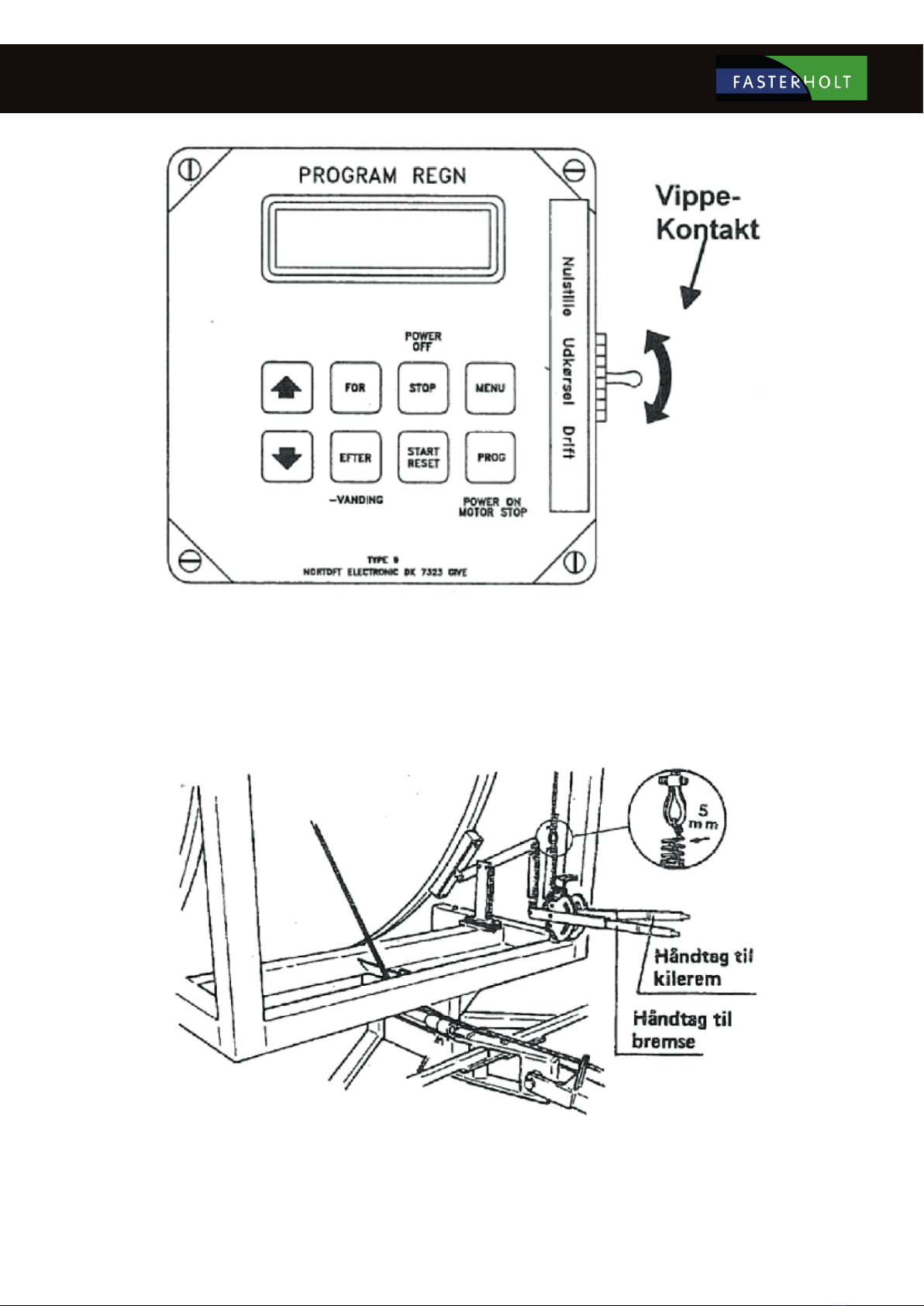
When unwinding the machine, the toggle switch must be set to the centre position (unwind) so it cannot reset on the way out.
Preparing the machine for irrigation
ALWAYS remember that the toggle switch must be pressed down during operation, otherwise the machine will not move. Engage the pawl.
Tighten the V-belt so there is at least 5 mm air in the spring. Release the brake lever completely. Also remember that the electric brake must be released.
9
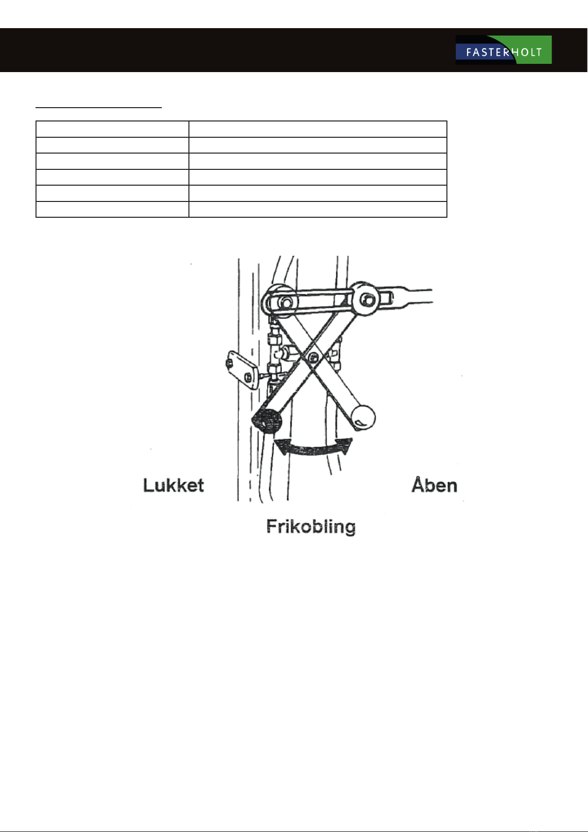
Put the machine in gear. Remember to select the right gear for the speed you want to drive at. Refer to table below or in the machine’s electrical cabinet.
Table of forward speeds for FM2500
1. Gear 5-12 metres per hour
2. Gear 8-18 metres per hour
3. Gear 15-33 metres per hour
4. Gear 22-48 metres per hour
5. Gear 33-73 metres per hour
6. Gear 70-130 metres per hour
Remember that the decoupling valve must be closed. (Lever must be pulled out).
Attach the charge hose to the hydrant. Then open the hydrant, start the pump and irrigation can begin. Place the chock on the hose where you want to stop
irrigation. When starting irrigation, see the section that refers to the operating instructions for Program Rain.
Preparing the machine after irrigation
After irrigation, tighten the brake and loosen the V-belt. Then open the bypass valve (lever must be pushed in) to get the gearbox out of gear. If there is
tension in the rear axle assembly, use a lever to turn the input shaft to get it into neutral.
ALWAYS REMEMBER THAT THE GEARBOX MUST BE IN NEUTRAL WHEN THE MACHINE IS NOT MOVING BY ITSELF.
10
Maintenance
Once a week in the irrigation season:
Check that no water is entering the oil on the rear axle assembly. Lubricate the steering, roller chain for hose guides, roller chain for forward traction, cross
track shaft for hose guide with water-repellent grease.
Check tyre pressure (35 psi)
Clean the lter at the turbine outlet if required
Check that the hose is positioned neatly.
Remember to check the guide pins in the hose guides regularly.
Remember to tighten the wheel bolts regularly.
Note: The battery should be charged once a month during the season to maintain full power and extend its useful life.
Preparation for winter
Drain water from the machine:
Unwind the hose completely, release the brake and tighten the V-belt, but do NOT put the machine in gear. Then drive the machine into the tractor.
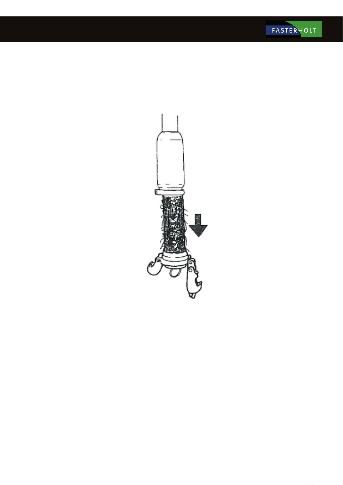
REMEMBER before unwinding the hose:
Open the lter coupling. Open the valve in the base of the turbine. On machines with overpressure stops, press START on the computer to open the main
valve and allow the water to ow out freely.

11
Remove the battery and do not install it until you use the machine again.
Lubrication and oil:
Lubricate front wheel hubs, front spindles, hose guides, bearings on hose guides and drums. Check for water in the oil in the rear axle assembly and hydraulic
tank. Oil in the rear axle assembly should be changed every two years. Hydraulic oil and lter should also be replaced every two years.
Faults on the irrigator
Check the following before calling a technician:
1. If the machine is irrigating, but not moving:
a. Check that machine is in gear.
b. Check if it is performing pre-irrigation or post-irrigation.
(Can be seen on the display when the LED is on).
c. Check if pressure drop valve is closed.
d. Check that end stop sensor is in place.
(Can be seen on the display when the LED is on)
e. Check that toggle switch is in operation position.
f. Check that decoupling valve is closed (for hydraulic motor).
g. Check that lter on turbine is not blocked.
h. Check that turbine can turn easily.
i. Check that the brake is released.
j. Check that the hose is wound up tightly. If it is loose, tighten it. This is done by manually rotating the drum.
Remember that the pawl must be locked securely.
2. If the machine does not wind up the hose properly, it may be that:
a. The hose guide needs to be adjusted.
To adjust the guide, remove the chain from the hose guide to the cross track shaft. Then turn the cross track shaft
until the hose guide ts the hose again. Fit the chain again.
b. The guide pin is worn and needs to be replaced.
c. The V-belts are too slack or worn. To tighten the belt, move the hole plate at the end of the cable. If it cannot be
moved any further, the cable needs to be shortened.

12
Nelson SR 150 is factory-adjusted to Danish conditions and ready to use after the following three steps:
1. Select and install the nozzle size that best suits your application. Performance data for the dierent sizes are shown in the table
below.
2. Adjust the stop on the part circle to obtain the desired irrigation angle.
3. There is a grease nipples which should be checked once a week for relling.
ADJUSTMENT
The only thing you can adjust is the counterweight on the drive arm. By moving the counterweight forward, the gun
will slowly irrigate from side to side. If you move the counterweight back, the gun will irrigate quickly. If it does not
irrigate quickly enough, you can remove the brake springs (no. 778474) in pairs (contact the service department).
WARNING: DO NOT ADJUST WHEN THE GUN IS IRRIGATING!!
DANGER........: HIGH WATER PRESSURE – STAY CLEAR!!
TABLE FOR NELSON SR 150
Technical data

13
Hose PEL 100mm:
Capacity up to 55m3, hose length from 200 to 500m
Hose PEL 110mm:
Capacity up to 75m3, hose length from 200 to 375m
Speed at 30m3 and above: 15–130 metres per hour
Weight:
Without water with 325m Ø110mm hose: 2,945 kg
With water with 325m Ø110mm hose: 4,925 kg
Gun:
Nelson SR150
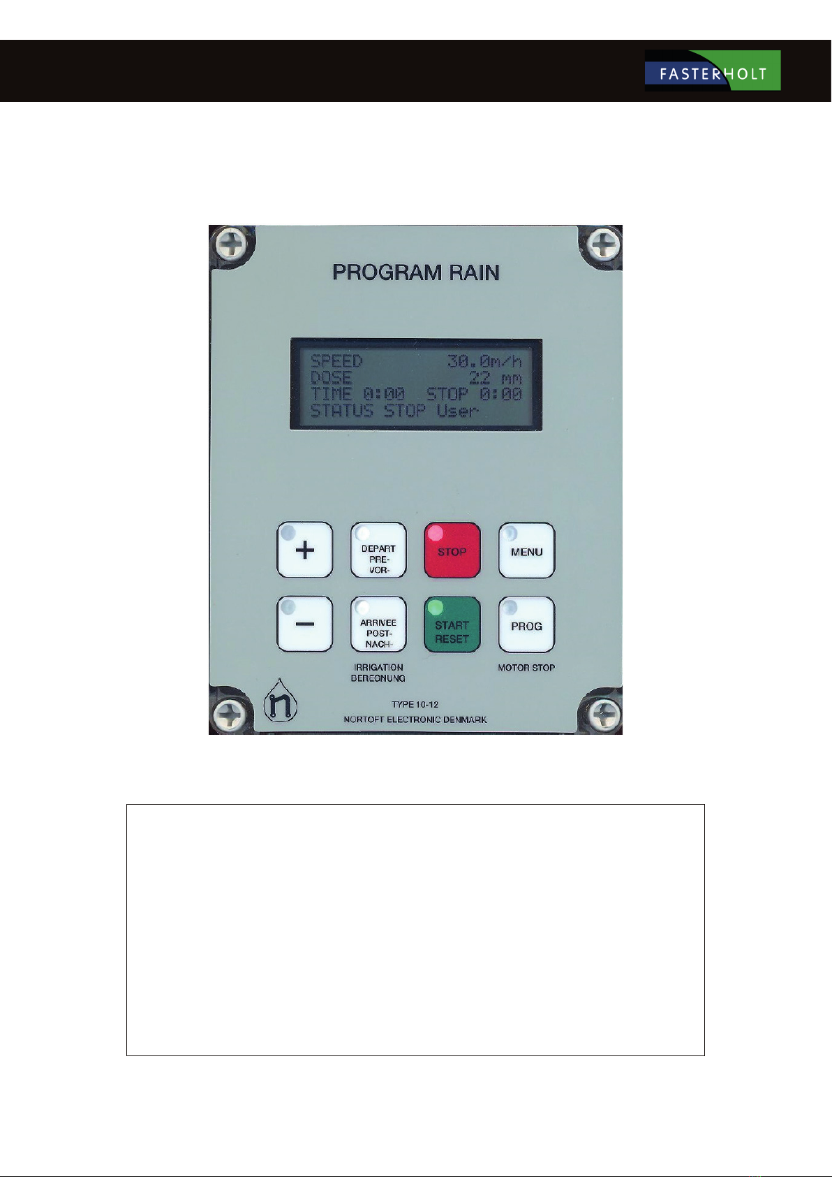
Computer:
Nørtoft Electronic, Program Rain 10-12
Tyres:
Front wheels (air pressure: 35psi) 900" x 16" x 6 ply 3rib
Rear wheels (air pressure: 35 psi) 10 x 28" x 8 ply
Oil and grease:
Oil in rear axle assembly: 33 litres Statoil 80/90 gear oil
Hydraulic oil: 10 litres Statoil Hydraway HVXA 46
Grease for lubrication: Statoil Moly Way EP2 or equivalent.
Track width: 1
62cm (standard)
Options: 152cm, 172cm, 182cm, 192cm
Length: 5,200mm
Width: 1,800mm
Height: 3,600mm
14
Functions:
Speed regulator
Pre- and Post-irrigation
4 dierent speeds on sections of the lane
Clock
Setting the start time
Stop time is shown on the display
Length of hose
Current speed
Battery volts
Charge regulator
Pressure sensor
Stop sensor
Speed sensor
Motor 1, regulating motor
Motor 2, stop motor
Slow start of turbine
Slow closing of inlet
Water volume + spreading width
Accessories:
GSM, SMS messages for remote control.
Analogue pressure sensor.

15
Short instructions for use
Move machine to a new lane. Display shows start and stop time. Pull hose
out to end of the lane. (e.g. 250 m)
Display now shows stop after 9h 20m. Press the "+" or "-" key to set the
speed. Speed can be adjusted during irrigation.
SPEED has decreased, DOSE has increased and STOP time is later.
Press START to start. Press PRE and POST for pre- and post-irrigation
respectively. STOP time will be later when PRE and POST irrigation are
selected.
The turbine will start when the water pressure increases. After a short period,
the regulator nds the correct speed. Irrigation continues until STOP SENSOR
is activated at the end of the lane.
If pre-irrigation is selected, the turbine stops immediately after performing
a start and pre-irrigation. When the pre-irrigation time has elapsed, the
turbine starts and the machine changes status to Irrigating.
If post-irrigation is selected, the turbine stops at the end of the lane when
the stop sensor is activated. Post-irrigation then starts.
Stop sensor is activated, turbine and water are shut o. The machine is now
ready to be moved to a new lane.
16
General instructions for use
Standard display
Standard display, ZONE irrigation is selected.
Press the MENU key 1 time to display menu 2
Press the MENU key 2 times to display menu 3
Press the MENU key 3 times to display menu 4
Press the MENU key 4 times to display menu 5
Press the MENU key 5 times to display menu 6
(Only if GSM is selected)
When appears in the display, this indicates that the relevant function is ON.
17
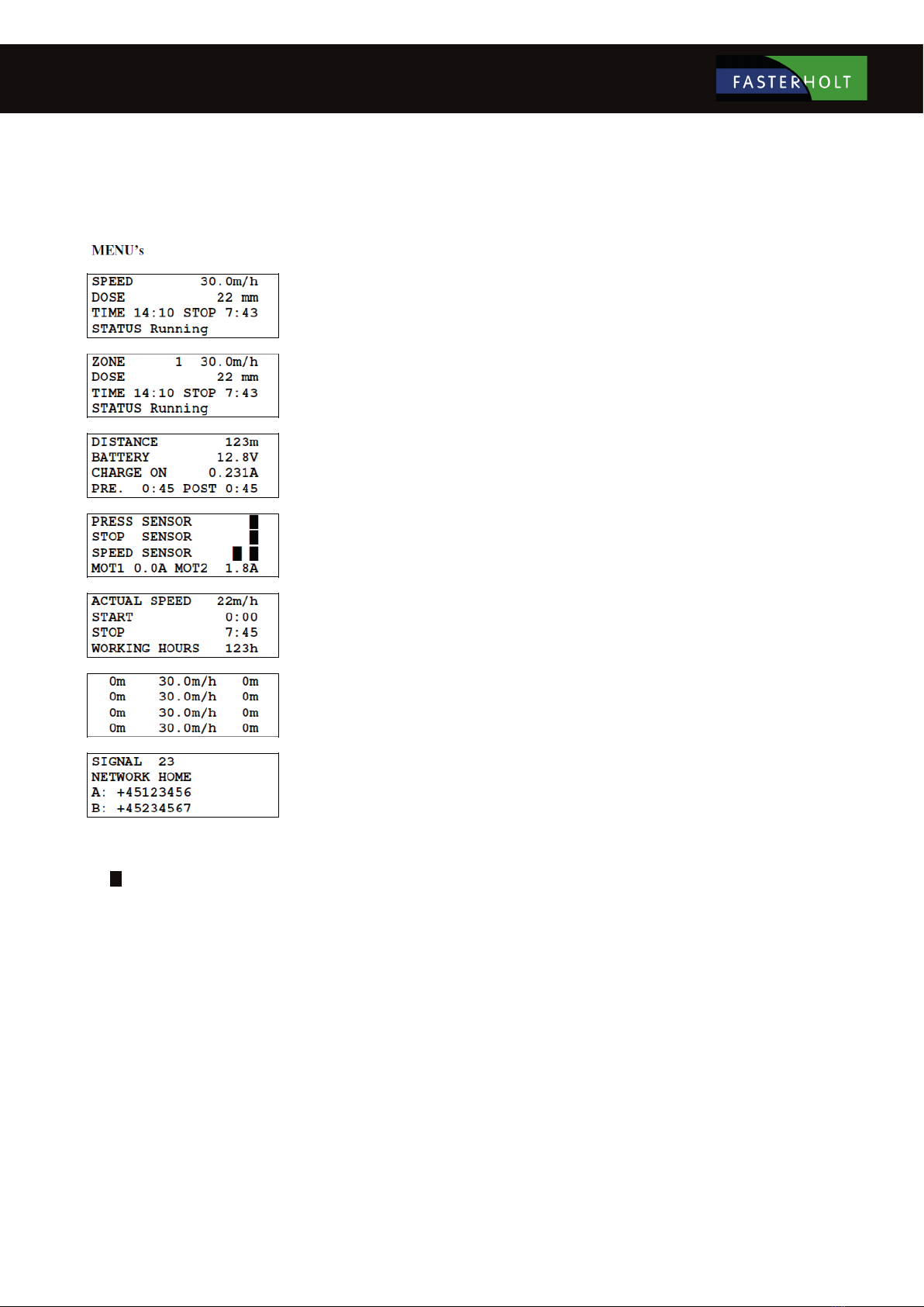
Standard menu:
Standard display
SPEED
ZONE
DOSE
TIME
STOP
STATUS
Speed. Can be changed at any time during irrigation using the "+" and "-" keys.
Current zone 1...4, with corresponding speed. The speed cannot be changed. (Zone active)
The dose is calculated from the speed and constants and shows the current number of mm for irrigation. As
SPEED increases, DOSE decreases. (Constants 11 and 12)
To set the time: Set SPEED to 11.1 m/h and press the PROG key 3 + 1 times until the display shows <CONST 1 TIME>.
The time can then be set with the "+" and "-" keys. When the battery has been disconnected, the clock will show 0:00 until it is
set again.
The time that irrigation is completed, incl. pre- and post-irrigation. If the clock is not set and shows 0:00, the
total irrigation time is displayed.
Irrigation status, e.g.:
<Stop sensor >
<Irrigating >
<Pre-irrigating >
<Post-irrigating >
<LOW pressure >
See explanation in STATUS chapter.
If the display shows: LOW BATTERY instead of SPEED, the battery voltage is below 11.8 V and the battery needs to be charged.
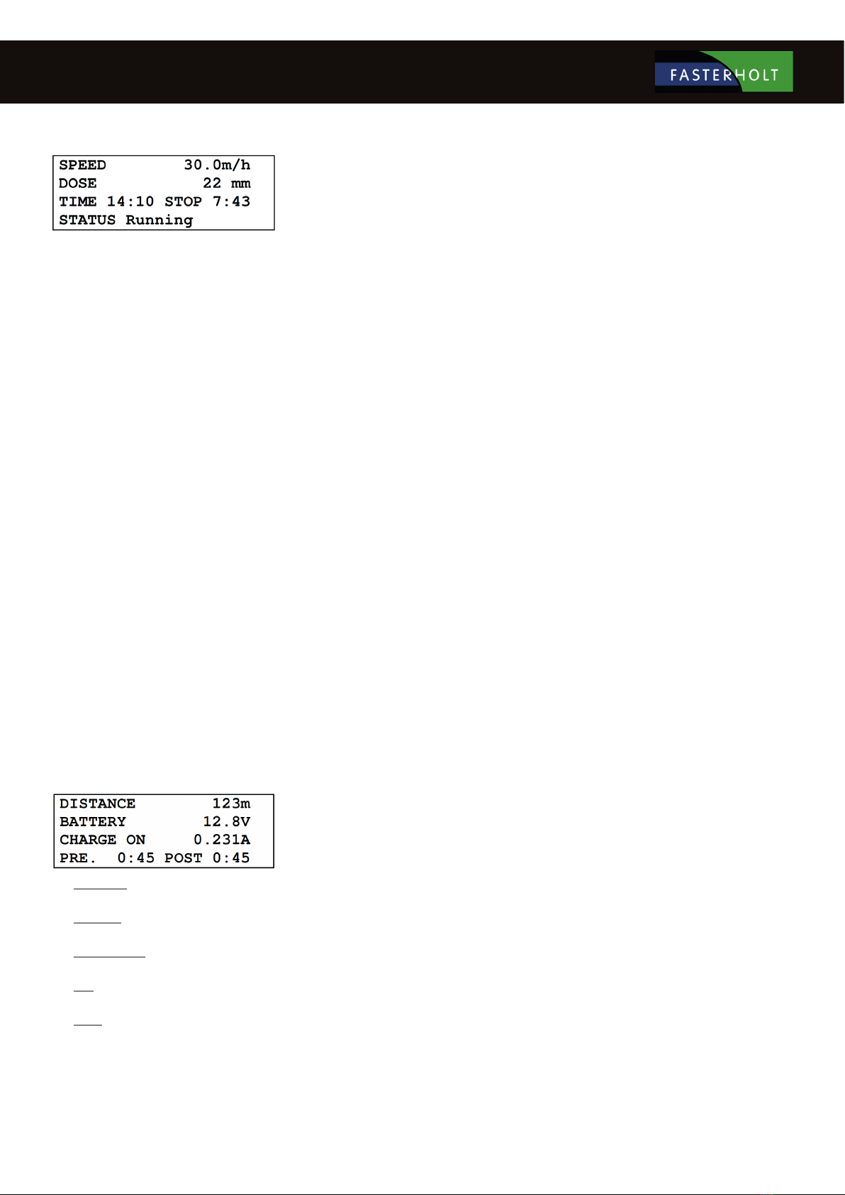
DISTANCE
BATTERY
CHARGER ON
PRE
POST
Length of the unwound hose. The length can be changed immediately after pressing the PROG key 3 times, using
the "+" and "-" keys.
Battery voltage.
Shows when the battery is being charged by a solar cell. The battery is charged when the voltage is below 14.0
volts.
Shows the pre-irrigation time.
Shows the post-irrigation time.
The pre- and post-irrigation times can be changed immediately after pressing the PRE- or POST- keys, using the
"+" and "-" keys.
MENU 2

18
MENU 3
PRESSURE SENSOR
Shows that the pressure is high when block is lit. The machine can only move when the pressure is high. If no pressure sensor is
tted (machine data 14 = 0), the machine will operate regardless of pressure status.
The machine can be tted with analogue pressure sensors. Sensors must be connected according to the diagram. Pressure sensor functions,
except for pressure display, are the same as for digital pressure sensors. There are constants for the pressure sensor type. Similarly, set point
and hysteresis can be selected for each machine.
Shows pressure in [BAR] (00.0) or [PSI] (000). Pressure is high when is lit.
The machine can only move when the pressure is high.
If no pressure sensor is tted (machine data 14 = 0), the machine will operate regardless of pressure status.
STOP SENSOR
Shows that the magnet is aligned with the stop sensor when block is lit.
The machine can only start when the magnet is aligned with the stop sensor.
The stop sensor has 3 functions:
1. Reset distance.
2. Post-irrigation.
3. Stop pulses to the regulator motor.
SPEED SENSOR
For the speed sensor test, block is only lit when the magnet passes the sensor.
MOT1, MOT2
Displays the current motor current. When the current exceeds 4.5 A, the motor stops.
If the current exceeds 4.5 A and the valve is not in the outer position, there may be a blockage in the valve.
19
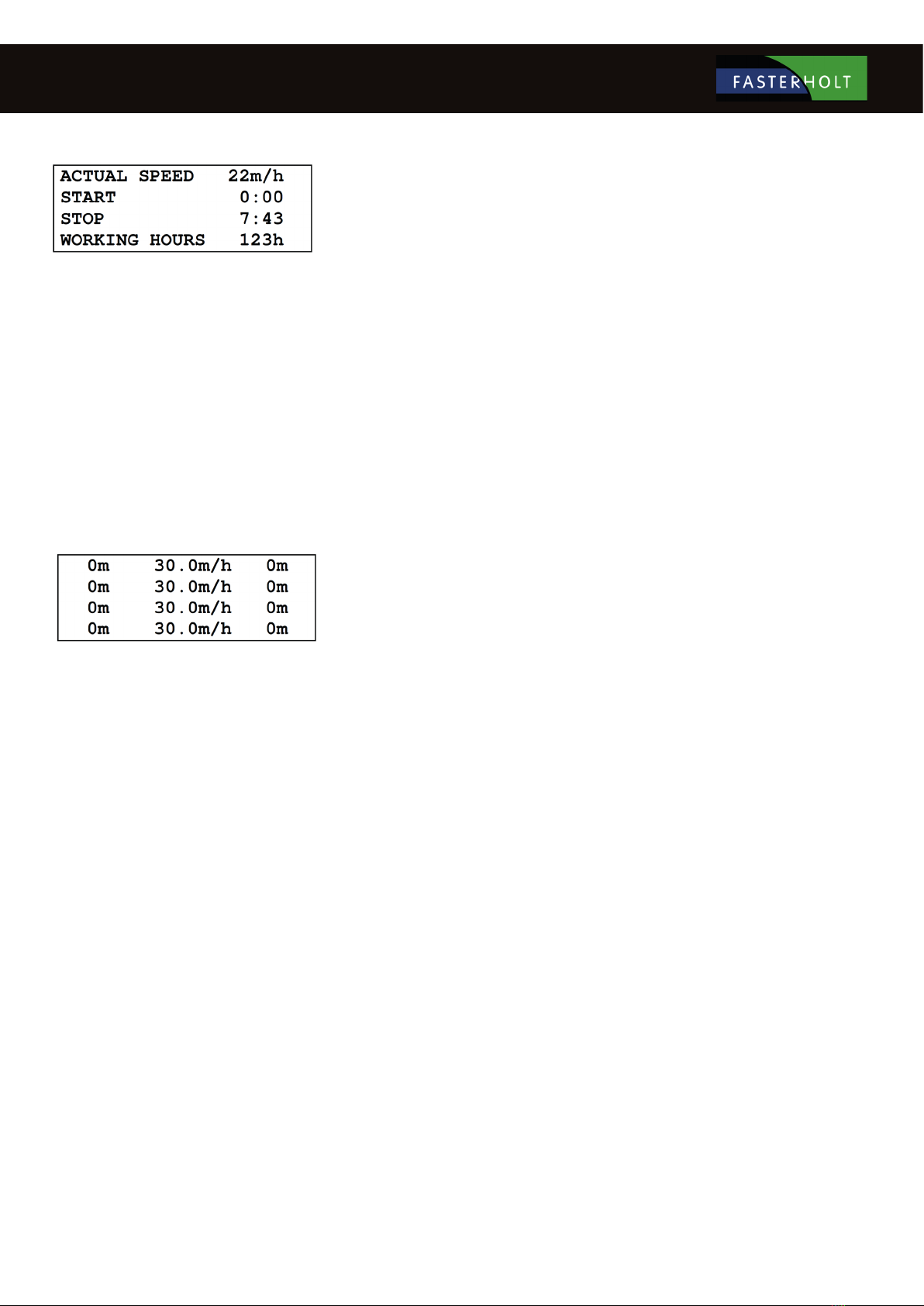
MENU 4
CURR. SPEED
START
STOP
OPERATING HOURS
Shows the current speed. That is, the speed at which the machine is moving now. This can be used to nd how
fast the machine can move. The current speed may dier slightly from the set speed, especially at the start. This
does not matter, as regulation ensures that the average speed within 10 metres is correct.
Start machine delay. The machine start time can be delayed by up to 24 hours. To set the start time, press the
PROG key 3 times, then set the time using the "+" and "-" keys.
The time that irrigation is completed with a delayed start.
Shows how many hours the machine has been running since the electronics started for the rst time.
MENU 5
This menu is for irrigation at dierent speeds in zones of the lane.
Press the PROG key 3 times to program the zones.
See later chapter for details.

20
MENU 6
SIGNAL GSM signal strength.
NETWORK GSM network.
A: First number on "SMS" list.
B: Second number on "SMS" list.
See GSM chapter for details.
START:
The turbine can only start if the magnet is aligned with the end stop sensor (or end stop sensors). See menu 3 for control of the STOP SENSOR. Press the
START key to turn on the water. The regulator valve for bypass around the turbine then closes. (Turbine starts). If the end stop sensor is not in place, only the
main valve can be opened, which then immediately closes again. Used to relieve pressure before removing charge hose from hydrant.
DEFERRAL OF START TIME
First press the STOP key to shut o the water supply. Then press the MENU key 3 times and PROG 3 times. The start time can be set using the "+" and "-" keys.
Finally, select pre- and post-irrigation. To exit, press MENU. Info: The clock can only be set forwards.
STOP:
When the magnet is removed from the end stop sensor, the turbine stops and the main valve shuts o the water (turns on the water at negative pressure). If
post-irrigation is selected, rewinding stops when the magnet is removed from the sensor. When the post-irrigation time has elapsed, the main valve closes.
When the STOP key is pressed, the turbine stops immediately and the main valve shuts o the water, regardless of whether post-irrigation is selected.
SUPERVISION:
Program Rain has a built-in supervision system. The supervision system will be activated if for any reason the machine has water in the same location for
longer than a specied time. This time is factory-set to 20 minutes. If the time is set to 0, there is no supervision. (See constants on page 17 for setting the
supervision time.) If speed supervision less than 50 % of pre-selection is required, select speed supervision together with the above time.
SPEED:
The speed is set using the "+" and "-" keys. First count up in steps of 0.1 m/h. After 10 steps, count up in steps of 1 m/h. The speed can be changed at any
time during irrigation. If the speed changes during irrigation, the dose and time for the remaining irrigation will be calculated immediately based on the new
speed.
Table of contents
Other FASTERHOLT Farm Equipment manuals


