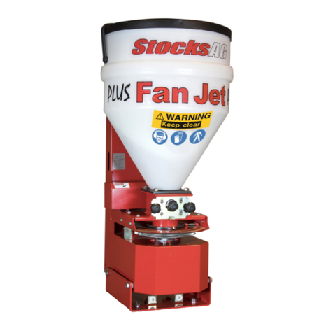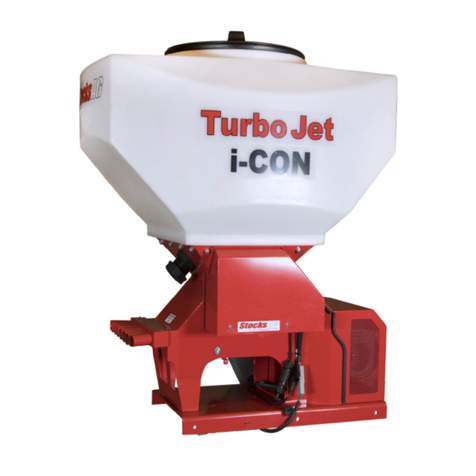
6
6 Safety
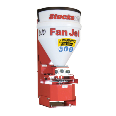
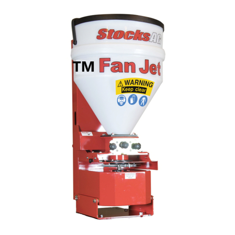
Ensure care is taken when lifting the machine
Safe lifting practice to be observed when handling as the net weight is over
25kg
We advise safety shoes and protective gloves are worn when handling the machine
Assistance will be required when lifting or lowering the machine
Care to be taken to avoid crushing due to the weight of the machine.
When lifting or fitting the machine to the parent vehicle or implement ensure work is performed on level ground
or flat surface to avoid slipping, stumbling or falling.
PERSONAL PROTECTION EQUIPMENT It is the responsibility of the operator or maintenance
engineer to ensure safe handling of the machine and the appropriate personal protection
equipment is worn for the material being applied and to prevent contamination to the machine or
the environment.
WARNING Always observe all application standards and guidelines provided by the product
manufacturer as some seed dressings and granular products may be toxic !
NOTE if unsure contact your seed or product supplier for more information.
If applying slug pellets or other toxic material and the parent vehicle has a closed cab the operator must
ensure the cabin is always closed and the air filter system is in good order.
If fitted to a UTV vehicle ensure the stability of the parent vehicle is not affected when the machine is in use.
If in doubt contact the vehicle manufacturer for more information.
After working the machine ensure that any unused product is returned safely to its original packaging
Stocks AG Ltd. does not accept any liability for the storage and use of the material being applied
If unsure contact the material supplier for more information.
WARNING Always adhere to the warning information and do not remove any guard whilst
the machine is in operation .
WARNING
Do not put your hands inside the hopper when the agitator
motor is turning as the agitator shaft inside the hopper rotates at high speed
and is sharp and dangerous.
The machine may only be used, maintained and repaired by persons who have relevant
experience or a machinery dealer who is aware of any risks involved.
The applicable accident prevention regulations as well as the other generally safety
related, occupational health and road traffic regulations must also be observed.
The manufacturer is not liable for any damage resulting from unauthorised modifications and the use of
components and auxiliary parts
The machine must be checked regularly by the operator (before each use) for any damage loose bolts or
electrical connections, vibrations, unusual sounds, and to ensure they function correctly.
The machine must not be operated in wet weather conditions or during thunderstorms.
Observe the generally applicable safety and accident prevention regulations
Always empty the hopper of toxic materials to prevent harm to humans and animals after each use and prior to
storage.
WARNING
Always isolate the power supply if servicing or leaving the machine unattended.
NOTE UK users; more information regarding slug pellet and best practice available at
www.getpelletwise.co.uk


