Honeywell ML8824 Series Operator's manual
Other Honeywell Controllers manuals

Honeywell
Honeywell Aquastat L4006 User manual

Honeywell
Honeywell WV8860C User manual
Honeywell
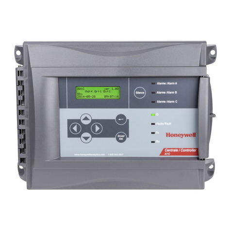
Honeywell 301C User manual
Honeywell
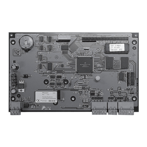
Honeywell PRO22IC User manual
Honeywell
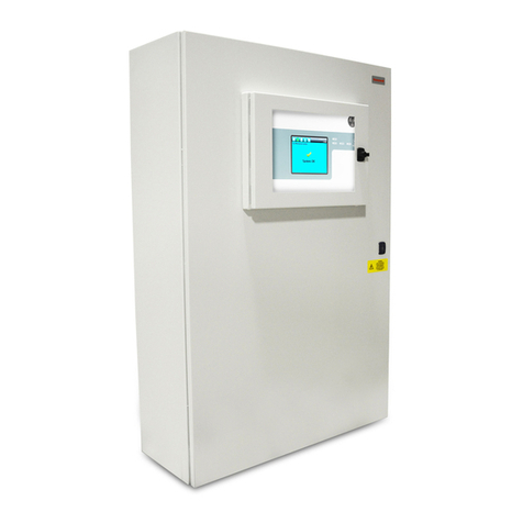
Honeywell touchpoint Pro User manual
Honeywell
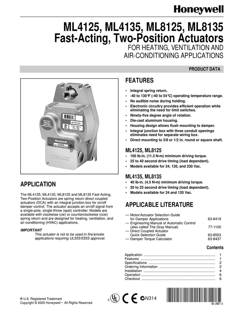
Honeywell ML4125 Operation manual
Honeywell
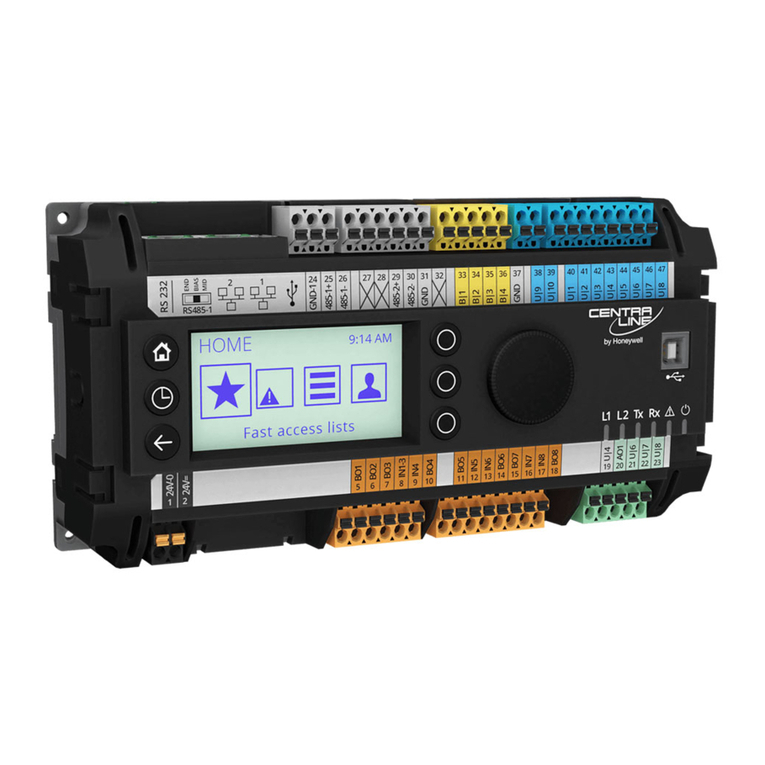
Honeywell CENTRA LINE EAGLEHAWK Installation and operation manual

Honeywell
Honeywell TRADELINE VR4304 User manual
Honeywell
Honeywell S4965V3250 Operating and installation instructions
Honeywell
Honeywell Experion C300 User manual

Honeywell
Honeywell N20 Series User manual
Honeywell
Honeywell MS7503A2023 User manual
Honeywell
Honeywell Ex-Or MLS2000DALIHBW Installation and operation manual
Honeywell
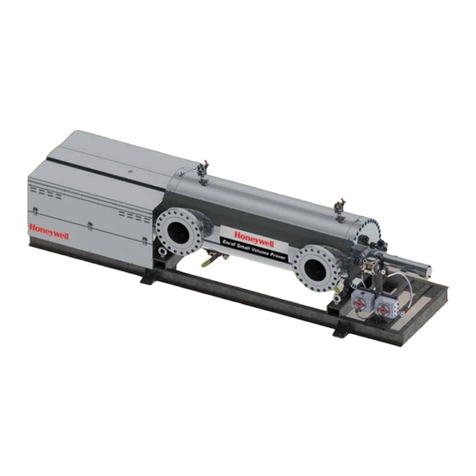
Honeywell Enraf User manual
Honeywell
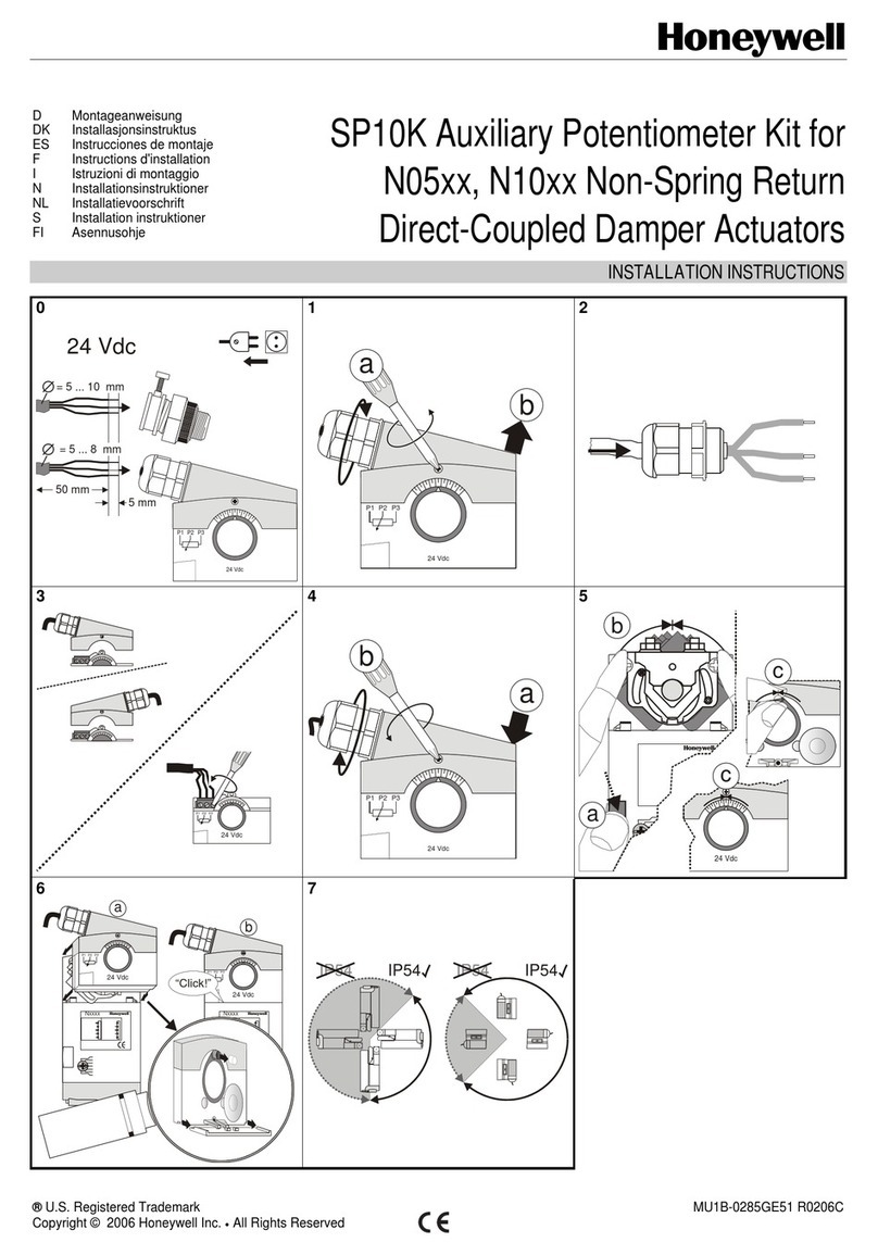
Honeywell SP10K User manual
Honeywell
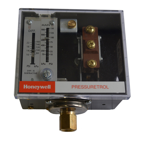
Honeywell Pressuretrol L404 Series User manual

Honeywell
Honeywell Touchpoint 1 User manual

Honeywell
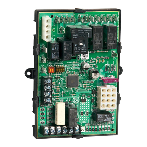
Honeywell HR 40 User manual
Honeywell
Honeywell S9200U1000 User manual
Honeywell
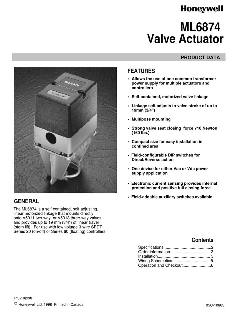
Honeywell ML6874 Operation manual
Popular Controllers manuals by other brands

Digiplex
Digiplex DGP-848 Programming guide

YASKAWA
YASKAWA SGM series user manual

Sinope
Sinope Calypso RM3500ZB installation guide

Isimet
Isimet DLA Series Style 2 Installation, Operations, Start-up and Maintenance Instructions

LSIS
LSIS sv-ip5a user manual

Airflow
Airflow Uno hab Installation and operating instructions
