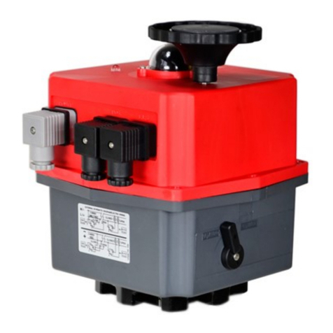
Valworx 5818 Series User manual

Doc: iom5818eps.0322 Cornelius, N.C. • USA www.valworx.com
IOM
5818
EPS
Installation Instructions
Electric Actuators with EPS Positioner–Explosion
Proof
5818 Series
APPLICABLE STANDARDS
ANTI EXPLOSION GRADE
The anti-explosion grade of these actuators is
Class 1, Division 1, Groups C & D T5
Ex db IIC T5 Gb Class 1 Zone 1
AEx db IIC T5 Gb
Where:
Class I –Hazard Class
Division I/ Zone 1 –Area Classification
db –Explosion Proof Type
II –Electrical Equipment design for explosive atmospheres (except colliery)
C –Magnitude of the explosion
T5 - Highest allowed surface temperature of the actuator (+55C)
Gb –Protection Grade
The grades of combustible gas, steam and temperature group are listed in
CSA 22.2 No 60079-0-2019, CSA 22.2 No 60079-1-2016, CSA 22.2 No
30-M1986(R2016), CSA 22.2 No 145-11(R2015), ANSI/UL 60079-2:2020,
ANSI/UL 1203-2013, ANSI/UL 674 Fifth Edition. It is the user’s responsibility
to ensure compatibility with the applicable regulations.
Models: 581856, 581857, 581876, 581877
READ THESE INSTRUCTIONS CAREFULLY BEFORE INSTALLING OR CONNECTING
POWER TO THE ACTUATOR. THE ACTUATOR MUST BE INSTALLED, COMMIS-
SIONED, OPERATED AND REPAIRED BY QUALIFIED PERSONNEL. COMPLY WITH
ALL APPLICABLE CODES, STANDARDS AND SAFETY REGULATIONS.
INTRODUCTION
This document provides installation, operation and maintenance instructions for
Valworx 5818 series electric actuators with EPS Postitioner. These actuators are
typically used to operate quarter-turn valves. Every actuator has been fully tested
prior to shipment to ensure trouble free operation.
CONDITIONS FOR USE
Failure to follow any of these conditions and warnings may void the warranty.
Valworx expressly disclaims any and all damages including consequential damages
resulting therefrom.
1. If the entry point, connecting pipe or contained cable exceeds 60°C the user
shall select the appropriately rated cable, cable gland and/or conductors in the
conduit and shall install per the IOM.
2. The minimum yield strength and minimum tensile strength of the explosion proof
conduit connector are 450MPa and 700MPa respectively.
3. The rated load is 50Nm (58185X series) and 200Nm (58187X series). Do not
exceed the rated load.
4. The lens plate shall not be loosened or removed at any time.
5. This unit contains the adhesives TSE3854DS-W and WCC-87 and cannot be used
in an atmosphere containing the following saturated vapors: Acetic Acid (glacial),
Acetone, Ammonium Hydroxide (20% by weight), ASTM reference fuel C,
Diethyl Ether, Ethyl Acetate, Ethylene Dichloride, Furfural, n-Hexane, Methyl Ethyl
Ketone, Methanol, 2-Nitropropane, and Toluene.
6. This explosion proof actuator is rated for T5. Ambient temperatures shall not
exceed -25°C ~ +55°C (-13°F ~ 131°F).
WARNING
1. To prevent the ignition of flammable gases, do not remove the cover while cir-
cuits are energized.
-avertissement–pour éviter l’inflammation des gaz inflammables, de vapeurs our
de poussiére, ne pas retirer le couvercle pendant que le circuit est sous tension
2. Explosion-proof sealing material shall be used to seal the explosion proof connect-
ing pipe, and the distance from the seal to the actuator shall not exceed 500mm.
-avertissement–un scellement doit étre installé a moins de 500 mm du boítier
3. The lens plate shall not be loosened or removed at any time.
4. The cable entry and connecting conduit shall not exceed 66°C(150.8°F) &
77°C(170.6°F) respectively.
5. Do not damage or otherwise make the nameplate illegible.
6. Avoid damaging or scratching the flameproof joints when servicing or installing
the actuator. Ensure the fastening screws connecting electric elements, junction
box cover, and motor box cover are appropriately tightened.
7. The electric motor cavity of this product is an independent explosion proof cavity.
Do not remove the motor cover or faying surface of the outlet lead.
8. This product must be grounded internally and externally. Ensure ground connec-
tions are secure and check regularly.
9. Wiring connections shall comply with applicable codes and standards. Connecting
cables shall have an explosion proof rating of at least Exdb IIC T5 Gb.
CAN/CSA C22.2 No.30-M1986
(Reaffirmed 2016)
CAN/CSA C22.2 No. 145-11
(Reaffirmed 2015)
CSA C22.2 No. 139-13
CSA C22.2 No.60079-0-2019
CSA C22.2 No.60079-1-2016
UL 674 Fifth Edition
UL 1203-2013
UL60079-0:2020
UL 60079-1:2020
UL 429 (Seventh Edition)
Explosion proof enclosures for use in
class I hazardous locations
Electric Motor and Generators for
Use in Hazardous (Classified)
locations
Electrically Operated Valves
Explosive atmospheres-Part 0: Equip-
ment-General requirements
Explosive atmospheres-Part 1: Equip-
ment protection by flameproof en-
closure “d”
Electric Motors and Generators for
Use in Hazardous (Classified) Loca-
tions
Explosion Proof and Dust Ignition
Proof Electrical Equipment for Use in
Hazardous (Classified) Locations
Explosive atmospheres-Part 0: Equip-
ment-General requirements
Explosive atmospheres-Part 1: Equip-
ment protection by flameproof en-
closure “d”
Electrically Operated Valves

2
STORAGE
Actuators should be stored in a clean, dry environment at all times. Do not install
the actuator outdoors or in humid environments without immediately supplying
power to activate the internal heater. The thermostatically controlled heater will
help prevent possible damage caused by condensation build up inside the actua-
tor.
CONSTRUCTION AND EXPLOSION PROOF REGULATIONS
The casing construction of each anti-explosion component of the actuator can
withstand the explosive pressure generated by an interior explosion caused by an
explosive gas mixture, and prevent transmission and explosion to the external
explosive gas atmosphere.
*A detailed drawing of the explosion proof construction can be found in Figure 8.
MOUNTING
The actuator can be mounted in any orientation. Allow enough room around
actuator for manual operation as well as any maintenance. Valves can be direct
mounted to the actuator using standard ISO5211 international mounting pad.
TEMPERATURE RATING
Ambient temperature range of the actuator is –13 to +131ºF (-25 to +55ºC).
Heat from the working medium (fluid) should not allow actuator to exceed these
temperature limits.
ENCLOSURE RATING
The rugged aluminum housing is rated Type 4X and IP67 weatherproof.
VISUAL POSITION INDICATOR
Actuators are supplied with a local visual valve position indicator. This indicator is
yellow and located on top of the actuator. Indicator will show the open and
closed (on-off) position of the quarter-turn actuator (valve).
ANTI-CONDENSATION HEATER
The actuator has a standard integral thermostatically controlled 4 watt anti-
condensation heater. Power should be maintained either in the open or closed
position to activate internal heater. This heater will help prevent condensation
build-up inside the actuator.
DUTY CYCLE AND MOTOR PROTECTION
The rugged 5818 series actuators are rated 70% duty cycle. Actuators are
equipped with thermal overload protection with automatic reset to guard against
over torque situations.
Doc: iom5818eps.0322 Cornelius, N.C. • USA www.valworx.com
IOM
5818
EPS
POSITION CONFIRMATION SWITCHES AND MECHANICAL STOPS
Two auxiliary limit switches are provided to confirm the actuator (valve) open
and closed positions. (use of these switches is optional). In addition, rotation of
the output drive is limited by adjustable mechanical stops. These stops are
preset at the factory, no adjustment required.
MANUAL OVERRIDE
Valworx 5818 series electric actuators have a manual override for use during
setup or loss of electrical power. To operate the manual override, first
“REMOVE ALL ELECTRICAL POWER TO THE ACTUATOR” then open the
manual override protective cover located on the side of the actuator. Insert a
hex wrench (provided) and rotate to open (counter-clockwise) or close as re-
quired.
MAINTENANCE
There are no internal parts that require regular maintenance. The gear drive is
pre-lubricated for life. The housing may be cleaned with warm soapy water (no
solvents). The actuator should be cycled at least once per month.
DO NOT PRESSURE WASH.
OPERATION
Valworx 5818 series electric actuators with EPS- Electronic Positioning System
provide an accurate valve positioning function whereby the movement of the
actuator is controlled by a 4-20mA input control signal. Any change in the
control input signal results in a corresponding and proportional change in the
position of the actuator drive output.
This is achieved with a unique built in electronic positioning module. The mod-
ule is fully potted to help protect the electronics from vibration and moisture.
An internal microprocessor on the EPS circuit board continuously monitors the
analog input and output signals and compares them to the physical position via
a precision potentiometer feedback system, moving the drive output as required
to balance the signals.
Figure 2
Visual position indicator
(do not remove)
Standard heater and
position confirmation limit
switches under this cover
WARNING: Disconnect electrical power prior to operating manual
override, removing covers or service
Standard ISO5211
valve mounting
interface
Electrical connection
via approved
explosion-proof
connection
Terminal box
cover
Figure 1 Figure 3
Figure 4

3
Doc: iom5818eps.0322 Cornelius, N.C. • USA www.valworx.com
ELECTRICAL WIRING
Confirm the actuator VOLTAGE is correct, then remove the terminal box cover and connect wiring to terminal strip according to appropri-
ate wiring diagram.
Wiring diagrams for each actuator are attached to the inside of the terminal box cover.
Input control signal type is 4-20mA. Actuator should have its own fused and isolated circuit. Do not connect actuators in parallel. Power
to actuator should be maintained to activate the internal heater. This heater will help prevent condensation build-up inside the actuator.
OPERATION
Valworx 5818 series electric actuators with EPS- Electronic Positioning System provide an accurate valve positioning function whereby
the movement of the actuator is controlled by a 4-20mA input control signal. Any change in the control input signal results in a corre-
sponding and proportional change in the position of the actuator drive output.
This is achieved with a unique built in electronic positioning module. The module is fully potted to help protect the electronics from vibra-
tion and moisture.
An internal microprocessor on the EPS circuit board continuously monitors the analog input and output signals and compares them to the
physical position via a precision potentiometer feedback system, moving the drive output as required to balance the signals
Before connecting power, confirm correct VOLTAGE is
being applied. Incorrect voltage may damage actuator and
void the warranty.
AC Voltage Wiring Diagram DC Voltage Wiring Diagram
AC Voltage Wiring:
1. AC power - Neutral
2. AC power - Line/Hot
3. Input control signal - Negative (-)
4. Input control signal - Positive (+)
5. Output monitoring signal - Negative (-)
6. Output monitoring signal - Positive (+)
DC Voltage Wiring:
1. DC power - Negative (-)
2. DC power - Positive (+)
3. Input control signal - Negative (-)
4. Input control signal - Positive (+)
5. Output monitoring signal - Negative (-)
6. Output monitoring signal - Positive (+)
NOTES: 1. Actuator should have its own fused and isolated circuit.
2. Do not wire actuators in parallel. 3. Output signal is 4-20mA. Use of
the output is optional.
FOR SUPPLY CONNECTIONS, USE WIRES SUITABLE FOR
AT LEAST 90°C (194°F) Employer Des Fils D'alimentation
Qui Conviennent Pour Au Moins 90°C
IOM
5818
EPS
EPS POSITIONER TECHNICAL DATA
Input Signal: 4-20mA
Output Signal: 4-20mA
Deadband: 0.5% to 5.0%
FOR SUPPLY CONNECTIONS, USE WIRES SUITABLE FOR
AT LEAST 90°C (194°F) Employer Des Fils D'alimentation
Qui Conviennent Pour Au Moins 90°C

4
Doc: iom5818eps.0322 Cornelius, N.C. • USA www.valworx.com
IOM
5818
EPS
1. Terminal strip
2. Selection switches (S-A, S-B)
L1. Power light (power on - green)
L2. Control Signal status light (red)
L3. Potentiometer status light (red)
L4. Over torque status light (red)
3. Manual Open control button
4. Manual Close control button
5. Set button (white)
6. Deadband Adjustment (factory
preset) - set actuator to manual mode
before altering - see chart below.
Internal Diagram
*Note: If any Red LEDs are ‘on’, there is a
malfunction.
Positioner Module
24 VDC MODELS 110 VAC MODELS
Control Module Control Module
Control Mode Selection Switch Setup S-A S-B
4-20mA Input
(default setting)*
*To change setup
from default setting,
power must first be
applied to actuator,
control signal OFF
Standard Auto Mode A
(default setting)
Actuator closed with 4mA signal, open with 20mA signal.
Stops with loss of control signal
1 2
Standard Auto Mode B Actuator closed with 4mA signal, open with 20mA signal.
Moves to closed position with loss of control signal
1 3
Standard Auto Mode C Actuator closed with 4mA signal, open with 20mA signal.
Moves to open position with loss of control signal
1 1
Reverse Acting Mode A Actuator open with 4mA signal, closed with 20mA signal.
Stops with loss of control signal
3 2
Reverse Acting Mode B Actuator open with 4mA signal, closed with 20mA signal.
Moves to closed position with loss of control signal
3 3
Reverse Acting Mode C Actuator open with 4mA signal, closed with 20mA signal.
Moves to open position with loss of control signal
3 1
Manual operation of
actuator using control
button operation
Manual Mode - Open or
Closed
Manually move the actuator to open position using OPEN con-
trol button. Manually move the actuator to closed position
using CLOSED control button. Do not hold OPEN & CLOSED
2 2
OPEN/SHUT POSITION CALIBRATION
ALL ACTUATORS ARE CALIBRATED AND TESTED AT THE FACTORY. NO ADJUSTMENTS REQUIRED FOR MOST APPLICATIONS If recalibration is required, follow
these steps: Supply correct power to the actuator. Set switches to manual mode as shown below. Manually operate actuator using chart below. Once new desired
“Open” or “Closed” position is reached, hold down both the matching manual control button for the position you wish to set AND the White “SET” button simultane-
ously until the L2 red light comes on - then release both buttons. The position will now be set when you switch S-A back to original position.
L1
L2
L3
L4
2 6
1
3
4
5

5
Doc: iom5818eps.0322 Cornelius, N.C. • USA www.valworx.com
IOM
5818
EPS
CONDUIT AND CABLE INSTALLATION
1. Remove the explosion-proof plug and tighten the corresponding explosion
proof connecting pipe together with the inlet lead cable
Note: Explosion-proof sealing material shall be filled into the explosion proof
connecting pipe, and the distance from the filling position to the actuator shall
not be greater than 500mm as shown in Fig 5.
Figure 5
2. Connect the leads per the appropriate wiring diagram.
Note: In order to meet explosion proof requirements, the connectors and hole
plugging materials need to meet the requirements of the CSA explosion proof
standards and be installed correctly.
3. Ensure the interior and exterior ground connections are properly made.
Note: the connection method in this manual is for explosion-proof pipe. The
user may choose other connection methods provided they meet all applicable
explosion-proof requirements.
INSTALLATION WITH BRACKETS AND COUPLERS
Installation with Brackets and Couplers
1.Brackets and couplers shall meet the dimensional tolerances as shown In Fig. 6
2.The coupler stem tolerances should ensure minimal backlash during operation.
3.The positional tolerances of the coupler should ensure they do not exceed the
stroke adjustment limits of the actuator.
Figure 6
INSTALLATION WITH BRACKETS AND COUPLERS (CONTINUED)
Figure 7

6
Doc: iom5818eps.0322 Cornelius, N.C. • USA www.valworx.com
IOM
5818
EPS
Figure 8
CONSTRUCTION DRAWINGS OF EXPLOSION PROOF TYPE
No. Part Name No. Part Name
1 Motor cover 6 Junction Box cover
2 Electric motor rotor
shaft
7 Electric elements cover
3 Box body 8 “O” Washer seal
4 Explosion-proof plug 9 Exd lens
5 “O” washer seal 10 Output shaft
This manual suits for next models
4
Table of contents
Other Valworx Controllers manuals
Popular Controllers manuals by other brands

BZ PRODUCTS
BZ PRODUCTS M20+ installation manual

Silicon Graphics
Silicon Graphics InfiniteStorage 5600 Quick install guide

Feig Electronic
Feig Electronic TST FUF2 Series Assembly instructions

Coolmay
Coolmay FX3GC Series user manual

1A Profi Handels
1A Profi Handels AQUA-21 instruction manual

Rockwell Automation
Rockwell Automation Allen-Bradley DriveLogix 5730 user manual