FAURE HERMAN HELIFLU TZN User manual

HELIFLUTM TZN
User’s Manual
FAURE HERMAN
Route de Bonnétable
BP 20154 – 72406 La Ferté Bernard
Cedex France
Tel : + (0)2 4 60 28 60
Fax : + (0)2 4 60 28 70
E-mail : fhprojects@idexcorp.com
FAURE HERMAN METER
4702 N Sam Houston Pkwy West
Suite 100
Houston, TX 77086 (U.S.A)
Tel : +1 71 62 0808
Fax : +1 71 62 2 2
E-mail: FHH-Sales@idexcorp.com
FAURE HERMAN
Office #7 8, Building #6EB
Dubai Airport Freezone (DAFZA)
Dubai (U.A.E)
Tel : +971 4260 0 81
Fax : +971 4260 0 19
Email : fhsalesme@idexcorp.com
www.faureherman.com

Page 2 / 37
Ta le of Contents
Chapter 1: Introduction to TZN Meters (STD & CUS) ...........................................................................................
Chapter 2: Meter Components by Meter Size ...................................................................................................... 4
Chapter : Equipment Receipt, Storage and Handling ......................................................................................... 6
Chapter 4: Installation and Operation ................................................................................................................... 7
Chapter 5: Commissioning ................................................................................................................................... 1
Chapter 6: Maintenance ....................................................................................................................................... 14
Chapter 7: Troubleshooting ................................................................................................................................. 14
Chapter 8: Replacement – Repair ........................................................................................................................ 15
Chapter 9: Equipment removal ............................................................................................................................ 19
Appendix 1 – Alternative configurations ............................................................................................................. 20
Appendix 2 – Meter drawings by size and type .................................................................................................. 21
Appendix 2 - K-factor – Flowrate/Frequency ...................................................................................................... 27
Appendix - Operating restrictions & Special recommendations .................................................................... 28
Safety Consideration ............................................................................................................................................. 29
Ta le of Figures
Figure 1. Mechanics of Signal Generation of Helical Turbines ............................................................................
Figure 2. Meter body types by size ......................................................................................................................... 4
Figure . Cartridge types by size ............................................................................................................................. 5
Figure 4. Complete Meter run with upstream/downstream spool pieces and flow conditioner ...................... 6
Figure 5. Proper lifting technique for meters > 6 inches ...................................................................................... 7
Figure 6. Proper pipe alignment for meter installation......................................................................................... 8
Figure 7. Recommended tightening torque for Klingersil gasket type ................................................................ 9
Figure 8. Factory wiring of pickup coil: with and without preamp ................................................................... 11
Figure 9. Types of preamplifiers........................................................................................................................... 11
Figure 10. Typical wiring diagram for 2 wires FH71with Input Impedance greater than 10 kΩ ..................... 12
Figure 11. Typical wiring diagram for wires FH71 (Open Collector) ............................................................... 12
Figure 12. Example wiring diagram for wires FH71 (Open Collector) with isolator ..................................... 12
Figure 1 . Typical 2 wires FH71 connection to SPIRIT Flow-X Flow Computer ................................................ 1
Figure 14. Typical wires FH71 connection to Emerson S600 FloBoss Flow Computer ................................. 1
Figure 15. Typical 2 wires FH71 connection to OMNI 000/6000 Flow Computer .......................................... 1
Figure 16. Illustration of Preamplifier Replacement .......................................................................................... 15
Figure 17. Illustration of Removal of Metal Ring type pickup coil ..................................................................... 16
Figure 18. Illustration of Removal of Engineered Polymer Ring type pickup coil ............................................ 17
Figure 19. Cartridge replacement – meters < ’’ ................................................................................................. 17
Figure 20. Cartridge replacement for meters 4’’ - 14’’ ....................................................................................... 18
Figure 21. Cartridge replacement – meters >16’’ ............................................................................................... 18
Figure 22. CUS Cartridge removal ........................................................................................................................ 19
Figure 2 . TZN with local totalizer ....................................................................................................................... 20
Figure 24. TZN with thermal extensions .............................................................................................................. 20
Figure 25. TZN with pulse outputs .................................................................................................................... 20
Figure 26. Nominal Size STD ≤ '' ......................................................................................................................... 21
Figure 27. Nominal Size CUS ≤ '' ......................................................................................................................... 22
Figure 28. Nominal Size STD 4''-14'' ..................................................................................................................... 22
Figure 29. Nominal Size CUS 4''-14'' .................................................................................................................... 24
Figure 0. Nominal Size STD > 16'' ....................................................................................................................... 25
Figure 1. Nominal Size CUS > 16''....................................................................................................................... 26
Page 3 / 37
Chapter 1: Introduction to TZN Meters (STD & CUS)
The simple, rugged construction of TZN turbine meters provides excellent accuracy and
measurement repeatability for a wide range of industrial applications. All TZN flow meters, both
STD and CUS, are designed to provide high quality liquid volume measurement across a wide range
of viscosities (0. to >1,000 cSt).
The TZN CUS model was specifically developed to measure fluids containing fibers, paraffin, or
DRA (Drag Reducing Agents). The patented TZN CUS shaft and bearing system minimizes negative
impacts of these substances on measurement accuracy.
The removable measurement sub assembly (also referred to as ‘cartridge’) design allows
pressure to be equalized between the cartridge and meter body, thus eliminating sensitivity to fluid
pressure variations. Additional benefits of this design enables factory calibration of the cartridge,
independent of the meter body, which allows rotation of cartridges in challenging operational
environments (remote installations, limited access of onsite site provers, high pressure
applications, etc.), as well as selecting a different cartridge to meet changes in operational flow
rates (within calibrated flow parameters). This can significantly reduce operational downtime and
maintenance costs.
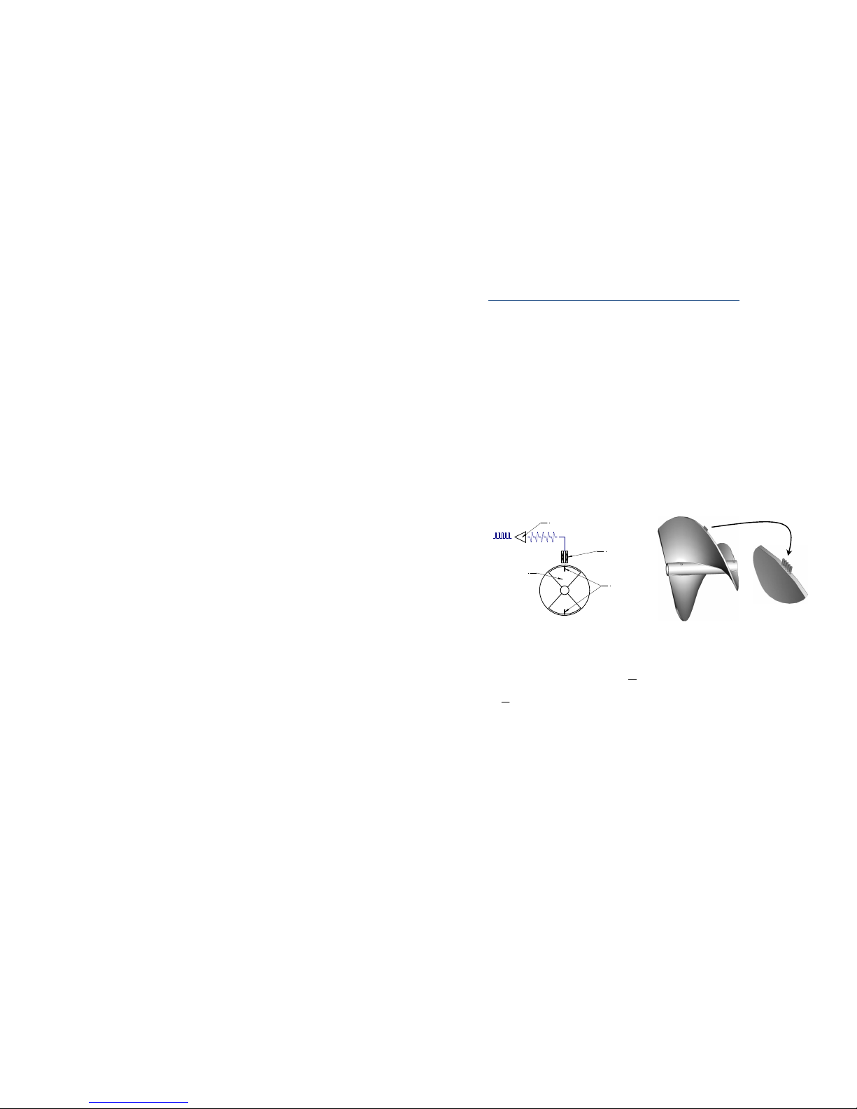
Generation of Signal
The operating principle of helical turbine flow meters is based on the electromagnetic field
generated by the rotational velocity of magnets imbedded in blades of the helical rotor passing by
a pick-up coil positioned in the flowmeter body.
Dual blade
helical rotor
Coil
Preamplifier (optional)
Embedded
magnets
Figure 1
. Mechanics of Signal Generation of Helical Tur ines
Measuring the electrical signal generated allows calculation of the liquid flow rate flowing into the
pipe through the following expression:
600,
Kf
F
Q×=
, and the transferred volume through:
Kf
N
V=.
With Q Instantaneous flow rate in m
/h [l/min, GPM, BPH …]
F Output signal frequency in Hz
Kf Measurement cartridge Kfactor in pulses/m
[p/l, p/USG, p/bbl …]
Kfactor is established during measurement cartridge calibration.
V Volume in m
[litres, Gallons, Bbls]
N Number of pulses
Page 4 / 37
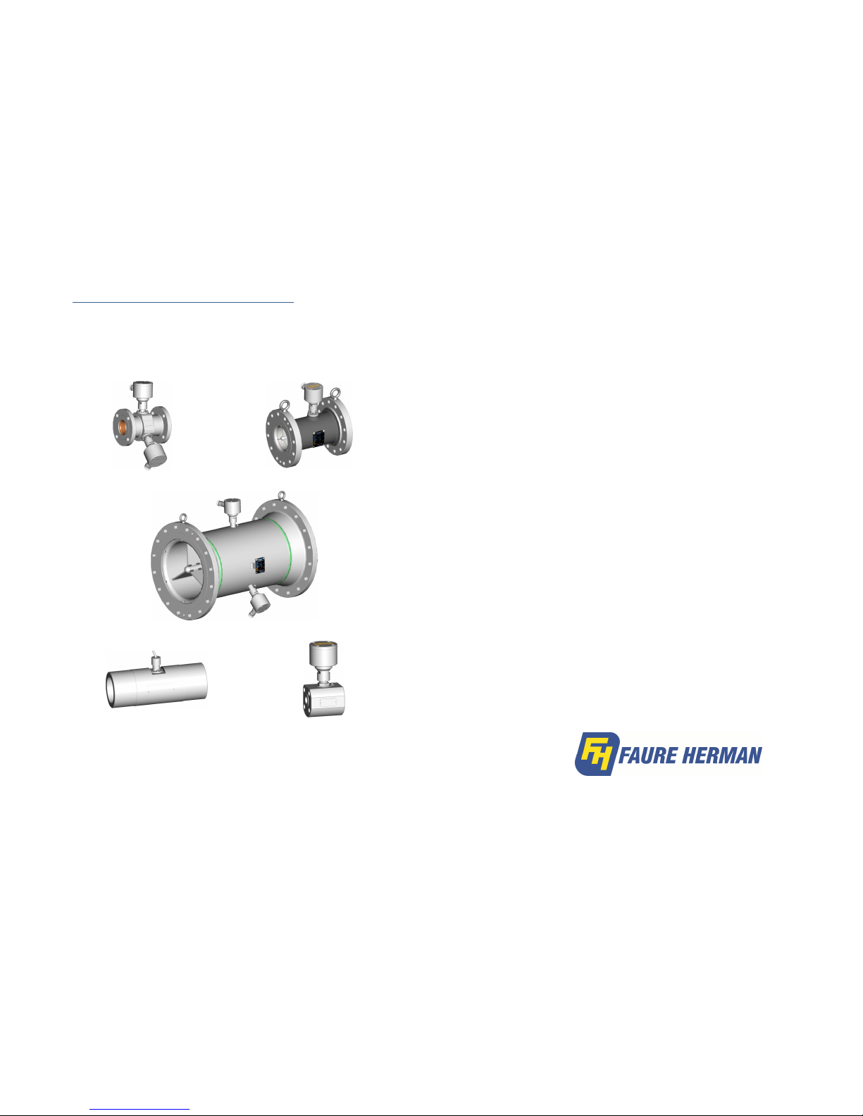
Chapter 2: Meter Components y Meter Size
TZN flowmeters include the following components:
1. Body
2. Measuring sub-assembly / cartridge
. Inlet ring
4. Detection sub-assembly / Electronics enclosure
5. Flow conditioner (Optional)
½ to ” TZN
4 to 14” TZN
16 to 20” TZN
Threaded type TZN (Size ≤ 2”)
Wafer style (Size ≤ 2”)
Figure 2. Meter ody types y size
Page 37 / 37
TEC 02
-
05
-
01 EN Rev A
(05/2017)

Page 36 / 37
Corrosion erosion
Choose proper materials.
Apply an additional corrosion
thickness. Application of painting systems adapted to the
environment.
Corrosion cavitation Choose proper materials. This is metrological equipment, the
user must set up devices to avoid cavitation.
Abrasion
Choose proper materials
–
Apply an additional corrosion
thickness. It remains under user responsibility to periodically
check the condition of the equipment.
ATEX Recommendations
When applicable, this equipment is ATEX certified and complies with the essential Health and Safety
requirements relating to the design and construction of equipment intended for use in potentially explosive
atmospheres (2014/ 4/EU Directive).
For safe operation, please ensure that this equipment is used in total compliance with the instructions given on
the ATEX certificate and nameplate. Please consult the user manuals, equipment installation and maintenance
manuals regarding the various parts used in this device. This equipment must be installed and serviced by trained,
specialized staff who understand the languages used in the manual.
If you require a manual or any additional information, please contact the FAURE HERMAN Customer support
team:
FAURE HERMAN - Route de Bonnétable – 72400 La Ferté Bernard – France
+ (0)2 4 60 28 60 -
+ (0)2 4 60 28 70 - support@faureherman.zendesk.com
Page 5 / 37
Meter Body
The meter body is most commonly made of carbon steel or stainless steel (AISI 16/ 16L or
equivalent); other materials are available upon request (Duplex, Hastelloy …).
The meter body contains a removable cartridge. Depending upon meter size and operational
preferences, the body can be fitted with one, two or three bosses, allowing generation of single or
dual pulse signals to flow computer, as well as the addition of a localized readout via a totalizer if
desired. The position of the electronic enclosures is arranged so that pulse trains delivered by the 2
coils are 90° out of phase.
The meter body will contain the following markings:
•An arrow indicating the direction of fluid flow
•A manufacturer's nameplate with specific equipment identification
NOTE: TZN CUS cartridges are distinguished from TZN STD versions by their specific fixed rotor
shaft and the presence of bearing supports in the crosspieces.
Measurement Cartridge Types y Size
Nominal sizes ≤ " The cartridge is centered and
fastened into the body by means of an upstream
stainless steel threaded ring. NOTE: on older models, the
ring is part of the cartridge.
Nominal sizes 4” ≤ 14” The
cartridge is centered and
fastened into the body by
means of an upstream stainless
steel ring fixed with screws.
Nominal sizes ≥ 16" The piece cartridge is centered and fastened into the body by means of
upstream and downstream stainless steel cross pieces containing the rotor. The outer rings are
fixed into the meter body to hold the cartridge in place with screws.
Figure 3.
Cartridge types y size
Page 6 / 37
Detection Su -assem ly / Electronic Enclosure
The detection sub-assembly is housed in a flame-proof box which permits the use of the
flowmeter in electrically classified areas (UL/cUL Class 1 Div 1 Group C & D; ATEX/IECEx II1G – IIC
T6). The electronic enclosure integrates the following elements:
•A pick up coil housed in the bottom of each boss and kept in position by means of a ring
•A coil/pre-amplifier connection cable
•An optional pre-amplifier which allows operators to significantly increase the maximum
distance between the flowmeter and the electronic display and/or flow computer (up to
5,000 meters/16,000 ft)
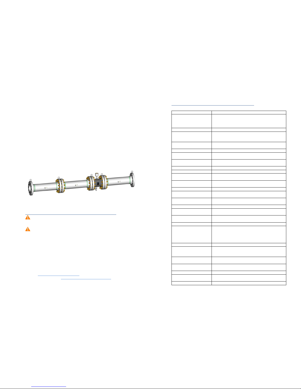
Flow Conditioning
According to API MPMS Chapter 5. and ISO 2715, “The performance of turbine meters is
affected by swirl and non-uniform velocity profiles that are induced by upstream and downstream
piping configurations, valves, strainers, pumps, fittings, joint misalignment, protruding gaskets,
welding projections, or other obstructions. Flow conditioning shall be used to overcome the
adverse effects of swirl and non-uniform velocity profiles on turbine meter performance.”
Faure Herman can supply the flow conditioning assembly which integrates upstream piping,
flow conditioning element (plate, straightening vanes, etc.) and downstream piping (to be utilized
at time of meter calibration).
Figure 4. Complete Meter run with upstream/downstream spool pieces and flow conditioner
Chapter 3: Equipment Receipt, Storage and Handling
Upon receipt of the TZN turbine meter, inspect the packing case for any shipping damage. The
meter must be carefully removed from the packing case and inspected for potential damage or
missing parts (including documentation)
Before installation, the unit should remain stored in its original packing, protected against
adverse weather conditions, and maintained at temperatures between -20 /+70 °C (-4 /+158 °F).
If the meter isn’t installed within a month, FH recommends maintaining the metering assembly
in an inerted atmosphere (nitrogen) or fluid filled state (light hydrocarbons). Please check
applicable regulation to ensure that all calibration requirements have been met.
Prior to installing the TZN, visually inspect the turbine meter; pay particular attention to name
plate (check for serial number, process conditions, direction of flow …), flange rating and general
conditions.
Should the product be damaged or documents missing, please contact the Faure Herman
Worldwide Customer Support & Service via phone, email or website:
Hotlines: +1 (71 ) 597 4827 (North America)
+ (0)2 4 60 28 55
Email: su[email protected]m
Online Assistance website: https://faureherman.zendesk.com/hc/en-us
Page 35 / 37
Risk analysis according to Directive 2014/68/EU
Suita le resistance
Requirements
Excess temperature and
pressure
Temperatures and pressure limits should be considered during
the design phase.
The limitations are indicated on the equipment; the user is
responsible to set up equipment properly.
Wind / Snow influence
NA:
Without influence considering the small surface
areas
Earthquake
The equipment is not intended for use in a seismic zone. If
operated as such, it is the responsibility of the user to provide
adapted devices.
Support, binding and piping
reaction
The equipment is
designed to be
joined
to other piping
;
it
does not have its own supports.
Thermal fatigue
Design
c
hoice of materials follow
s
ASME B 1. .
Mechanical fatigue
This is metrological equipment; i
t
is the
user’s
responsibility to
install properly to avoid mechanical stress.
Vibration This is metrological equipment; it is the user’s responsibility to
install
away from
sources of vibration.
Handling and operation
Comments
Closing and opening
NA: t
he equipment does not have
an
aperture or closure.
Dangerous emissions from
valves
NA: the equipment does not have a valve.
Access to the inside
NA: t
he equipment does not have access (inspection hatch,
manhole).
Surface temperature
T
he user
is responsible for indication of
hot surfaces.
Decomposition of unstable fluid NA: The equipment is used for the transfer of fluid not
storage.
Handling
E
quipment
>
0kg is equipped with lifting rings
for safe
handling.
Draining and venting
Comments
Pressure wave
This is sensitive metrological equipment; i
t
is the
user’s
responsibility to install properly to avoid pressure waves.
Vacuum collapse
Minimal service pressure of 0 b
ar.g indicated on the plate.
This
equipment is not
designed
to work
under
vacuum.
Corrosion and chemical attack
Comments
Uniformly generalized
Consideration of corrosion
thickness.
Choose proper materials and application of painting systems
adapted to the environment.
It remains under user responsibility to periodically check the
condition of its installation.
Selective
Choose proper materials
Galvanic
Choose proper
materials and review compatibility of
materials. It is the user’s responsibility to set up adapted
devices, groun
ding
strap
s
, cathodic protection…
By differential aeration
Choose proper materials
–
Maintain the equipment full of
fluid.
By puncture, crev
ice,
intergranular
Choose proper materials. Review c
ompliance with NACE
MR0175 requirements if applicable.
Ammonia
Choose proper materials
Under stress
Choose proper materials. Review c
ompliance with NACE
MR0175 requirements if applicable.
Wear
Comments
Page 34 / 37
Page 7 / 37
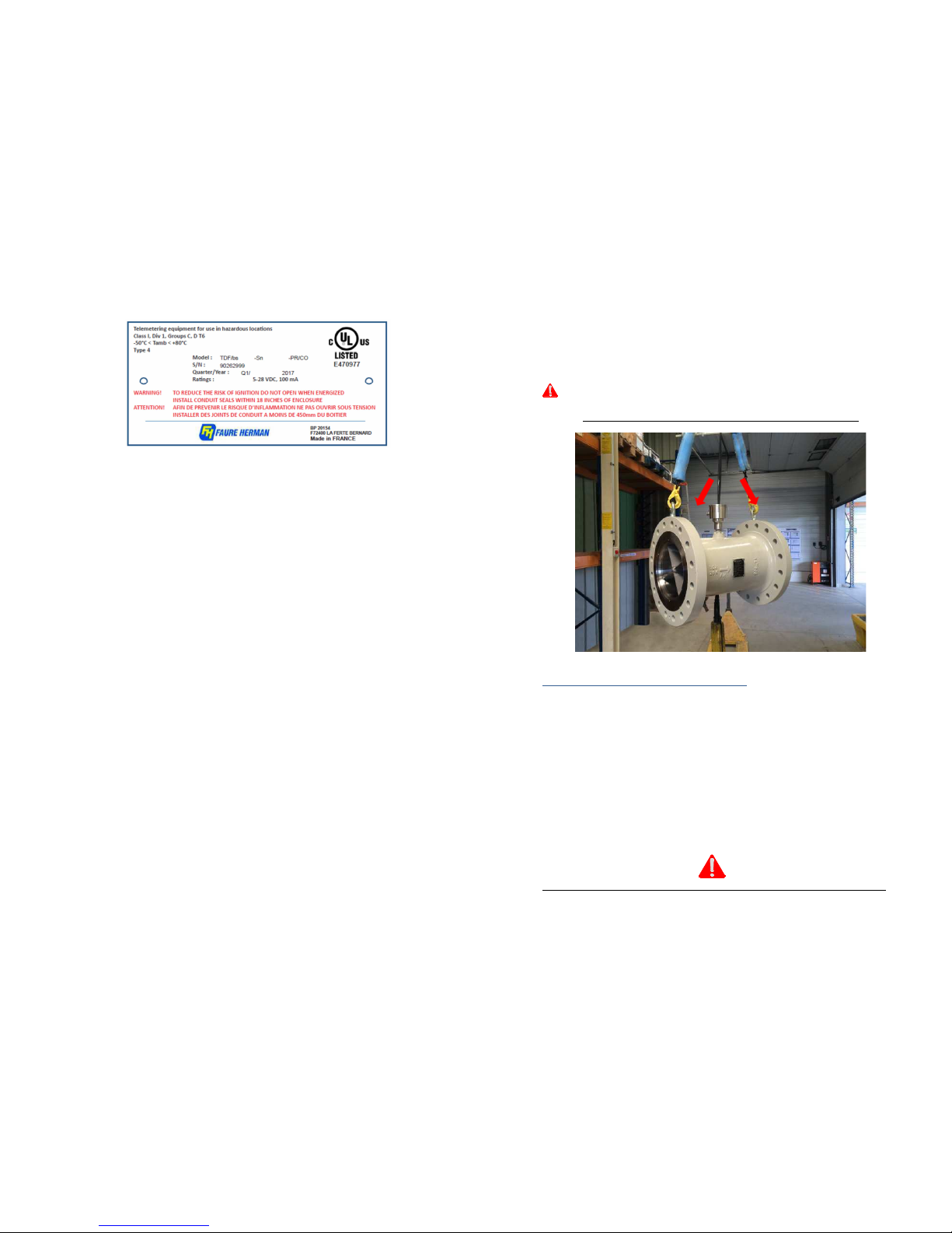
Handling recommendations: Meter sizes
≥
6"(DN 150) or weighing > 5 kg [77
lbs]
The TZN must be carefully handled with lifting rings (when applicable) or with straps on both
sides of the body.
Electronic detection system enclosures must not e used for lifting.
Figure 5. Proper lifting technique for meters > 6 inches
Chapter 4: Installation and Operation
TZN turbine flowmeters can be installed horizontally or vertically (ascending flow) provided the
flow direction indicated on the cartridge and meter body are followed.
For custody transfer applications, turbine flowmeters require the integration of a minimum
upstream pipe length at least equal to 10 times the pipe diameter and at least equal to 5 times the
pipe diameter downstream.
Mechanical Preparation of Pipe Prior to Meter Installation
Prior to flowmeter installation on the pipe, check the following to ensure proper operation:
•Cleanliness of the pipe upstream from the flowmeter
•Flow direction indicated by an arrow on the nameplate
•Correspondence between flanges and joint faces, on pipe and flowmeter sides
•Flowmeter alignment with upstream and downstream pipes and absence of obstacles
preventing the correct liquid flow (gaskets, …)
•Follow recommended tightening torques in Appendix IV when bolting flanges
•Position of electrical connections to avoid binding
As a measuring instrument, tur ine flowmeters must e handled with care.

Page 8 / 37
Meter installation
Before installation, keep the equipment in its original packing, sheltered from bad weather and
possible impacts.
The meter should be installed in the measurement line with proper alignment of upstream and
downstream flanges so that stress on the equipment body is avoided.
Figure 6. Proper pipe alignment for meter installation
The equipment must be installed by using the proper tools (wrenches):
•Never use a hammer
•Use impact wrenches with caution; pay attention to torque recommendations
•Specific tools can be used, when necessary, for the spacing between flanges.
If used, leave lift mechanisms in place until all bolts have been tightened.
Gaskets
Check to ensure that the proper gaskets are installed according to flange type: ASME B16.20 and
ASME B16.21 or NF EN 1514 and NF EN 12560 standards.
NOTE: Spiral wound gaskets are forbidden for flanges rated below class 00 or PN 6 .
Never reuse gaskets.
Page 33 / 37
1
Category
A
rea in which an atmosphere at risk of explosion as
a mixture of air
and inflammable gases, vapors or mists is continuously or frequently
present or present
for long periods.
G
Gas/Dust
Gas
Ex
Electrical device
d
Type of protection
Flameproof
II
Gas group
Surface above ground industries
C
Gas subgroup
Most easily ignited e.g. hydrogen
or
acetylene
Gb
Protection level
Equipment for use in explosive atmospheres due to the presence of
gas, with a 'high' level of protection that is not the source of ignition in
normal operation or when subject to expected malfunctions, although
not on a regular basis.
T6
85°C
-50°C
≤
Fluid Temperature
≤
+80°C
UL & cUL Installation
Magnetic sensor assemblies are UL and cUL certified for use in Class I, Div 1, Groups C and D
hazardous locations, with several combinations of coils and preamps.
Ambient temperature must remain within -50 and 80°C. An optional thermal extension can be
used to handle liquids heated up to 150°C.

Page 32 / 37
ATEX Electrical Component Criteria
Electrical components are covered LCIE 0 ATEX 62 0X certification which allows use in
intrinsically safe or flameproof applications.
ATEX Intrinsically Safe Data Ta le and Tag Example
The intrinsically safe model certification depends on whether a preamplifier is used and the
temperature range of application (Table 2).
•without preamplifier II 1 G EEx ia IIC T6 to T ; ambient temperature (Ta) between -20 &
+180°C
•with FH71 preamplifier
II 1 G EEx ia IIC T6 to T5; ambient temperature (Ta) between -20 &
+80°C
Table 2.
ATEX mark
II
Equipment Group
Equipment for places with a potentially explosive atmosphere, other
than mines susceptible to firedamp.
1
Category
A
rea in which an atmosphere at risk of explosion as
a mixture of air
and inflammable gases, vapors or mists is continuously or frequently
present or present
for long periods.
G
Gas/Dust
Gas
Ex
Electrical device
ia Type of protection Intrinsically safe
II
Gas group
Surface above ground industries
C
Gas subgroup
Most easily ignited e.g. hydrogen or
acetylene
T6 85°C; Ta
≤
80°C
T5 100°C; Ta
≤
95°C
T4 1 5°C; Ta
≤
1 0°C
T 200°C; Ta
≤
180°C
Additional parameters applying to ATEX Intrinsically Safe certification
Without
preamplifier
Ui
≤
10 V Ii
≤
2 mA Ri ≥ ,420 Ω Ci
≅
0 Li
≤
.2 H
With FH71 preamplifier Ui ≤ 28 V Ii ≤ 150 mA Pi ≤ 1 W Ci ≅ 0 Li
≤
0
ATEX & IEC Ex Flameproof Data Ta le and Tag Example
The flameproof models are certified II 1 G Ex d IIC T6 Gb & IECEx LCI 12.001 X. Ambient
temperature (Ta) must remain between -50 and + 60°C.
Table
ATEX mark
II
Equipment Group
Equipment for places with a potentially explosive atmosphere, other
than mines susceptible to fire damp.
Page 9 / 37
Flange olts
The material of flange bolts shall be chosen in ASTM A 19 B7 (bolts) and ASTM A 194 2H
(nuts) according to ASME B16.5 standard for temperature between -45°C and +480°C.
Tightening torque
If the flowmeter is equipped with a flow straightener, the bolts must be checked and
retightened before commissioning. A label affixed to the flanges calls attention to this requirement.
Bolt size and tightening torque
–
non coated
Bolt size and tightening torque
-
coated
M
N.m
NPS
ft
-
lb
M
N.m
NPS
ft
-
lb
14
110
1/2
60
14
85
1/2
45
16
160
5/8
120
16
1 0
5/8
90
20
50
/4
210
20
250
/4
160
24
550
7/8
50
24
450
7/8
250
27
800
1
500
27
650
1
400
0
1,150
1 1/8
750
0
900
1 1/8
550
1,550
1 ¼
1,050
1,200
1 ¼
800
6 2,040 1
⅜
1,400 6 1,600 1
⅜
1,050
9
2,650
1 ½
1,800
9
2,050
1 ½
1,400
42
, 50
1
⅝
2, 50
42
2,550
1
⅝
1,800
Figure 7. Recommended tightening torque for Klingersil gasket type
Condition of Liquids Measured
Flowmeter life duration and measurement reliability can be seriously impacted by the
presence of gas and/or solid particles in the flowing liquid.
The presence of gas, in the form of bubbles or emulsions, can cause serious degradation of
measurement performance. Gas "pockets" between two liquid sections can destroy the rotor
bearings, leading to serious measurement errors and/or damage to the cartridge assembly.
To ensure accurate measurement and minimize possibility of damage, FH recommends
eliminating the possibility of gas injection upstream from the measurement point and providing,
when required, a draining or degassing system upstream from the flowmeter. We recommend
positioning the flowmeter to minimize the possibility of gas pocket formation resulting from
contraction of volumes during an interruption of flow.
The presence of small-sized solid particles within the flowing liquid may result in a gradual
deterioration of the flowmeter fixed or mobile elements (bearing support cross pieces, bearing,
rotor), which can lead to a gradual deterioration of performance. Larger solids can cause significant
damage requiring replacement of these parts (bearing support cross pieces, bearing, and/or rotor).

Page 10 / 37
Recommended Strainer Size y Meter
Protection of turbine meter (and associated instrumentation) can be critical during new
installations start-up and when a system is restarted after heavy work upstream of the meter run.
To minimize the risk of solid particle injection upstream from the measurement point, we
recommend installation of a strainer with mesh sizes as listed in the table below:
TZN Model (CUS & STD)
Recommended
Filtration
TZN Model
mm
m
/h (max)
inches
BPH (max)
(mm)
MESH
TZN 16
-
012
TZN 16-025 16
0.12
0.25 1/2
0.75
1.5 0.15 100
TZN 20-05
TZN 20-01 20 0.5
1 /4 .1
6. 0. 55 45
TZN 25-2
TZN 25-
TZN 25-5
TZN 25-10
25
2
5
10
1
1
20
0
6
0.425 40
TZN 2
-
8
TZN 2-12
TZN 2-15
TZN 2-20
2
8
12
15
20
1 1/4
50
75
94
126 0.5
5
TZN 40
-
8
TZN 40-12
TZN 40-15
TZN 40-20
TZN 40-40
40
8
12
15
20
40
1 1/2
50
75
94
126
250
TZN 50- 0
TZN 50-50
TZN 50-70
50
0
50
70
2
190
20
440
0.85 20
TZN 80-70
TZN 80-110
TZN 80-150
80
70
110
150
440
690
94
1.4
14
TZN 100-200
TZN 100- 00 100 200
00 4 1,260
1,890 1.7 12
TZN 150-400
TZN 150-600 150 400
600 6 2,520
,770 2. 6 8
TZN 200-800
TZN 200-1000
TZN 200-1200
200
800
1,000
1,200
8
5,0 0
6,290
7,550
2.8 7
TZN 250-1200
TZN 250-2000 250 1,200
2,000 10 7,550
12,600 . 5 6
TZN 00-2400
TZN 00- 000 00 2,400
,000 12 15,100
18,900
TZN 50- 500 50 ,500 14 22,000
4 5
TZN 400-4000
TZN 400-4500 400 4,000
4,500 16 25,200
28, 00
TZN 450-4800
TZN 450-5500 450 4,800
5,500 18 0,200
4,600
TZN 500-6000 500 6,000 20 7,800 4.75 4
IMPORTANT: After a period of critical monitoring, the filtration degree can be relaxed to reduce
strainer maintenance and pressure losses, e.g. MESH 6 to MESH 4 on a 12” meter (consult
manufacturer).
Page 31 / 37
ATEX Non electrical certification Data Ta le and Tag Example
The mechanical part is a non-electrical part as defined under the certificate LCIE 05 ATEX
60 5X. This equipment is manufactured with a protective system as defined by European standards
NF EN 1 46 -1 and 1 46 -5 and is certified II 2 G c T6 to T1 within fluid temperatures between -
50 and + 50 °C (Table 1).
Table 1.
ATEX mark
II Group
Equipment for pl
aces with a potentially explosive atmosphere, other
than mines susceptible to firedamp.
2 Category
E
quipment designed to be capable of functioning in conformity with
the operational parameters established by the manufacturer and
ensuring a high level of protection.
Equipment in this category is intended for use in areas in which
explosive atmospheres caused by mixtures of air and gases, vapors or
mists or by air/dusts mixtures are likely to occur.
The means of protection relating to equipment in this category
ensures the requisite level of protection, even in the event of
frequently occurring disturbances or equipment faults which are
normally taken into account.
G
Gas/Dust
Gas
c
Type of protection
Protection by
constructional safety
“safe by design”.
T6 85°C -50°C
≤
Fluid Temperature
≤
+80°C
T5
100°C
+80°C
<
Fluid Temperature
≤
+95°C
T4
1 5°C
+95°C
<
Fluid Temperature
≤
+1 0°C
T 200°C +1 0°C
<
Fluid Temperature
≤
+195°C
T2
00°C
+195°C
<
Fluid Temperature
≤
+290°C
T1
450°C
+290°C
<
Fluid Temperature
≤
+ 50°C
NOTE: For models containing aluminum parts (rotor), fluid temperatures are limited from -50 to
+100°C
Complete unit ID plate
(mechanical & electrical)
Page 30 / 37
If the flowmeter is equipped with lifting rings, they must be used. The flowmeter must never
be handled, lifted or secured by the electronic enclosures.
Unpacking
Upon receipt of the TZN turbine meter, inspect the packing case for any shipping damage. The
meter must be carefully removed from the packing case and inspected for potential damage or
missing parts (including documentation). Protective devices such as end caps must be removed
prior to installation.
Storage
If the flowmeter is not installed as soon as it is received, it must be stored and protected from
the elements. In case of extended storage (more than a year), check applicable regulation to ensure
that all calibration requirements have been met.
Return
Contact Faure Herman prior to any return. If the flowmeter has been used with hazardous,
corrosive, or toxic substances, the operator must make sure that it has been correctly rinsed,
cleaned, and decontaminated before being returned to Faure Herman.
ATEX & IEC Ex Installation
This equipment is ATEX and IEC Ex certified and complies with the essential Health and Safety
requirements relating to the design and construction of equipment intended for use in potentially
explosive atmospheres (2014/ 4/EU Directive).
Please ensure this equipment is used in total compliance with the instructions given on the
ATEX certificate and nameplate. Consult the user manuals, as well as equipment installation and
maintenance manuals for this device to ensure safe operation of this equipment.
This equipment contains non-electrical and electrical components which are both ATEX
certified relating to the design and construction of equipment intended for use in potentially
explosive atmospheres (Directive 2014/ 4/UE).
General Safety Information
The meter must be de-energized for all installation and maintenance activities.
For safe operation, the equipment must be used in compliance with its’ ATEX / IEC Ex
certificate and nameplate criteria. Observe all instructions for equipment and component parts
contained in user manual.
The equipment must be installed and operated only in areas complying with its hazardous
protection rating as specified on the plate attached to the meter.
If the equipment is connected to ancillary devices, check to ensure the electrical protection
systems are fully compatible.
According to ATEX Directive, turbine meter consists
of both mechanical and electrical parts. Each
component has its own certification which
combines to provide the complete meter protection
system and parameters.
Electrical components
ID plate
Page 11 / 37
Should a filter and air elimination system be used simultaneously, we recommend placing the
air eliminator as the last device upstream of flow conditioning.
In order to avoid erratic measurements caused by liquid cavitation, minimum back pressure
must remain greater than P
min
according to the expression:
vmin
P25.1P2P ×+∆×>
with P
min
Minimum back pressure in bar [
psi
]
ΔP Meter pressure at flowing conditions in bar [
psi
]
P
v
Liquid vapor pressure at flowing conditions in bar [
psi
]
Note:
For LPG, minimum back pressure should be set at P
v
+ 1 bar [
+ 14.5 psi
]
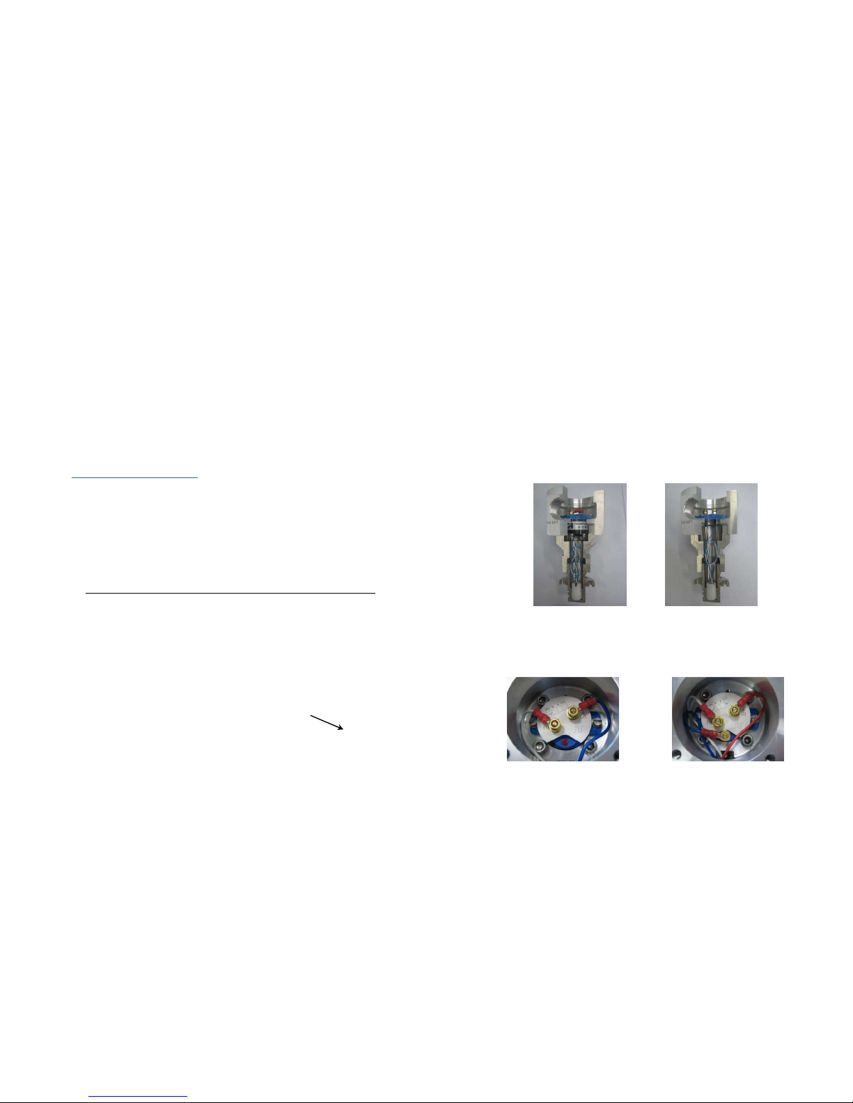
Electrical Installation
TZN turbine meters integrate two (or three) detection systems allowing generation of two out
of phase pulse trains. An integrated preamplifier FH71 (required for distance between meter and
control room greater than 600 ft) receives low level signals from the pick-up coil, and converts
these into positive square wave signals for long distance transmission (greater than 600 ft).
Preamplifiers are available in either a 2-wire (Intrinsically Safe versions) or -wire (non IS)
configuration.
Connection between the coil and preamplifier (or terminal) is completed in factory.
2 or wire preamp No preamp
Figure 8. Factory wiring of pickup coil: with and without preamp
Hazardous area classification must be checked prior to connection (refer to ATEX or UL plate).
Depending on preamplifier type (2 wire Standard, NAMUR or wire Open Collector); connect
the field shielded wire according to figures below.
2 wire preamp
(Standard / NAMUR)
wire preamp
(Open Collector)
Figure 9. Types of preamplifiers
Page 12 / 37
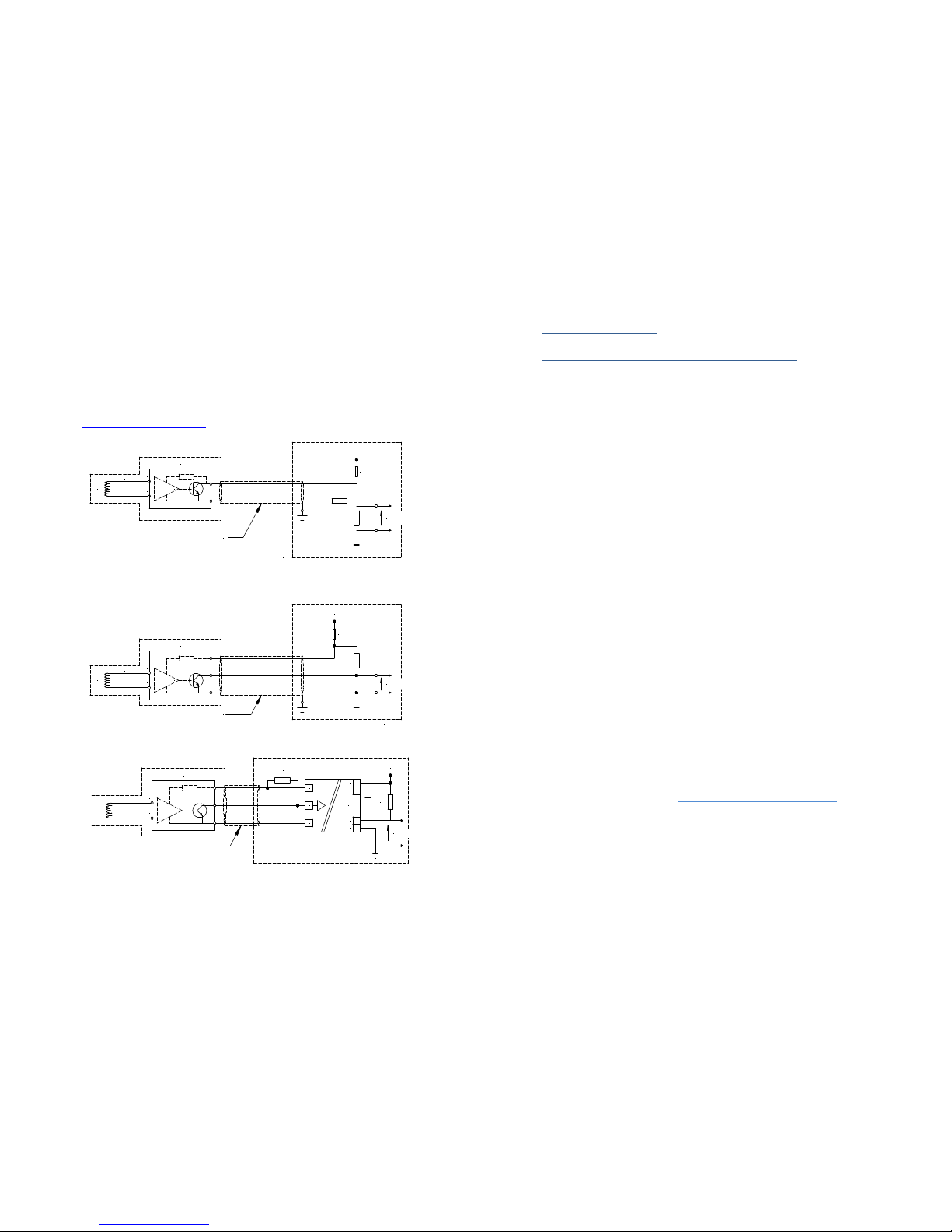
Wiring diagrams
Electrical connection to site (flow computer) depends on:
•
Protection type (Intrinsic Safety, Explosion Proof)
•
Flow Computer inputs characteristics (Impedance …)
•
Connection wire characteristics (resistance, inductance …) …
Wiring diagrams (below) can be used as ‘typical’. Additional configurations available on FH web site
(https://faureherman.zendesk.com).
2 wires FH71
A
B
Coil
2
1160
Ω
± 5%0.5W
470
Ω
± 5%
1 W
Ref Power Supply (0V)
Protection
fuse > 100 mA
24 VDC
Power Supply
AWG 16 shielded wire L < 500m (1,500 ft)
2.5 <VDT <10 V
(VDT: Voltage Detection Threshold)
white
blue
Figure 10
. Typical wiring diagram for 2 wires FH71with Input Impedance greater than 10 kΩ
3 wires FH71
A
B
Coil
3
1
white
blue
2
3.5 <VDT <20 V
Ref Power Supply (0V)
1.5k
Ω
± 5%
0.5W
Protection
fuse > 100 mA
5 to 28VDC
Power Supply
(VDT: Voltage DetetcionThreshold)
AWG 16 shielded wire L < 500 m(1,500 ft)
Figure 11. Typical wiring diagram for 3 wires FH71 (Open Collector)
0 < VDT < 12V
3 wires FH71
A
B
Coil
3
1
white
blue
2
AWG 16 shielded wire L < 500 m (1,500 ft)
1
k
Ω
± 5%
250 mW
4
5
1
14
13
11
12
+
-
+
-
+
-
MTL5532 0V
1 k
Ω
± 5%
1 W
Ref Power Supply (0V)
24 VDC
Power Supply
Figure 12. Example wiring diagram for 3 wires FH71 (Open Collector) with isolator
Page 29 / 37
Safety Consideration
Important Information Needed for Installation
This manual contains important instructions and safety information. It is essential to read and
understand the operating procedures prior to installation, connection, and commissioning of the
equipment.
Failure to observe these instructions and warnings may damage the flowmeter and/or
endanger personnel.
Personnel Requirements
Make sure that operators and maintenance personnel have all safety equipment applicable to
the area (safety glasses, protective headgear, safety shoes …) and are trained to operate the meter.
Unauthorized personnel should not have access to the operation of the meter.
Hazards arising from failure to o serve the instructions and warnings
Failure to observe these instructions and warnings may:
•
Expose personnel to mechanical, electrical, or chemical risk
•
Damage the equipment (meter)
•
Pollute the environment by releasing hazardous substances
Safety instructions
Power supply must be disconnected and flow meter must be depressurized before servicing to
avoid electrical and/or pressure hazards. The safety instructions in this manual, as well as all
accident prevention and occupational safety regulations in force in the country of installation, must
be observed.
Conditions of operation
Conditions of use indicated on the data plate must be observed; equipment reliability is
guaranteed only if it is installed and used as described in these manuals.
Installation and maintenance operation shall be done using the proper tools. Never use a
hammer or any tools which can create sparks or damage the equipment’s electrical protection
(enclosure, cable gland, conduit …). If impact wrenches are used, pay attention to torque
recommendations listed in TZN Manual.
Installation, maintenance and repair of the equipment shall be carried out by suitably trained
personnel; all spare parts shall be approved by Faure Herman. No operation or repair which can
affect the protective system can be done on this equipment without authorization by Faure
Herman.
For specific installation and maintenance advice, contact the Faure Herman Worldwide
Customer Support & Service via phone, email or website:
Hotline: +1 (71 ) 597 4827 (North America)
+ (0)2 4 60 28 55
Email: support@faureherman.zendesk.com
Online Assistance website: https://faureherman.zendesk.com/hc/en-us
Repair and maintenance
Repair, maintenance or potential modifications are allowed only after consultation with Faure
Herman. If any parts other than those approved by Faure Herman are used, Faure Herman cannot
be held liable for the consequences.
Transport, handling, and storage
The flowmeter must be handled with care to avoid damage. End caps are used to protect the
flanges during transport and handling.

Page 28 / 37
Appendix 3 - Operating restrictions & Special recommendations
The nominal operating process envelope is specified on the nameplate. This envelope is mainly
defined in terms of:
•
Minimum / Maximum – Flowrate
•
Maximum – Pressure
•
Minimum / Maximum – Temperature
Flowrate restrictions specify the equipment optimal performance envelope (measurement
accuracy and repeatability). The maximum value also sets the permissible continuous operating
limit. The maximum limit may occasionally exceed 120 % of the set value without negative impacts.
The pressure and temperature restrictions involve exclusively the equipment mechanical sizing
and define the authorized operating envelope.
Note: W en operating temperature is ig er t an t e indicated value, t e maximum aut orized
pressure s all be reduced, in strict application of t e ASME B16.5, NF EN 1759-1 or NF EN 1092-1
Standard.
Page 13 / 37
2 wires FH71
A
B
Coil
2
1
130
Ω
± 5% 0.25 W
510
Ω
± 1%
1W
Ref Power Supply (0V)
Protection
fuse > 100 mA
24VDC
Power Supply
AWG16shielded wire Lup to more than 1,000 m(3,000 ft)
white
blue
0V
(SPIRIT)
DIGITAL
INPUT(1)
Channels number 1 to 16: Select threshol 12V in Digital I/O settings
Figure 13. Typical 2 wires FH71 connection to SPIRIT Flow-X Flow Computer
3 wires FH71
A
B
Coil
3
1
white
blue
2
Ref Power Supply (0V)
1.2 k
Ω
± 5%
0.5W
Protection
fuse > 100 mA
12 to 24 VDC
Power Supply
AWG 16 shielded wire L < 500 m (1,500 ft)
Pulse +
Pulse -
S600 Pulse input
CH1 CH2 CH3 CH4
4 3 2 1
23 22 21 20
Pulse+
Pulse-
SKT-C
P148MezzanineCard:
Figure 14. Typical 3 wires FH71 connection to Emerson S600 FloBoss Flow Computer
2 wires FH71
A
B
Coil
2
1
620
Ω
± 51%
1W
Ref Power Supply (0V)
Protection
fuse > 100 mA
24VDC
Power Supply
AWG 16 shieldedwire L < 500 m (1,500 ft)
white
blue
0V
(OMNI)
PULSE
INPUT(1)
To be connected to terminal #5 or #6 on Type E Combo Module
Figure 15. Typical 2 wires FH71 connection to OMNI 3000/6000 Flow Computer
Chapter 5: Commissioning
After meter installation on pipe and completion of electrical connections, proceed with filling
of the pipe with liquid.
During initial filling of system, make sure any gas present in the pipe is purged by utilizing available venting
systems or by passing through the flowmeter at very low flow rate.
Avoid sudden filling of the flowmeter; this helps prevent formation of gas “pockets”, which can damage the
rotor and / or bearing system.
Avoid extended use of the flowmeter beyond the specified operating maximum flow rates.

Page 14 / 37
Chapter 6: Maintenance
The design of TZN flowmeter requires minimal maintenance when used within its operating
limits. A general recommendation is to replace the shaft and bearing assembly every three to five
years depending on process conditions such as continuous measurement, start and stop …
In the event of extended operational interruption, it is recommended to keep the flowmeter
full of liquid to keep the bearings from seizing, except when the liquid may crystallize or solidify.
Chapter 7: Trou leshooting
Problem Potential Cause(s)
Flowmeter overrates
1
–
2
–
5
-
7
–
8
–
9
–
10
–
11
Flowmeter underrates
1
–
2
–
-
4
–
5
–
6
–
8
–
9
–
10
–
11
Erratic indications
1
–
2
–
8
–
9
–
10
–
11
No signal 2 – – 4 – 6
Underlying Issue
Possible Solution(s)
1 Erratic pulses
Check cable shield and connection
Check for proper resistor selection (refer to wiring diagram)
Inspect pickup coil and/or preamplifier; replace if necessary.
2 Coil and/or preamp. defect
Check for proper wiring and resistor selection
Check for preamp type selection (N, S, CO)
Replace coil and/or preamp.
Loss of magnets
Replace the rotor
4 Damaged shaft or bearings
Replace bearing and/or shaft
Depending upon damage, possibly replace rotor and/or
crosspieces.
5
Damaged rotor
Replace
the rotor
6 Blocked rotor Inspect and clean bearing system, crosspieces and cartridge
Replace the cartridge if necessary
7 Deposits on internal walls
Clean all the cartridge components
Check installation conditions
Check/Inspect upstream elements such as strainer, flow
conditioner …
Replace the cartridge if appropriate
8 Flow profile deformation
Clean all the cartridge components
Check installation conditions
Check/Inspect upstream elements such as strainer, flow
conditioner …
Replace the cartridge if appropriate
9 Presence of gas in the flow
Eliminate the source of gas
Check installation conditions
Install a deaerator
10 Cavitation
Check installation conditions
Check/Inspect upstream elements (strainer, flow
conditioner)
Increase line pressure
11 Performances Recalibrate
Replace the cartridge if appropriate
Page 27 / 37
Appendix 2 - K-factor – Flowrate/Frequency
TZN Model Min Kfactor Linear Flow Range
Frequency
Range
mm -
m
/h
Inches -
BPH
p/m
(p/litre)
p/Bbl
(p/USG) m
/h BPH ~ Hz
16
–
012
0.5
–
0.
7
5
(5,200)
(19,700)
0.012
–
0.12
0.075
–
0.75
17
.
5
–
175
16
–
025
0.5
–
1.
5
(2,600)
(9,850)
0.025
–
0.25
0.157
–
1.57
18
–
180
20
–
05
0.75
–
.1
(1,600)
(6,060)
0.05
–
0.5
0. 14
–
.14
22
–
220
20
–
1
0.75
–
6.
(415)
(1,572)
0.1
–
1
0.6
–
6.
11
.
5
–
115
25
–
2
1
–
1
(125)
(47 )
0.2
–
2
1.
–
1
7
–
70
25
–
1
–
20
(125)
(47 )
0.
–
2
–
20
10.5
–
105
25
–
5
1
–
0
(125)
(47 )
0.5
–
5
–
0
17.5
–
175
25
–
10
1
–
6
(125)
(47 )
1
–
10
6.
–
6
5
–
50
2
–
8
1.25
–
50
( 8)
(145)
0.8
–
8
5
–
50
8.5
–
85
2
–
12
1.25
–
75
(29)
(110)
1.2
–
12
7.5
–
75
9.5
–
5
2
–
15
1.25
–
94
(18)
(68)
1.5
–
15
9.4
–
94
7.5
–
75
2
–
20
1.25
–
126
(18)
(68)
2
–
20
12.6
–
126
10
–
100
40
–
8
1.5
–
50
( 8)
(145)
0.8
–
8
5
–
50
8.5
–
85
40
–
12
1.5
–
75
(29)
(110)
1.2
–
12
7.5
–
75
9.5
–
95
40
–
15
1.5
–
94
(18)
(68)
1.5
–
15
9.4
–
94
7.5
–
75
40
–
20
1.5
–
126
(18)
(68)
2
–
20
12.6
–
126
10
–
100
40
–
40
1.5
–
250
(18)
(68)
4
–
40
25
–
250
20
–
200
50
–
0
2
–
190
(20)
(75)
–
0
19
–
190
16.5
–
165
50
–
50
2
–
20
(12)
(45)
5
–
50
2
–
20
16.5
–
165
50
–
70
2
–
440
(12)
(45)
7
–
70
44
–
440
2 .5
–
2 5
80
–
70
–
440
5,000
795
7
–
70
44
–
440
9.5
–
95
80
–
110
–
690
5,000
795
11
–
110
69
–
690
15
–
150
80
–
150
–
945
5,000
795
15
–
1
5
0
94.5
–
945
21
–
210
100
–
200
4
–
1,260
2,050
26
20
–
200
126
–
1,260
11.5
–
115
100
–
00
4
–
1,890
1,600
254
0
-
00
189
–
1,890
1 .5
–
1 5
150
–
400
6
–
2,520
900
14
40
–
400
252
–
2,520
10
–
100
150
–
600
6
–
,770
650
10
60
–
600
77
–
,770
11
–
110
200
–
800
8
–
5,0 0
80
60
80
–
800
50
–
5,0 0
8.5
–
85
200
–
1,000
8
–
6,290
80
60
100
–
1,000
629
–
6,290
10.5
–
105
200
–
1,200
8
–
7,550
80
60
120
–
1,200
755
–
7,550
12.5
–
125
250
–
1,200
10
–
7,550
150
2
120
–
1,200
755
–
7,550
5
–
50
250
–
2,000
10
–
12,600
150
2
200
–
2,000
1,26 12,600
8.5
–
85
00
–
2,400
12
–
15,100
90
1
240
–
2,400
1,510
–
15,100
6
–
60
00
–
,000
12
–
18,900
90
1
00
–
,000
1,890
–
18,900
7.5
–
75
50
–
,500
14
–
22,000
70
11
50
–
,500
2,200
–
22,000
7
–
70
400
–
4,000
16
–
25,200
50
8
400
–
4,000
2,520
–
25,200
5.5
–
55
400
–
4,500
16
–
28, 00
50
8
450
–
4,500
2,8 0
–
28, 00
6
–
60
450
–
4,800
18
–
0,200
40
6.5
480
–
4,800
,020
–
0,200
5.5
–
55
450 – 5,500 18 – 4,600 40 6.5 550 – 5,500 ,460– 4,600 6 – 60
500 – 6,000 20 – 7,800 0 5 600 – 6,000 ,780– 7,800 5 – 50

Page 26 / 37
Figure 31. Nominal Size CUS > 16''
1
Flanged body
4
Boss
2
Measurement cartridge
5
Enclosure adapter
2.1
Rotor
6
Enclosure
2.2
Shaft
7
Enclosure cover
2.
Upstream crosspiece
8
Coil
2.4
Central section
9
Preamplifier or Terminal
2.5 Downstream crosspiece
2.7
Bearing
2.10
Upstream thrust
2.11
Downstream thrust
2.12
Tightening set
Page 15 / 37
Chapter 8: Replacement – Repair
Preamplifier replacement
This operation is performed when the equipment is de-energized. Refer to magnetic sensors
manual:
•
Cut the sealing system (if any)
•
Unscrew the explosion-proof enclosure cover (4 screws)
•
Disconnect the pre-amplifier from the site wiring
•
Remove both fastening screws from the pre-amplifier in the enclosure
•
Remove the pre-amplifier from enclosure; take care to avoid stressing the coil
connection wiring
•
Disconnect the coil / pre-amplifier connection wiring
Figure 16.
Illustration of Preamplifier Replacement
•
Perform above in the reverse order to install the new pre-amplifier
•
Re-position and screw the enclosure cover. Reposition and tighten the screws to a 6 Nm
[
4.4 ft.lb
] torque.
•
Replace the sealing system (if required).

Page 16 / 37
Coil replacement
Metal Retaining Ring
This operation can only be performed after removal of the pre-amplifier (if present):
•
Disconnect the coil / pre-amplifier connection wire
•
Withdraw the coil while removing the retaining ring using specific tool (ref 870046)
•
Insert the new coil and retaining ring and push in place using the other part of the tool
kit
(ref 870046).
Figure 17. Illustration of Removal of Metal Ring type pickup coil
Engineered Polymer Retaining Ring
This operation can only be performed after removal of the pre-amplifier (if present):
Disconnect the coil / pre-amplifier connection wire
•
Insert tool (ref 870045) into the boss, taking care not to damage the wires, until the
adapter connects, and then unscrew the adapter.
•
Place the new coil in the polymer ring with wires coming through the top of ring
•
NOTE: Make sure the coil wires aren’t crimped when inserting the new coil into the base
of enclosure.
Page 25 / 37
Figure 30. Nominal Size STD > 16''
1
Flanged body
Retaining ring
2 Measurement cartridge 4 Boss
2.1
Rotor
5
Enclosure adapter
2.2
Shaft
6
Enclosure
2. Upstream crosspiece 7 Enclosure cover
2.4
Central section
8
Coil
2.5
Downstream crosspiece
9
Preamplifier or Terminal
2.6
Elastic ring
2.7 Fixed bearing
2.9
Bearing shaft

Page 24 / 37
Figure 29. Nominal Size CUS 4''-14''
1
Flanged body
4
Boss
2
Measurement cartridge
5
Enclosure adapter
2.1
Rotor
6
Enclosure
2.2
Shaft
7
Enclosure
cover
2.
Upstream crosspiece
8
Coil
2.4 Central section 9 Preamplifier or Terminal
2.5
Downstream crosspiece
2.7
Bearing
2.10
Upstream thrust
2.11 Downstream thrust
2.12
Tightening set
Page 17 / 37
•
Holding the coil wires, insert the ring in bottom of enclosure and screw into the base of
well, taking care to avoid crimping the wires or stripping the polymer threads, and then
remove the tool.
Figure 18. Illustration of Removal of Engineered Polymer Ring type pickup coil
Measurement cartridge replacement
For nominal size equal or lower than ", the cartridge is centered and fastened into the body
by means of an upstream stainless steel threaded ring.
Unscrew the inlet threaded ring and push the cartridge from the downstream direction to
remove it.
Figure 19. Cartridge replacement – meters <3’’
Note the direction of engraved arrow on the outer surface before inserting the cartridge into
the body and re-fitting and tightening the inlet ring. The cartridge upstream face must be on inlet
ring side.
For 4 to 14” nominal size, the cartridge is centred and fastened into the body by means of an
upstream stainless steel ring fixed with screws.
Remove the retaining screws from the inlet ring before pushing the cartridge out of the body.
Inlet Ring
Cartridge

Page 18 / 37
Figure 20. Cartridge replacement for meters 4’’ - 14’’
Note the direction of engraved arrow on the outer surface before inserting the cartridge into
the body and re-fitting and tightening the inlet ring. The cartridge upstream face must be on inlet
ring side.
IMPORTANT: For meters greater than 4”, it is strongly recommended to remove the cartridge
with the meter in a vertical position.
For meters equal or greater than 16", the cartridge is centered and fastened into the body by
means of an upstream and downstream stainless steel cross pieces integrating the cartridge parts.
Outer rings are fixed into the meter body to hold the cartridge in place with screws.
Figure 21. Cartridge replacement – meters >16’’
For STD bearing design, place the turbine in a vertical position with the upstream crosspiece
facing up, unscrew the screws holding the upstream crosspiece and remove the crosspiece.
Remove the rotor and the center part of the cartridge. Once all other components are removed,
turn the meter body over, remove the screws and the downstream crosspiece.
For CUS bearing design, place the entire turbine assembly in a vertical position with the
downstream face up, remove the brake pin and axle nut. Remove the center pieces. Unscrew the
screws holding the downstream crosspiece and remove the crosspiece. Remove the rotor and the
center part of the cartridge. Turn the turbine over before disassembling the upstream crosspiece.
Inlet Ring
Screws
Cartridge
Screws
Upstream Crosspiece
Rotor
Cartridge center part
Downstream Crosspiece
Downstream Crosspiece
Shaft
Page 23 / 37
1
Flanged body
Retaining ring
2
Measurement cartridge
4
Boss
2.1
Rotor
5
Enclosure adapter
2.2 Shaft 6 Enclosure
2.
Upstream crosspiece
7
Enclosure cover
2.4
Central section
8
Coil
2.5
Downstream crosspiece
9
Preamplifier or Terminal
2.6 Elastic ring
2.7
Fixed bearing
2.8
Adjustable bearing
2.9
Bearing shaft

Page 22 / 37
Figure 27. Nominal Size CUS ≤ 3''
1
Flanged body
4
Boss
2
Measurement cartridge
5
Enclosure adapter
2.1 Rotor 6 Enclosure
2.2
Shaft
7
Enclosure cover
2.
Upstream
crosspiece
8
Coil
2.4
Central section
9
Preamplifier or Terminal
2.5
Downstream crosspiece
2.7
Bearing
2.10
Upstream thrust
2.11
Downstream thrust
2.12
Tightening set
Figure 28. Nominal Size STD 4''-14''
Page 19 / 37
Figure 22. CUS Cartridge removal
Chapter 9: Equipment removal
The equipment is designed to operate under pressure and must be depressurized and drained
before removal (complete disassembly or removal of a component under pressure).
If the bolts must be loosened to drain liquid into a recovery tank, make sure the line is completely
depressurized prior to loosening bolts.
Axial nut &
Centering pieces
Rotor
Upstream Crosspiece
Cartridge center part
Page 20 / 37
Appendix 1 – Alternative configurations
Figure 23. TZN with local totalizer
Figure 24. TZN with thermal extensions
Figure 25. TZN with 3 pulse outputs
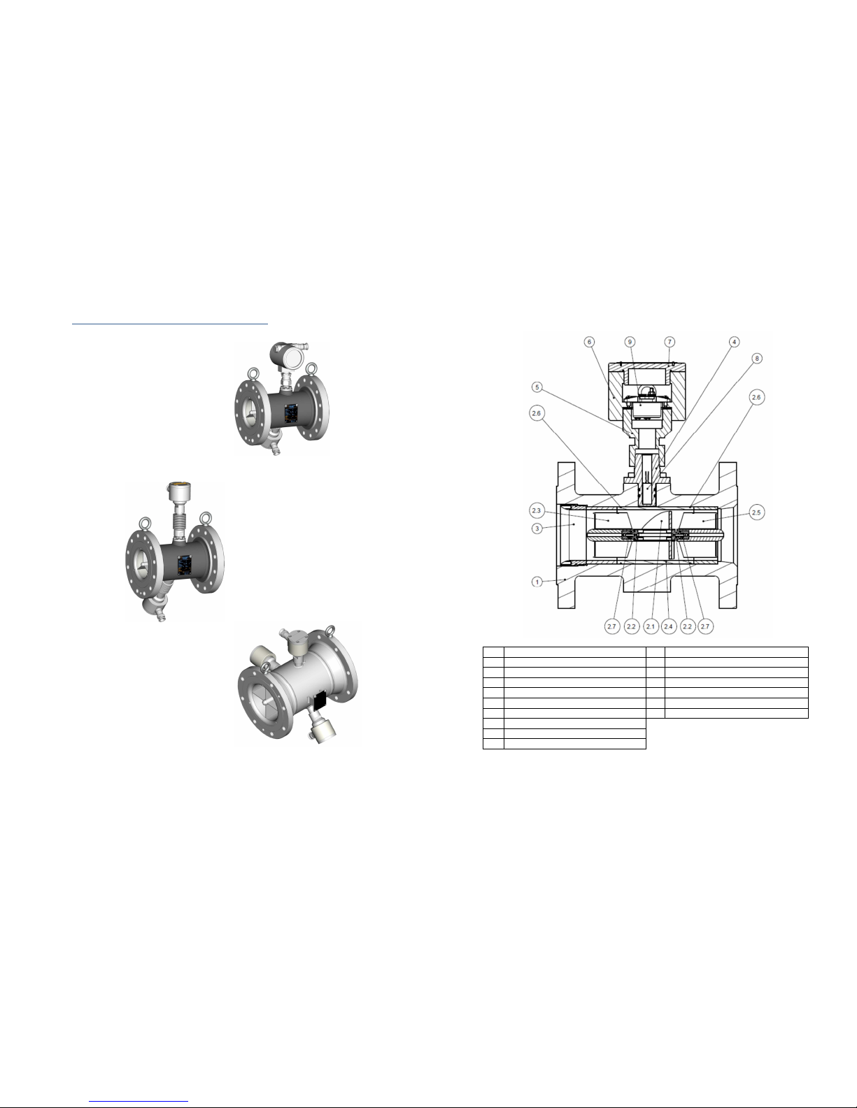
Page 21 / 37
Appendix 2 – Meter drawings y size and type
Figure 26. Nominal Size STD ≤ 3''
1
Flanged body
Retaining ring
2
Measurement cartridge
4
Boss
2.1
Rotor
5
Enclosure adapter
2.2
Shaft
6
Enclosure
2.
Upstream crosspiece
7
Enclosure cover
2.4
Central section
8
Coil
2.5
Downstream crosspiece
9
Preamplifier or Terminal
2.6
Elastic ring
2.7
Fixed bearing
2.9 Bearing shaft
Table of contents
Other FAURE HERMAN Measuring Instrument manuals


Popular Measuring Instrument manuals by other brands


PCB Piezotronics
PCB Piezotronics 482C27 General operations manual

Balluff
Balluff BNI IOL-802-000-Z036 user guide

Endress+Hauser
Endress+Hauser Tank Side Monitor NRF590 technical information

Long-run
Long-run LRF-3000S user manual

Impact Subsea
Impact Subsea ISFMD Installation & operation manual

Delta
Delta DVP08NTC-S instruction sheet


