FAURE HERMAN Ultraflux Minisonic II User manual

Instruction manual
Minisonic II
A trademark of
Ultraux
Ultrasonic flowmeters

Introduction
2 3
Contents
Introduction 2
Contents 3
Safety instructions 4
General characteristics 5
Wiring the Minisonic 8
Minisonic conguration 14
Installation and commissioning 28
Application example 34
Software update procedure 36
Logger / Retrieving recordings 38
Measuring signal gain adjustment mode 39
Thank you for choosing the Minisonic: we hope you will appreciate all its metro-logical
qualities
and ease of use.
The purpose of this manual is to guide you as simply as possible towards using the
instrument
condently to achieve results that match your expectations.
Specializing in ultrasonic ow meters since 1974, Ultraux develops, manufactures and
sells
solutions based on the principle of differential ultrasonic transit times.
This method provides non-intrusive, constant and bi-directional ow measurements.
Ultraux ow meters allow non-intrusive or intrusive, constant or occasional ow
measurements
on any type of homogeneous uid (liquid or gas) and through any type of homogeneous
material.
Always aiming to better serve its customers’ needs while preserving the environment,
Ultraux
has been committed for many years to a quality improvement and sustainable
development
policy.
Since it started in 1974, Ultraux has developed and manufactured all its products in France,
in
order to ensure that its production processes are reliable and meet the standard required.
ISO Certications
Ultraux is certied ISO 9001 and ISO 14001.
You can download the certicates : ISO9001– ISO14001
http://www.ultraux.net/downloads
Electrical Certications
Minisonic complies with the Low Voltage Directive (DBT) according to EN 61010-1
ATEX Certications
Some Ultraux products are also certied for use in ATEX hazardous areas.

General characteristics
Ultrasonic ow measurement by transit time measurement.
2 measuring cords (i.e. 4 probes)
Power supply: continuous 12-24Vdc or 110-220 Vac - Consumption: 7W typical, 15W peak.
Protection class: IP67 closed case
Dimensions / Weight
Width: 216mm / Height: 268mm / Depth (thickness): 90mm
Weight: 3.6 kg (with wall mounting plate)
Mechanics / Ergonomics
• Aluminum housing
• Wall mounting: special sheet metal rear panel + hole for locking screw accessible at the bottom of
the meter
• Monochrome graphic OLED display 128x64 pixels
• Lexan keyboard with 7 keys
• Blue LED: ultrasonic operation
• RGB LED for diagnostics (operation to be described according to the errors to be reported to the
user)
Cable glands
3x M20 type cable gland
Note: The M20 cable gland must be able to accommodate a reducer for the connection of two Pt100.
1x dedicated to the power supply
2x dedicated to In / Outputs and optional (module IN et module COM).
1x specically assigned to the ethernet cable
2x M25 type double cable gland : dedicated to probes connection (1x double cable gland per cord)
Integrated wiring compartment / integrated connection
Basic functions
Power supply : 3,5mm 3 ways connector (base plate with pluggable screw terminal block)
USB : vertical USB type A socket
Ethernet : horizontal RJ45 socket
In/Output (4/20mA and 2 ways Digital output) :
Connectors with 3.5mm pitch (base plates with spring-cage (pluggable) terminal blocks)
Probe connection: on stepped connector (socket strips with pluggable screw terminal blocks)
Optional function / Modules
Module « IN » : 4/20mA Input or Double Pt100 (2 or 3 wires)
Module « COM » : RS485 or RS232 with automatic detection by the device
Connectors with 3.5mm pitch (base plates with spring-cage (pluggable) terminal blocks)
Electrical characteristics Inputs / Outputs
Digital output: Maximum output voltage of 500V between contact and its ground
Current 1 mA at a frequency of 10 kHz
Modules In:
Galvanic insulation between modules: 500V
54
Safety instructions
Using the device
The device, equipped with ultrasonic probes, enables the ow measurement of a uid (gas or liquid) in a pipe.
It is important to set up the device correctly so that the measurement results are correct.
Your local Ultraux qualied contact is always available to assist with technical advice and on-site
assistance. This is strongly recommended if your equipment is used to control a process, to intervene in
a monitoring system, or in the case of other applications where incorrect ow measurement would entail risks.
Always ensure your Ultraux device is stored and operated according to the information in the technical
specication
The modication or disassembly of the unit must only be carried out by Ultraux personnel.
Always ensure the supply power is isolated before making connections to the equipment
Ultraux declines all responsibility for any incidents that may occur as a result of failure to observe these
instructions.
Equipments connected to the device
All equipment connected to the device must comply with the relevant safety standard and have SELV circuits.
(double insulation between primary and secondary)
Caution: The supply voltage of the measuring probes is high (may exceed 200V).
Maintenance work on the device
Maintenance of the device must only be carried out by Ultraux trained personnel and using only parts
supplied by Ultraux.
Temperature limits for Minisonic electronics
Use from -10°C to +40°C
Storage from -35°C to +60°C

Recycling the device
In accordance with decree no. 2005-829 of 20 July 2005 and decree no. 2009-1139 of 22 September
2009 concerning the obligations to collect, treat and dispose of electrical and electronic equipment,
batteries and accumulators in France, Ultraux delegates responsibility for the nancial and logistical
recovery to users who will manage their waste themselves. Separate collection and recycling of your
waste at the moment of disposal will help preserve natural resources and guarantee recycling
respectful of the environment and human health. For more information on the recycling centre nearest
to your site, contact your City Hall or waste disposal department.
CE marking
Ultraux Minisonic owmeters comply with CE certications.
Contact address
For any request for information, do not hesitate to contact us:
Postal address
Bâtiment Texas
9Allée Rosa Luxemburg
ÉragnyParc – Parc desBellevues
95610Éragny surOise
Delivery address
Bâtiment Texas
9Allée Rosa Luxemburg
ÉragnyParc – Parc desBellevues
95610Éragny surOise
After-sales
sav@ultraux.fr
+33(0)1 30 27 29 30
Email address contact@ultraux.fr
EN 55016-2-1 Conducted emissions measurements - criterion A
EN 55016-2-3 Radiated emissions measurements from 30MHz to 6GHz
EN 61000-4-6 Immunity to induced conducted disturbances - Criterion B
EN 61000-4-2 Immunity to electrostatic discharges - Criterion B
EN 61000-4-3 Immunity to radiated electromagnetic elds - Criterion A
EN 61000-4-4 Electrical Fast Transient / Burst Immunity - Criterion B
EN 610004-5 Surge immunity - Criterion B
IEC 60529 Degree of protection provided by the envelopes (IP)
76
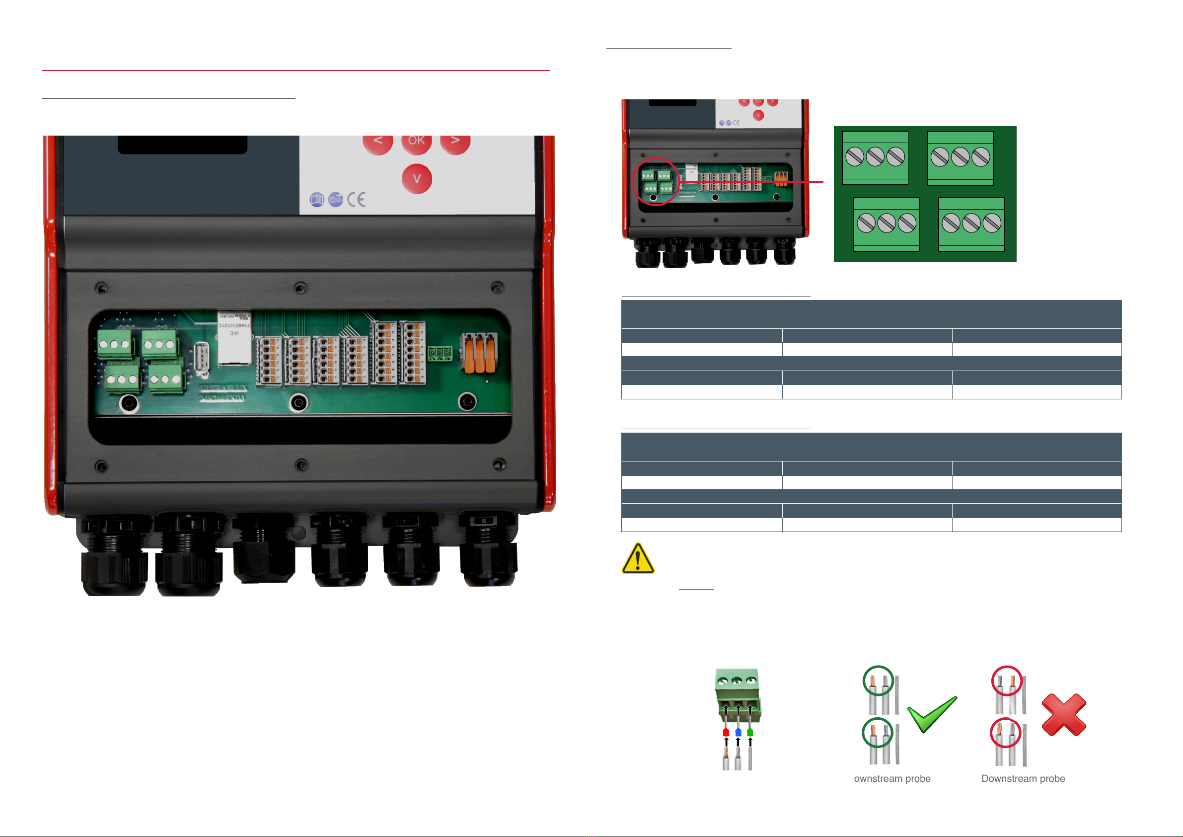
Probes connection
Connection of cord no. 1 (pair of sensors no. 1) and cord no. 2 (pair of sensors no. 2)
Note:
There is no + or - plug for connecting the sensors.
The choice of wire (silver or gold) for the upstream sensor must be the same for the downstream sensor
Example:
If the "gold" wire of the upstream sensor is connected to "upstream sensor +", then the "gold" wire of the
downstream sensor must be connected to "downstream sensor +" Caution: The supply voltage of the measuring
probes is high (may exceed 200V): Use electrical terminals
Upstream probe Upstream probe
Downstream probe Downstream probe
Fitting of electrical terminals recommended
Cord 1
Probe 1 / Upstream probe
PIN 1 PIN 2 PIN 3
Upstream probe + Upstream probe - Upstream probe ground
Probe 2 / Downstream probe
PIN 4 PIN 5 PIN 6
Downstream probe + Downstream probe - Downstream probe ground
Cord 2
Probe 1 / Upstream probe
PIN 1 PIN 2 PIN 3
Upstream probe + Upstream probe - Upstream probe
Probe 2 /Downstream probe
PIN 4 PIN 5 PIN 6
Downstream probe + Downstream probe - Downstream probe ground
Cord n° 1 - Pair of sensors n°1
Cord n° 2 - Pair of sensors n°2
Minisonic
Cord n° 1Cord n° 2
Probe 1
Probe 2Probe 4
Probe 3
123123
4 5 64 5 6
98
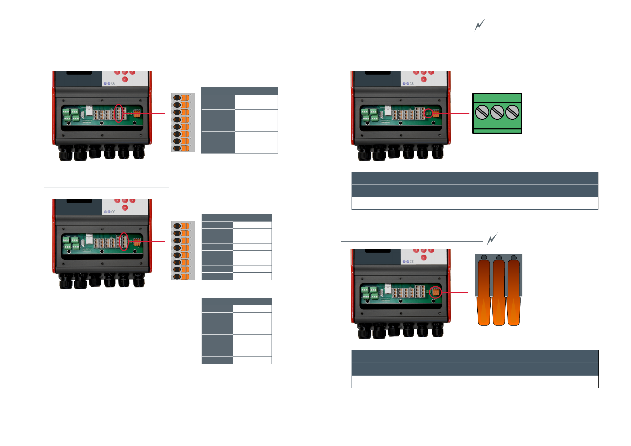
Wiring of the Minisonic
Overview of the connection compartment
Minisonic

Analogic 4-20 mA output
Connexion option
Digital output connection
Minisonic
PIN Function
1Contact 1 - A
2Contact 1 - B
3Contact 2 - A
4Contact 2 - B
5Contact 3 - A
6Contact 3 - B
Minisonic
PIN Function
124V
2S4-20 +
3S4-20 - (Ground)
4S4-20- (Ground)
5
6
Minisonic
PIN Function
1
2
3
4
5
6
1110
Minisonic
Minisonic
Minisonic
PIN Function
1RS485 A
2RS485 B
3Ground
4Ground
5RS232 TX
6RS 232 RX
Ethernet connection
USB socket
RJ 45 Ethernet socket
Through supplied specic cable gland
Connection of the serial link 232 - 485
1
2
4-20 mA active output
2
4
3
4-20 mA passive output
Powered by the loop
Or
USB Connection
Vertical USB type A socket for software update and logger download
DC Power supply connection DC 12-24 Vdc
AC Power supply connection 110 - 220 Vac
Minisonic
Minisonic
1 2 3
Power supply DC 12-24 Vdc
PIN 1 PIN 2 PIN 3
Ground 12-24 Vdc -12-24 Vdc +
Power supply alternating current 110 - 220 VAC
PIN 1 PIN 2 PIN 3
Ground Neutral Phase
123
1312
Minisonic
Current / Voltage input connection
Minisonic
Pt 100/1000 Temp. Probes connection
PIN Fonction
124V (IN1)
2IN1 +
3IN1 - (masse)
424V (IN2)
5IN2 +
6IN2 - (masse)
7IN V1
8IN V2
PIN Fonction
1Pt1 white
2
3Pt1 red
4Pt1 red
5Pt2 white
6
7Pt2 red
8Pt2 red
Connection 3 wires probe
PIN Fonction
1Pt1 white
2Pt1 red
3Pt2 white
4Pt2 red
5Pt3 white
6Pt3 red
7Pt4 white
8Pt4 red
Connection 2 wires probe

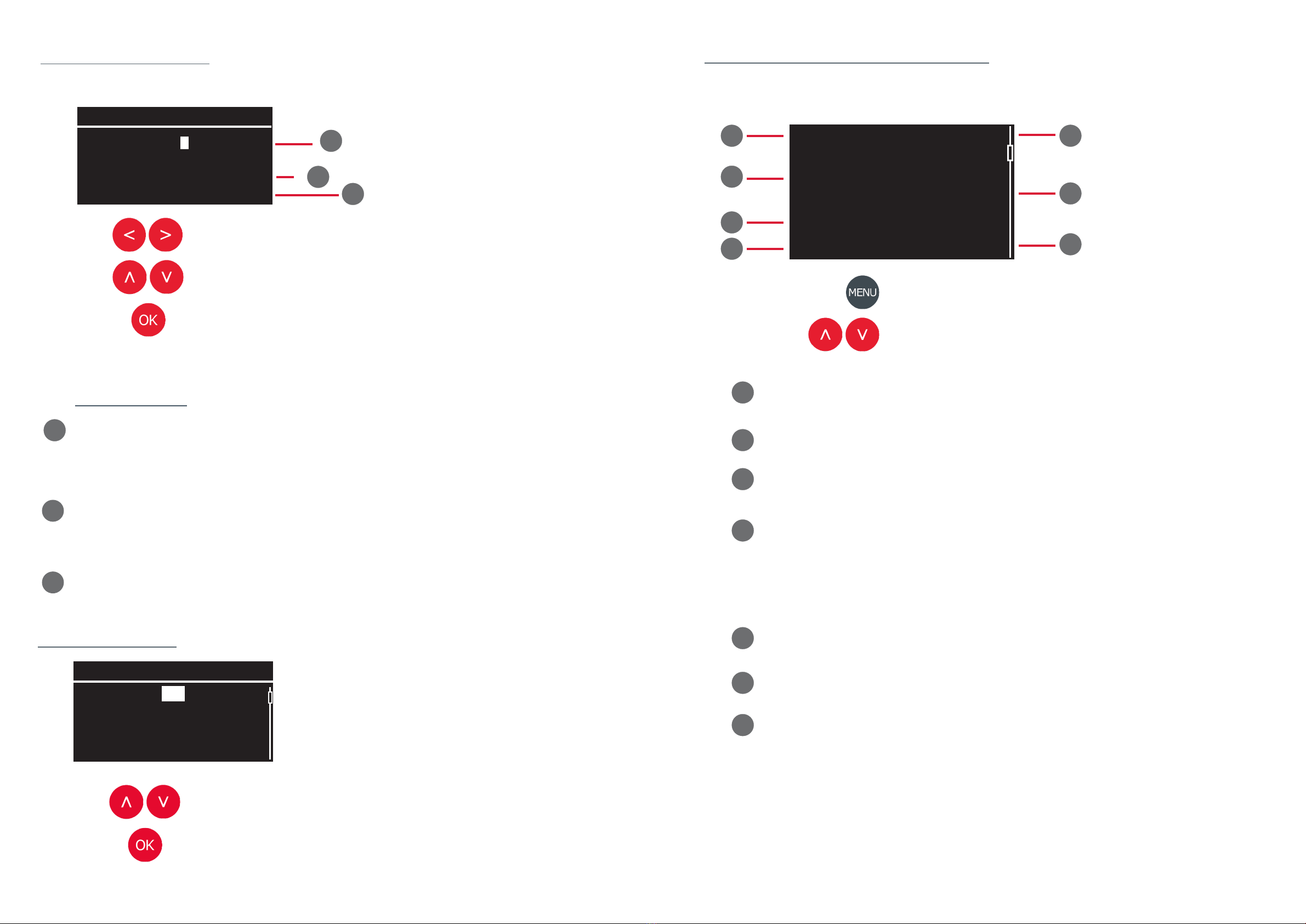
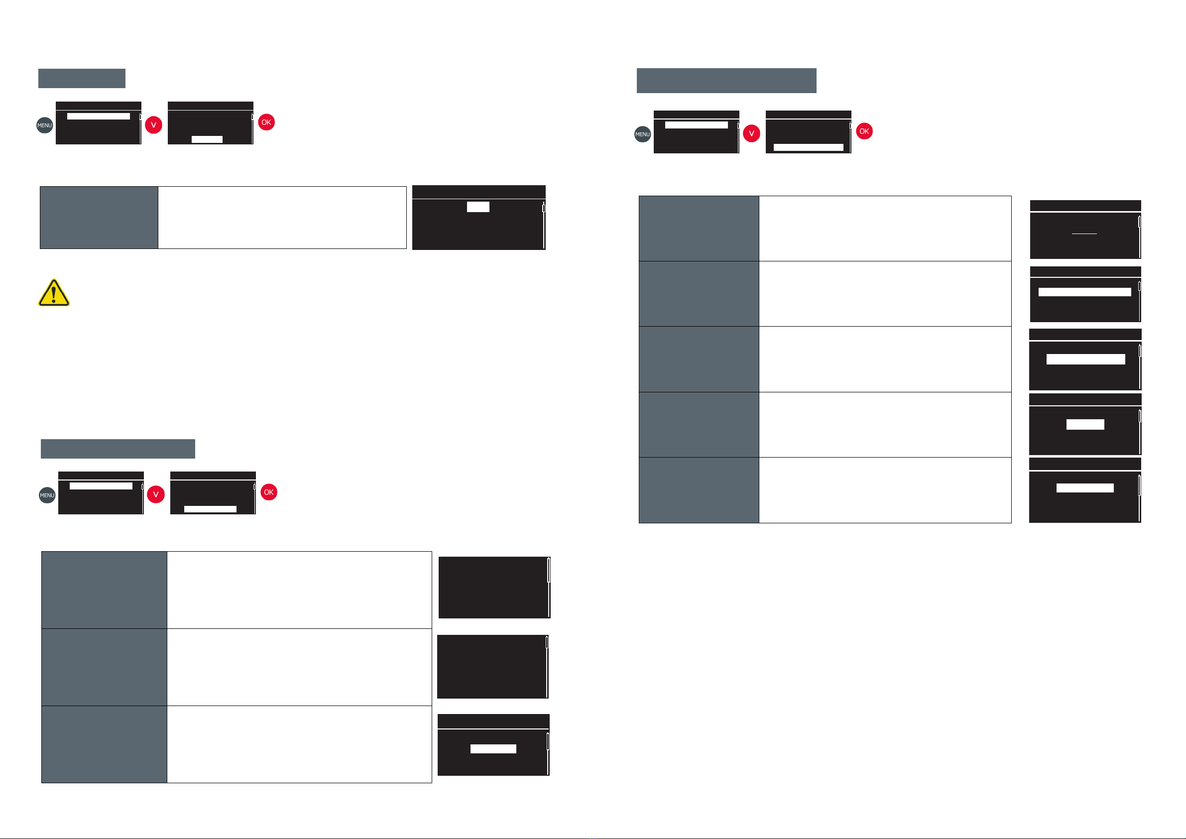
Minisonic conguration
The Minisonic is equipped with a screen and a keypad for conguration and viewing measurements directly.
Keypad
The keypad has seven keys which have different uses in different menus. However, navigation
between the elds and menus is always based on the same principles:
The menusdetailed in this manualcorrespond to the
Normal
modeof the setup level menu.
Switches between the measurementviewing
screens and the mainconfiguration menu
Takesyou back to the previous screen.
Changes measuringscreen, moves within the
menusor changes parameter values.
Goes into the menusin reverse video and is used
to validate the parametersselected.
Description of navigation
1514
LED Display
Flash indicating the emission of ultrasonic waves
Flash indicating measurement status
If on at least one pipe all chords are working: green ash
If at least one chord does not work, or if there is an error on the input/output: orange ash.
If at least one line does not have a measurement: red ash
1Fields currently being edited
Allows the eld being edited. Select a character using the multi-directional keys
and then select a character from the keypad to replace it.
2Select the characters to be placed in the eld by pressing "OK".
3"Delete" key : This key is used to delete the characters in the eld being edited.
"CapsLock" key switches from the keyboard with upper case keys to the keyboard with lower case keys.
"OK" key validates the eld and exits the screen.
2
13
4
5
Types of screen
The Minisonic Fixed is based on several types of screens which are found throughout the
navigation and work in the same way.
0 12 34 5 6 78 9 _ -
A B C D E F G H I J K L
M N O P Q R S T U V W X
YZ . ,
<-
Example 1.
cl
ok
These screens are used to edit all the alphanumeric elds of the device, such as driving name, conguration
names etc...
Figure 14 - Alphanumeric eld edit screen
<-
Example 1.
cl
ok
0 12 3 4 5 6 7 8 9 _ -
A B C D E F G H I J K L
M N O P Q R S T U V W X
Y Z .,
Screen for editing alphanumeric elds:
4
5
l/h
Display unit
l/d
m3/s
m3/h
l/h
List selection screen
Choice among the proposed list
Validates the modication and returns to the previous level
1716
Numeric eld edit screen
This type of screen allows entry all the numerical parameters in the device.
Currently edited eld :
The number being edited appears in black on a white background. The value of the eld is changed
using the up and down keys. Move from left to right using the direction keys to change the
number being edited.
Minimum eld value :
This number indicates the minimum value that can be set.
Maximum value of the eld :
This number indicates the maximum value that can be set.
Moving from digit to digit
Increases or decreases the value of the selected digit.
Validates the modication and returns to the previous level
Ext. Diameter
00022,20 mm
Min : 6,00 mm
Max : 10000,00mm 2
1
3
3
2
1
Presentation of the measurement screens
Main measurement variable
Example: Volume ow / Speed ...
Value of the main measurement unit
Designation of the secondary measurement variable
Example: Totalizer / speed / velocity / velocity / gain ...
Quality index
Indicates the percentage signal strength
This factor makes it possible to evaluate the difculty of measurement, for example it is lower
in the presence of loaded or aerated water. The higher the index, the simpler the
measurement is for the device to carry out.
Value of the secondary measurement variable
Physical unit of the main measurement variable
Physical unit of the secondary measurement variable
Access to menus
Views of the various measurement screens
Flowrate IQ100%
20,000m³/h
Totalizer
000000000026 m³
1
2
3
4
7
6
5
4
1
2
3
5
6
7

Parameter setting of the characteristics of line A and line B if multi-line.
Ext. Diameter
00048,30 mm
Min : 10,00 mm
Max : 10000,00mm
Ext. circumference
00069,12 mm
Min : 18,85 mm
Max : 31415,93mm
Thickness 1
003,20 mm
Min : 00,00 mm
Max : 500,00 mm
Material 1
PRV
PVC
PVC HP (rigid PVC)
PTFE
Roughness (RZ)
000,20 mm
Min : 00,00 mm
Max : 99,00 mm
l/h
Displayed unit
l/j
m3/s
m3/h
l/h
Pipe
Fluid
Water (Sea)
Water 05°C
Water 10 °C
Water 20°C
Setting the characteristics of the measured uid
Fluid
Menu
Measurement cong.
Probe distance
US Signal display
Auto zero
Measurement cong.
Measurement settings
Logger
Inputs / Outputs
Settings level
Pipe - A
Measurement settings
Pipe - B
Number of pipes
QT
Ext. diameter Adjustment of the outer diameter of the pipe.
Ext. circumference The outer circumference can be adjusted if the diameter is not measured.
Thickness Pipe thickness adjustment
In case of mufti-layer piping: 3 thicknesses can be set in the EXPERT setting mode
Material
Choice of driving material from a list.
In the case of multi-layer piping: possibility of setting 3 materials in EXPERT setting
mode
Roughness Specic roughness the inner wall of the pipe
Displayed unit Choice of volume ow unit
Determines the physical unit associated with the volume ow rate display.
Example: m3 /h - l/min...
Note: The choice of uid will be differentiated between Pipe A and Pipe B if Multi-pipe.
Fluid Choice of the uid to be measured from a list
Pipe
Pipe - A
Fluid
Pairs of probes
Filtring
Ext. Diameter
73.00 mm
1918
Pipe - A
Menu
Measurement cong.
Probe distance
US Signal display
Auto zero
Measurement cong.
Measurement settings
Logger
Inputs / Outputs
Settings level
Pipe - A
Measurement settings
Pipe - B
Number of pipes
QT
Pipe
Pipe - A
Fluid
Pairs of probes
Filtring
Fluid
Acetone
Fluid - A
Note: The setting sub-menu for line A is the same for line B if the multi-line option is selected.
Menu
Measurement config.
Probe Distance
US Signal display
Auto zero
Conguration menus
Choice of chapter
Conrms the entry in the chapter in "inverse video" display.
Back to the previous chapter
Back to the measurement screen
Measurement conguration
Conguration of the set of characteristics of a measuring point.
In this menu, you will set up the device to operate on a specic application: Pipe characteristics / Fluid
characteristics / Characteristics of the used probes
Probe distance States the distance to be set between the sensors according to the data set in "Measurement
Conguration"
US signal display
Displays the nature and quality of the measurement echo. It is a key factor in the analysis of
the measurement conditions and can help you to identify any conguration error (diameter - thickness of
the pipe ...).
Auto-Zero
Gives you the possibility to rene the response of the unit under the strict conditions of "Full pipe + Flow
at standstill".
This operation is essential to obtain optimal uncertainty
Advanced meas. Gives you access to additional diagnostic information
System Conguration Setting the language information / Date Time / Custom features

Setting of the probes used with the device
Pairs of probes
Note :
The parameter setting of the probes is the same for probe pair 1 and probe pair 2 in the case of
multi-cords.
If the "number of pipes" is set to "2", each pipe has only one sensor pair. If only one line is
congured, it has the option of using 2 pairs of sensors.
Filtering - A
Memory
5 s
Filtering - A
Flowrate cut off
100,000 l/s
Measurement ltering settings
Damping
Damping time of the measurement.
Setting to be made in the sub-menu for editing a numeric eld (Unit in
seconds)
Memory
Maintain measurement in case of signal loss.
Setting to be made in the sub-menu for editing a numeric eld (Unit in
seconds)
Flowrate cut off
Flow threshold below which the measurement is forced to zero.
(Display and outputs)
Setting to be made in the editing sub-menu of a numeric eld
(Threshold value and unit).
Setting the totalizer
Activate
Yes
Totalizer - A
Mode
+
Totalizer - A
Weight
1 m³
Totalizer - A
Reset Totalizer
No
Totalizer - A
Activate Activates the totalizer of line A
Mode Mode selection: "Forward ow + " " Reverse ow - " " Net +/- " ".
Weight Adjusting the totalizer increment weight
Reset Totalizer Zeroing the totalizer
Entrées / Sorties
Enregistreur
Mode basse conso.
2120
Entrées / Sorties
Enregistreur
Mode basse conso.
Setting the number of pipes
Conguration Mesure / Paramétrage mesure/ Nombre de conduites
Numbers of pipes
The Minisonic is a owmeter that can manage ow measurement on 2 different
pipes.
Minisonic has the capacity to drive 2 pairs of probes:
• 2 different pipes with 1x pair of sensors each
• 1 Pipe with the possibility of using 2 pairs of sensors on it
Number of pipes
2
Min: 1
Max: 2
QT Setting
Conguration Mesure / Paramétrage mesure/ QT
QT
• QT is the mathematical operation carried out with the 2 possible
measurements on the Minisonic:
Either an addition of the 2 measurements / A difference ....
• The unit of display of this total ow rate is congurable.
• In the event of a measurement failure, it is possible to signal a loss of signal
either with only one channel faulty or with both channels faulty
simultaneously.
Note: The setting sub-menu for line A is the same for line B if the multi-line option is selected.
Menu
Measurement cong.
Probe distance
US Signal display
Auto zero
Measurement cong.
Measurement settings
Logger
Inputs / Outputs
Settings level
Pipe - A
Measurement settings
Pipe - B
Number of pipes
QT
Pipe
Pipe - A
Fluid
Pairs of probes
Filtering
Probes
SE 1790
Pair of probes
Filtering
Menu
Measurement cong.
Probe distance
US Signal display
Auto zero
Measurement cong.
Measurement settings
Logger
Inputs / Outputs
Settings level
Pipe - A
Measurement settings
Pipe - B
Number of pipes
QT
Pipe
Pipe - A
Fluid
Pairs of probes
Filtring
Damping
0 s
Filtering - A
Filtering - A
Damping
5 s
Totalizer
Menu
Measurement cong.
Probe distance
US Signal display
Auto zero
Measurement cong.
Measurement settings
Logger
Inputs / Outputs
Settings level
Pipe - A
Measurement settings
Pipe - B
Number of pipes
QT
Pipe - A
Fluid
Pairs of probes
Filtering
Totalizer
Activate
No
Totalizer - A
Menu
Measurement cong.
Probe distance
US Signal display
Auto zero
Measurement cong.
Measurement settings
Logger
Inputs / Outputs
Settings level
Measurement settings
Pipe - A
Pipe - B
Number of pipes
QT
Number of pipes
Menu
Measurement cong.
Probe distance
US Signal display
Auto zero
Measurement cong.
Measurement settings
Logger
Inputs / Outputs
Settings level
Measurement settings
Pipe - A
Pipe - B
Number of pipes
QT
QT
Pipe A
+
QT
Pipe B
+
QT
Dispalyed unit
m³/h
Faults
All Q fault
QT
QT
Pair of probes
SE 1662-10
SE 1515
SE 1815
SE 1790
Ultrasonic path
Direct (/)
1 reection (V)
2 reections(N)
3 reections(W)
Delta T Zéro
+00,50 ns
Min : -300,00ns
Max : 300,00ns
Probes Choice of probe model from a scrolling list
Mounting type Choice of probe mounting type
ZERO Difference in transit time of the sound wave at zero ow.
Value set automatically after "Auto Zero".
Gain mode See appendix / Description of the gain adjustment on page 30
Time offset
Pair of probes
Gain mode
ESC
Pair of probes
Time offset
0,00 µs

2322
Setting Inputs / outputs
Current ouput 1
Contact output 1
Function selection: Counting / Alarm / Test On / Off
Counting :
Choice of ow variable (A / B / A+B pipe)
Counting direction (Direct + / Reverse - / Net )
Pulse length
Pulse weight (value and unit)
Alarm :
Choice of the variable linked to the alarm
Contact output 2
Function selection: Counting / Alarm / Test On / Off
Counting :
Choice of ow variable (A / B / A+B pipe)
Counting direction (Direct + / Reverse - / Net )
Pulse length
Pulse weight (value and unit)
Alarm :
Choice of the variable linked to the alarm
PT100 input (1-2-3-4)
Setting the characteristics of the Pt 100 input
• Number of wires
• Setting the temperature oset
Tests Test mode of the analogue and contact outputs
Caution: in test mode, the output values will be changed.
Conguration of the internal recorder
Logger
File name
Test
File name Dene the name of the recording le associated with the measurement
point.
Number of data Setting the number of variables to be recorded
Period Choose a sampling period from a scrolling list
Data 1..2..3..
Dene the nature of each variables
Pipe: Physical quantities (Flow, Speed, Speed...)
General: Device status, battery charge status
Type
Choose the type of value applied to all data
• Average
• Average + Min + Max
• Average + Min + Max + Standard deviation
Menu
Measurement cong.
Probe distance
US Signal display
Auto zero
Measurement cong.
Measurement settings
Logger
Inputs / Outputs
Settings level
Logger
Settings
File management
Logger
Logger
Number of data
3
Logger
Period
10 s
Logger
Data 1
Pipe - A
Flow
Logger
Type
AVG, Min, Max
Menu
Measurement cong.
Probe distance
US Signal display
Auto zero
Measurement cong.
Measurement settings
Logger
Inputs / Outputs
Settings level
Inputs / Outputs
Current output 1
Contact output 1
Contact output 2
PT100 input 1
Inputs / Outputs
Inputs / Outputs
Inputs / Outputs
Inputs / Outputs
Inputs / Outputs
Inputs / Outputs
PT100 input 2
PT100 input 3
PT100 input 4
Tests
Current output 1
Contact output 1
Contact output 2
PT100 input 1
Current output 1
Contact output 1
Contact output 2
PT100 input 1
Current output 1
Contact output 1
Contact output 2
PT100 input 1
Current output 1
Contact output 1
Contact output 2
PT100 input 1
Adjustment of the characteristics of the 4-20 mA analogue output
Activation / deactivation /
• Selection of the variable to be assigned to this output
• Flow rate corresponding to 4 mA
• Flow rate corresponding to 20 mA
• Flow rate unit
• Default value in case of fault (in mA)
Display of the probe spacing distance
Measurement cong. / Probe distance
Probe distance
Pair of probe 1 - A
54.4 mm
Pair of probe 1 - B
48.6 mm
Menu
Measurement config.
Probe distance
US Signaldisplay
Auto Zero
Menu
Measurement config.
Probe distance
US Signaldisplay
Auto Zero
Probe distance
Displays the distance between the sensors.
This distance is calculated by the device according to the congured
parameters:
• Diameter / thickness / pipe material
• Type of uid
• Type of probes
The example on the right shows the distance to apply between the
probes of the Pipe A and Pipe B
Visualisation of measurement echoes
Measurement cong. / US signal display
79.7µs
13 dB
13dB AB
0.5 ns
13dB BA
0.5 ns
13dB ABBA
79.3 ns
Allows the viewing window to be moved for signal assessment
Allows the display to be centred on the measuring point.
Large view Wide visualisation of the quality of the measurement signal according
to the programmed parameters and measurement conditions
Echo from A to B
Visualisation of the ultrasonic echo emitted from probe A and
received on probe B
Echo from B to A
Visualisation of the ultrasonic echo emitted from probe B and
received on probe A
Phase shift AB-BA Visualisation of the 2 echoes and the difference in transit time of the
ultrasonic wave between the AB and BA paths
2524
Settings level
Simple
Normal
Advanced
Simple
Normal
Advanced
The Minisonic has been designed to adapt to your level of knowledge of ultrasonic measurement.
The menus detailed in this manual correspond to the Normal mode of the setting level menu.
Settings level
Simple Contains the minimum parameters necessary to do ow measurement
with the minimum of parameters to be set
Normal Gives access to more features and settings to rene the measurement
Advanced Contains all the parameters available in the unit. Simple
Normal
Advanced
Reset cong.
Deletes the data in the current conguration and returns to the
default conguration.
A warning message will pop-up on the screen to ask for reset
conrmation
Save cong.
Saves the current conguration
Ask a name for this conguration so that you can use it again latter
Load cong. Uploads the parameter data of a saved conguration
Delete cong. Deletes selected or all conguration les
Conguration management
Menu
Measurement cong.
Probe distance
US Signal display
Auto zero
Measurement cong.
Measurement settings
Logger
Inputs / Outputs
Settings level
Settings level
Menu
Measurement cong.
Probe distance
US Signal display
Auto zero
Measurement cong.
Logger
Inputs / Outputs
Settings level
Cong. Management
Config. Management
Config Management
Reset config.
Save config.
Load config.
Delete config.
Config Management
Reset config.
Save config.
Load config.
Delete config.
Config Management
Reset config.
Save config.
Load config.
Delete config.
Config Management
Reset config.
Save config.
Load config.
Delete config.
Settings level
Settings level
Menu
Measurement config.
Probe distance
US signal display
Auto Zero
Menu
Measurement config.
Probe distance
US signal display
Auto Zero
(....)
Setting the device system data
System conguration
Main
Langue
English
Custom data
Custom probes
Custom uids
Custom materials
Communications
Serial conguration
IP network
Informations
Firmware
Hardware
Serial number
Date and Time
Date format
Date
Time
Main
Denition of :
• Display and programming language
• Distance units mm or inches
Custom data
The Minisonic allows the customised setting of:
• Probes
• Fluids
• Pipe materials
Communication • Serial communication setting
• IP Setting
Information
Display of:
• Software version (Firmware)
• Electronic board version (Hardware)
• Serial number of the device
Date et heure
Adjustment and adjustment of:
• Format DD/MM/YY ...
• Date
• Time
2726
Minisonic zero ow adjustment
Auto Zero
30s
Auto Zéro
Caution, this operation can only be carried out under the strict conditions of:
• Full pipework
• Zero ow
This operation is essential in order to obtain optimal accuracy. The actual stabilisation of the uid ow
at zero ow can take + or - time. This stabilisation depends on the diameter of the pipe and the type of
shut-off devices. Make sure that the ow is actually mechanically shut off (valve....).
Auto Zero Determines the duration of zero point adjustment.
Visualisation of diagnostic variables and failures
Advanced meas.
4 Faults
Flowrate - A
Velocity - A
Flowrate - B
Velocity - B
Pipe -A
Flowrate 124.30
m³/h
Velocity 1.25 m/s
S. Of sound 1482 m/s
IQ 100 %
Faults Total list of faults found by the device.
Flowrates View of advanced variables allowing adjustment, reliability
or validation of measurement quality.
IP network Network
Menu
Measurement cong.
Probe distance
US Signal display
Auto zero
Menu
Measurement cong.
Probe distance
US Signal display
Auto zero
Menu
Measurement cong.
Probe distance
US Signal display
Auto zero
Menu
Probe distance
US Signal display
Auto zero
Advanced meas.
IP network
IP network
Network faults
Menu
Measurement cong.
Probe distance
US Signal display
Auto zero
Menu
US Signal display
Auto zero
Advanced meas.
System conguration

Installation and Commissioning
Setting up a measuring point
Your local Ultraux trained representative will be happy to provide advice on site selection and
provide other technical assistance installing the owmeter
In addition to the control unit, either or external or insertion probes will be requiered
External sensors
A pair of potted cable probes with the required cable length
Suitable mounting brackets and xing systems
Insertion probes
A pair of intrusive probes equipped with their mounting system (e.g. Valve / Boss...).
The required cable length between the sensors and the electronics.
Choosing a location for the probes
The following sets out the main precautions to be taken when choosing a location for the probes.
To achieve the most accurate measurement possible, it is necessary to have what is called ‘a developed
ow prole’. The aim is to obtain a hydraulic prole which is as predictable and symmetrical as possible.
Choosing the measurement mode
The external sensors can be installed in different ways, depending on the number of reections of the
ultrasonic wave on the pipe wall. There are four programmable types in the device:
Figure 12-Profil hydraulique asymétrique
2928
Figure 10a- Symmetrical hydraulic prole Figure 10b- Asymmetrical hydraulic prole
«Direct» or«/» «Reflex» or«V»
«N» «W»
The preferred mounting method is the V-shaped mounting, which is suitable in most cases.
The longer the distance, the better the measuring principle is exploited. (signicant difference in travel time
upstream and downstream).
However, the ultrasonic echo will be all the weaker and more distorted as the number of reections
increases and may be difcult to process. A compromise must therefore be found between precision and ease
of transmitting and receiving ultrasound. This compromise depends on the application (uid, wall quality, diameter,
etc...).
In practice, multiple reection modes are reserved for smooth pipes without fouling or corrosion.
Probe positioning
The measuring probes must be placed in such a way as to avoid areas at risk of air bubbles and sediment.

Measuring near an elbow
Reex mode V : Distance > (3x) pipe diameter
Direct mode / : Distance > (5x) pipe diameter
Reex mode V : Distance > (15x) pipe diameter
Direct mode / : Distance > (20x) pipe diameter
Reex mode V : Distance > (15x) pipe diameter
Direct mode / : Distance > (20x) pipe diameter
Reex mode V : Distance > (3x) pipe diameter
Direct mode / : Distance > (5x) pipe diameter
Reex mode V : Distance > (15x) pipe diameter
Direct mode / : Distance > (20x) pipe diameter
Respect for straight pipe lengths
We know the rules to be followed according to the layout of the pipes to obtain the ideal measuring
conditions. The following paragraphs provide information on the general rules to be observed.
For liquids, the following instructions show the minimum distances (L) before and after a
disturbance as a function of the inside diameter of the pipe (D) so that the errors induced by these
disturbances remain below ± 1 %.
Measuring close to a valve
Measuring close to a divergent
Measuring close to a convergent
Reex mode V : Distance > (15x) pipe diameter
Direct mode / : Distance > (20x) pipe diameter
Reex mode V : Distance > (5x) pipe diameter
Direct mode / : Distance > (8x) pipe diameter
Reex mode V : Distance > (30x) pipe diameter
Direct mode / : Distance > (40x) pipe diameter
Reex mode V : Distance > (3x) pipe diameter
Direct mode / : Distance > (5x) pipe diameter
Reex mode V : Distance > (10x) pipe diameter
Direct mode / : Distance > (15x) pipe diameter
Reex mode V : Distance > (3x) pipe diameter
Direct mode / : Distance > (5x) pipe diameter
3130

Recommended locations:
Pipework with ascending ow.
Choice of probe type
The choice of the sensor pair depends on the pipe diameter.
The frequency of the probe has an important effect on the quality of the measurement.
The Minisonic can be used with many probes that are suitable for different pipe diameter ranges.
The following table denes the average operating ranges of the probes according to their frequencies:
Note: The values given in the table correspond to the internal diameter of the pipe (or nominal).
Frequency Pipe diameter
2 MHz 10 - 400 mm
1 MHz 40 - 2 500 mm
500 kHz 100 - 10 000 mm
Installation of the Clamp-on probes
Installation of the elastomer strip
It can be used for any surface temperature between -30°C and +100°C.
Grease the line with grease where
the probes are located (Do not
use silicone grease).
Découper un morceau dʼélastomère
de la dimension de la sonde +5mm
Enlever le lm protecteur
Cut a piece of elastomer the size
of the probe +5mm.
Remove the protective lm
Apply grease to the outside of the
elastomer strip.
Place the sensor and its holder and secure them by tightening the stainless steel
clamps.
Place the clamping screws of the clamps preferably opposite the probes.
NB: The observation of the evolution of the gain (dB) measured by the owmeter can
allow to identify the degradation of the coupling and to foresee its replacement.
Pipe preparation
Installation of one of the probes
After determining where the sensors are to be
installed, clean the pipe surface by removing
dirt, rust and any roughness (paintwork is not
a problem if it is in good condition).
3332
Comments :
The values indicated must be multiplied by 2.5 for gases.
Convergent pipework with an overall angle of less than 16° are not taken into account and are considered as
straight lengths (this is not the case for divergent pipework).
Locations not suitable:
Vertical pipe with downow, especially in the case of free ow
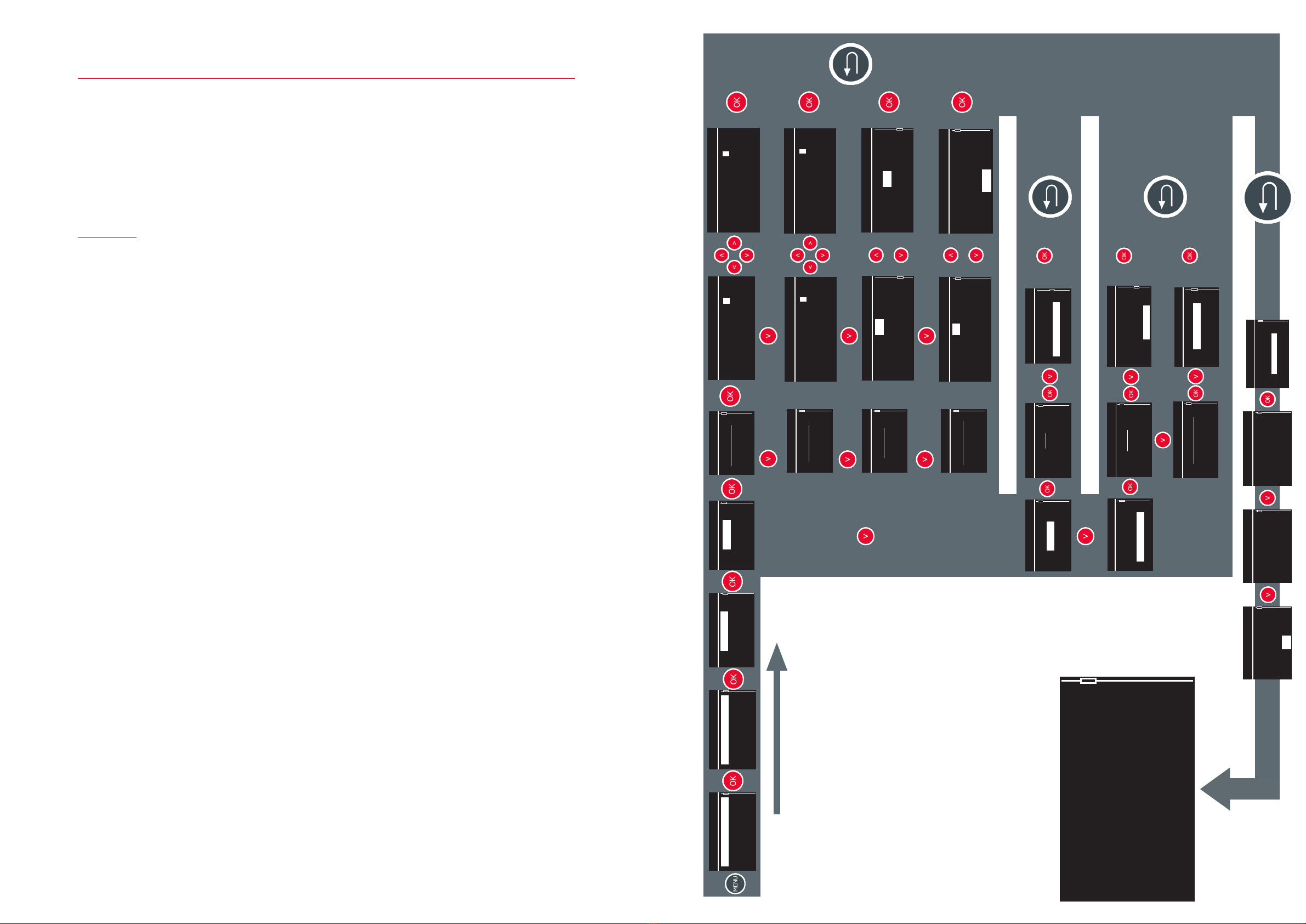
Application example
Flow measurement with an ultrasonic owmeter requires the following information:
• Pipe characteristics (External diameter + Thickness + Material)
• Fluid characteristics
• Probes used (Model)
Application
• PVC pipe / Outer diameter 48.3mm / Thickness 3.2mm
• Fluid measured: Fresh water at 12°C.
• Probes used: SE 1790, V-mounting
Use the overview on the next page to congure the unit according to the data in the example.
34
(...)
Menu
Measurement cong.
Probe distance
US Signal display
Auto zero
Measurement cong.
Measurement settings
Logger
Inputs / Outputs
Settings level
Pipe - A
Measurement settings
Pipe - B
Number of pipes
QT
Pipe
Pipe - A
Fluid
Pairs of probes
Filtring
Ext. Diameter
73.00 mm
Pipe - A
Thickness 1
1.50 mm
(...)
Pipe - A
Material 1
PRV
Pipe - A
Pipe
Pipe - A
Fluid
Pairs of probes
Filtring
Fluid
Acetone
(...)
(...)
Fluid - A
Pipe
Pipe - A
Fluid
Pairs of probes
Filtring
Probes
SE 1815
Pair of probes 1 - A
Ultrasonic path
Direct (/)
Pair of probes 1 - A
Pair of probes 1 - A
SE 1662-10
SE 1515
SE 1815
SE 1790
Fluid
Water (Sea)
Water 05°C
Water 10 °C
Water 20°C
Ext. Diameter
00073,00 mm
Min : 10,00 mm
Max : 10000,00mm
Thickness 1
001,50 mm
Min : 00,00 mm
Max : 500,00 mm
Material 1
PRV
PVC
PVC HP (rigid PVC)
PTFE
l/h
Displayed unit
l/j
m3/s
m3/h
l/h
Ext. Diameter
00048,30 mm
Min : 10,00 mm
Max : 10000,00mm
Thickness 1
003,20 mm
Min : 00,00 mm
Max : 500,00 mm
Material 1
PRV
PVC
PVC HP (rigid PVC)
PTFE
l/h
Displayed unit
l/h
l/d
m3/s
m3/h
Ultrasonic path
Direct (/)
1 reflexion (V)
2 reflexions (N)
3 reflexions (W)
Displayed unit
l/h
Pipe - A
Setup validation
5 datas have been
modied :
Use modications
Discard modications
Probe distance
Pair of probe 1 - A
54.4 mm
Pair of probe 1 - B
48.6 mm
Probe distance
Validate this screen
only after having
Positioned the probes
Correctly so that the
Probe distance
Measurement starts
under good conditions
Thank you
OK
Flowrate IQ100%
20,000m³/h
Totalizer
000000000026 m³

Software update procedure
In order to reach the specic area for system modication and software update you must:
• Save the update le on the root of a USB key.
• If there are several update les, the unit will ask you to leave only one.
• Connect the USB key to the unit's USB port.
• Switch on the Minisonic with the USB cable and the key connected to the unit.
System Menu
Update
Informations
Battery
Battery indicator reinit.
ULTRAFLUX
MINISONIC
54R 3RO 2ROL
•During the ignition phase which lasts 3 seconds
Successively press and release then
• A countdown timer appears in the upper right-hand corner for 5 seconds.
• Enter the password before the countdown reaches 0 : ROL (Right-OK-Left)
• Extract - about 30s
• Programming - Up to 4 minutes
• Switch o the unit and wait 1 minute;;;;;;
• Switch the unit back on
•Attention, the device does not give any sign of life: this is normal.
•Wait about 5 minutes for the device to restart with the new version.
•In case of an error in entering the code, the unit will start normally.
• Switch it o and restart the procedure
• In the "System Menu" press OK to start the loading procedure.
ULTRAFLUX
MINISONIC
ULTRAFLUX
MINISONIC
ULTRAFLUX
MINISONIC
ULTRAFLUX
MINISONIC
Software update procedure / FAQ
If the device restarts immediately, what happens?
• Either the device was already in the right version
• Or the update only concerned spelling corrections in one or more languages.
After 10 minutes without any sign of life, the device does not restart, what can I do? ?
The recovery procedure must be carried out
Switch off the unit and wait 2 seconds
• Switch the unit back on, the device does not give any sign of life: this is normal.
• Wait 5 minutes for the device to restart :Either with the new version or Or with the internal
back-up version if the update has failed, in which case the complete update procedure must be
started again
3736
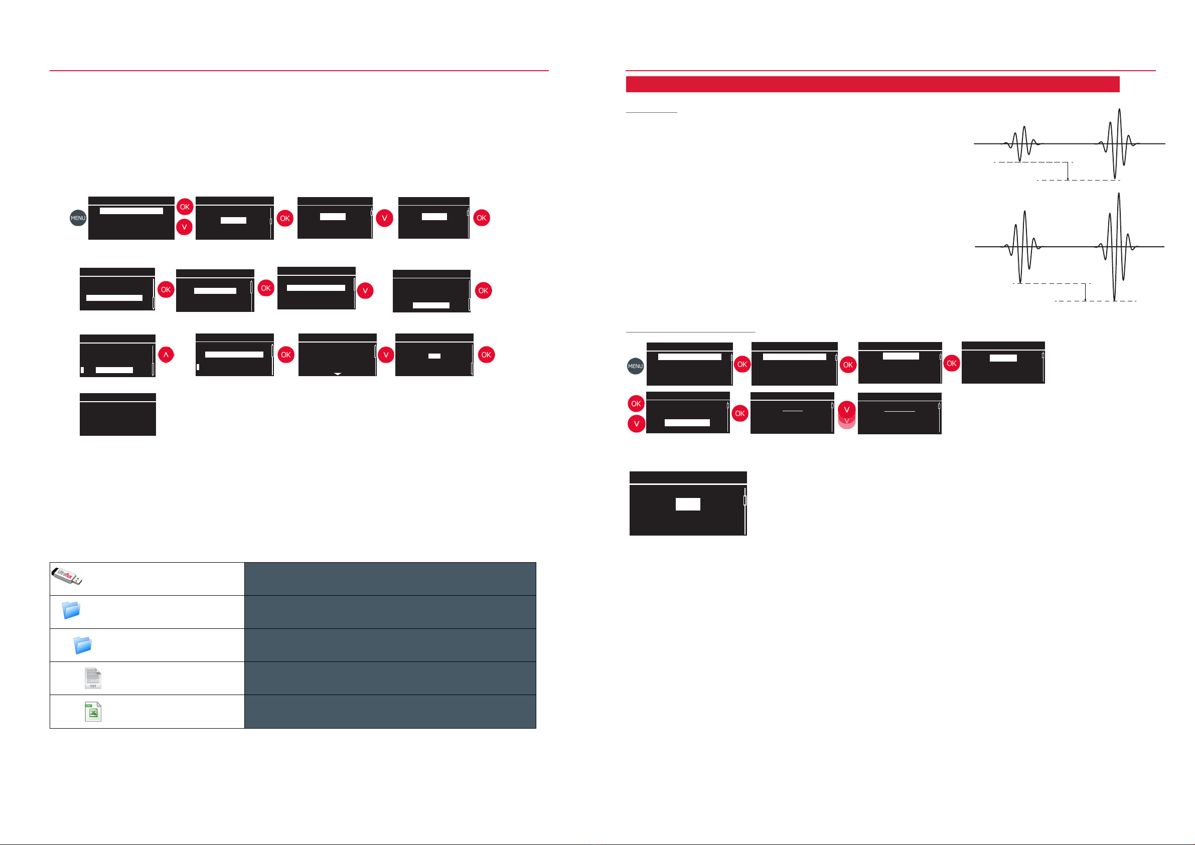
Logger
Settings
Files management
Export to USB
Export selection
Select all
Test rec # 1
File management
Export to USB
Delete files
Logger / Retrieving recordings
Export to USB
Export
Select all
Test rec # 1
Export to USB
Exporter la sélection
Sélectionner tout
Test rec # 1
• Connect the USB key to the unit's USB port.
• In the export to USB submenu, select and mark the le(s) to be exported.
• Export the selection.
When the export is complete, the structure appears as shown below:
The purpose of this procedure is to inform you:
• The path to the menu for retrieving the recording les
• The procedure for selecting the les to be recovered
• The effective recovery of the le(s) on the USB key
• Importing the registration le into Excel
(....)
USB key Physical media: USB key
Ultraflux_Minisonic SN00017 File indicating the serial number of the device (e.g. SN00017)
Logger_Example 1 File indicating the name of the registration (e.g. Example 1)
Example 1_2017.11.22_23h38_config.txt Text le containing the settings of the unit at the time of this recording.
Example 1_2017.11.22_23h38.ind001.log FSpreadsheet le containing logger record data
The information detailed in this chapter corresponds to the EXPERT mode of the menu setting level.
Measuring signal gain adjustment mode
The Minisonic can work on the positive or negative polarity of the
signal.
The Minisonic determines at each reception of the measurement
signal, the Gain to be applied so that the peak of this signal reaches
the detection threshold (example presented on a negative polarity).
To this Gain must be added an additional gain, called Margin,
allowing the peak of the signal to be well above the threshold.
The Minisonic offers several Gain and Margin adjustment modes
Gain
Seuil
Marge
Seuil
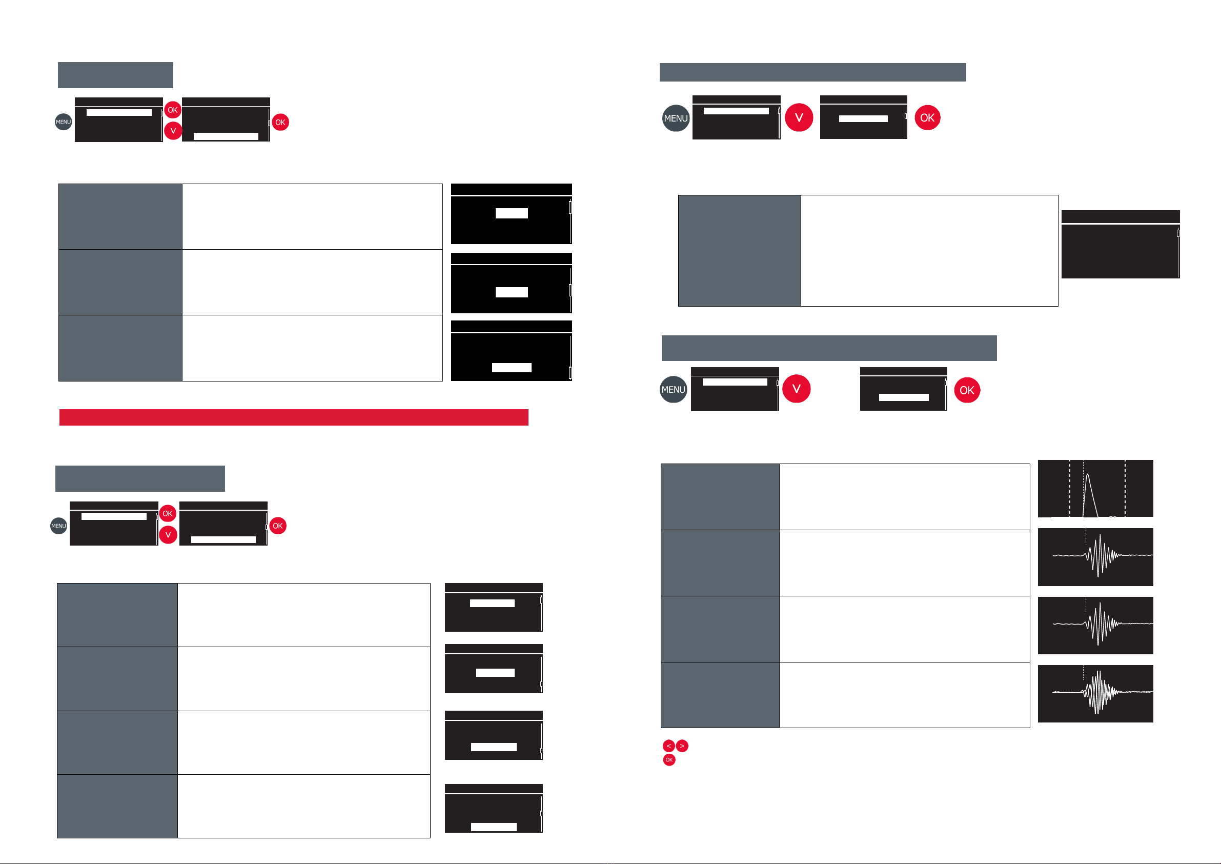
Gain mode
Path to gain type setting
ESC then Auto
Switching from ESC mode (see below) to perform the rst measurement and then
permanently to Automatic mode (see below) for the rest. This mode is to be recommended
for long term measurements on an installation without major changes in the application
conditions.
ESC (Echo Shape Control)
This mode selects the best Gain to be applied to the signal and the most appropriate
Margin.
This mode is to be recommended when using a portable owmeter that performs point
measurements on different applications.
This mode requires a few seconds of signal analysis before indicating the ow rate value.
In case of signal loss due to a disturbance in the measurement conditions ( passing of
bubbles...) the device starts a new ESC.
Automatic
In this mode, only the Gain is determined automatically, the Margin must be indicated
manually. If the Margin is set too high, the ow rate measurement may be performed on
a peak in the middle of the signal. However, the measurement is of better quality if it is
carried out on the rst alternation. This mode is to be recommended on an installation
without strong modications of the application conditions, for long term measurements.
Manual
The Gain and Margin values are determined by the user.
This mode is useful if signal disturbances make the gain too unstable for automatic search.
Foreword
3938
Menu
Measurement cong.
Probe distance
US Signal display
Auto zero
Logger
Settings
File management
Measurement cong.
Measurement settings
Logger
Inputs / Outputs
Settings level
Logger
Settings
File management
Question
Are you sure you want
To export data to
A USB key ?
Question
OK
Cancel
Export to USB
Export selection
Select all
Test rec # 1
(....)
Processing
Please wait
°°°°
Menu
Measurement cong.
Probe distance
US Signal display
Auto zero
Measurement cong.
Measurement settings
Logger
Inputs / Outputs
Settings level
Pipe - A
Measurement settings
Pipe - B
Number of pipes
QT
Pipe
Pipe - A
Fluid
Pairs of probes
Filtring
Probes
SE 1790
Pair of probes 1 - A
Pipe
Pipe - A
Fluid
Pairs of probes
Filtring
Gain mode
ESC
Pair of probes 1 - A
ESC then Auto
ESC
Automatic--
Manual
Other manuals for Ultraflux Minisonic II
1
This manual suits for next models
1
Table of contents
Other FAURE HERMAN Measuring Instrument manuals


Popular Measuring Instrument manuals by other brands

Dwyer Instruments
Dwyer Instruments 477-000-FM Installation and operating instructions

LINSHANG
LINSHANG LS126C user manual

senva
senva EM-PULSE installation instructions

Triplett
Triplett GSM250 user manual

HALaser Systems
HALaser Systems HALscan X20 user manual

Honeywell
Honeywell C7355A1050 Mounting instructions


