LRF-3000S Ultrasonic Transit-time Flow meter
- 2 -
Content
1. Product Overview............................................................................................................................................-4-
1.1. Introduction......................................................................................................................................-4-
1.2. Features of LRF-3000S....................................................................................................................-4-
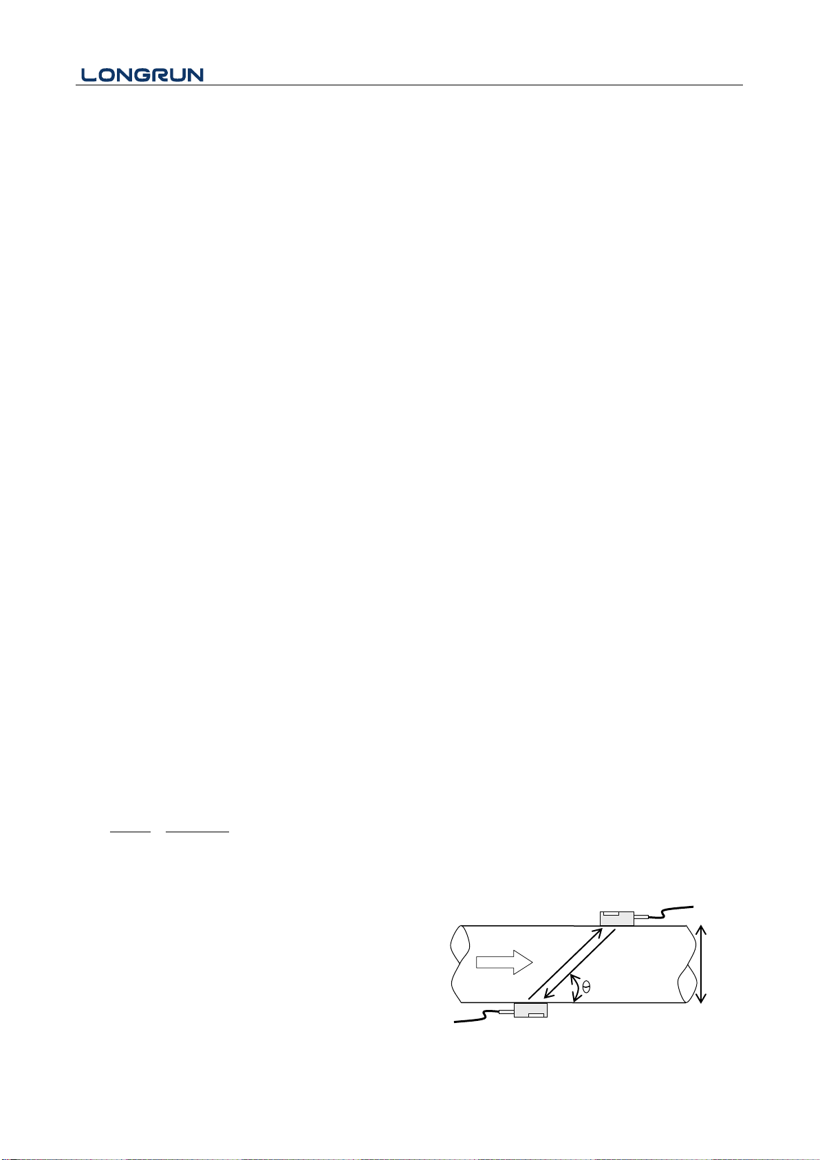
1.3. Theory of Operation.........................................................................................................................-4-
1.4. Specifications.................................................................................................................................- 5 -
2. Connection.....................................................................................................................................................- 6 -
2.1. Wire Connecting............................................................................................................................- 6 -
2.1.1. Power supply option ..............................................................................................................- 6 -
2.1.2. Transmitter Wiring.................................................................................................................- 6 -
2.2. Powering on...................................................................................................................................- 7 -
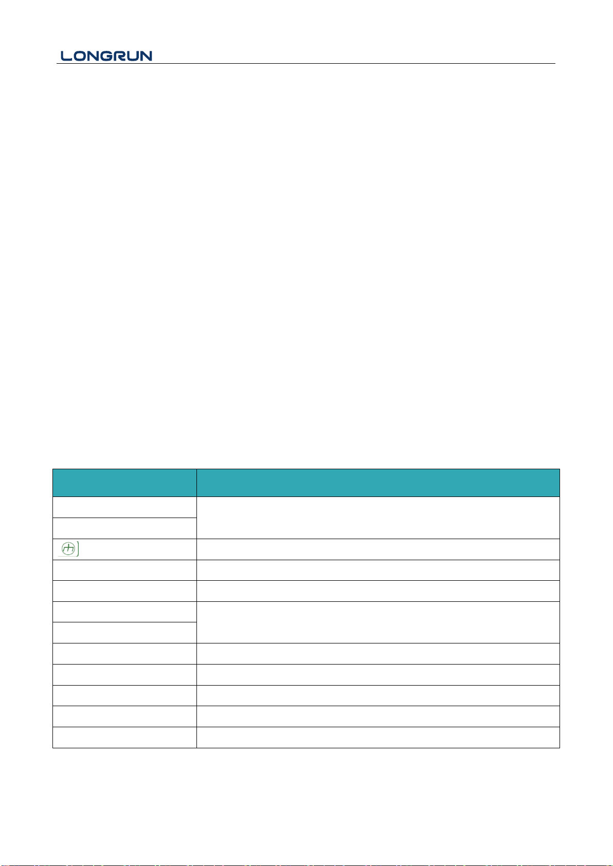
2.3. Keypad Functions..........................................................................................................................- 8 -
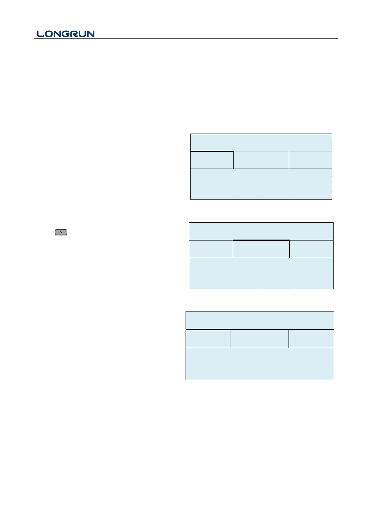
2.4. Keypad Operation............................................................................................................................-8-
3. Quick start..............................................................................................................................................- 9 -
3.1. Basic settings.................................................................................................................................- 9 -
3.2. Measurement Site Selection.........................................................................................................- 10 -
4. Transducer Installation ........................................................................................................................- 13 -
4.1. Transducer Installation.................................................................................................................- 13 -
4.1.1. Transducer Spacing..............................................................................................................- 13 -
1.1.2 Transducer Mounting Methods............................................................................................- 13 -
4.1.3. V Method.............................................................................................................................- 13 -
4.1.4. Z Method .............................................................................................................................- 14 -
4.2. Transducer Mounting Inspection.................................................................................................- 14 -
4.2.1. Signal Strength.....................................................................................................................- 15 -
4.2.2. Signal Quality (Q value)......................................................................................................- 15 -
4.2.3. Total Time and Delta Time ..................................................................................................- 15 -
4.2.4. Transit Time Ratio ...............................................................................................................- 15 -
4.2.5. Warnings..............................................................................................................................- 16 -
5. Operating Instructions .........................................................................................................................- 17 -
5.1. System Normal Identification......................................................................................................- 17 -
5.2. Low Flow Cutoff Value ...............................................................................................................- 17 -
5.3. Zero Settings................................................................................................................................- 17 -
5.4. Scale Factor .................................................................................................................................- 17 -
5.5. System Lock ................................................................................................................................- 18 -
5.6. 4 ~ 20mA Current Loop Output...................................................................................................- 18 -