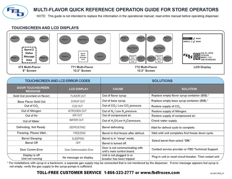
FBD 56 Series Installation guide

PO Box 18597 • San Antonio, Texas 78218 • 210-637-2800
Tech Support: 866-323-2777 • After Hours: 210-445-2344
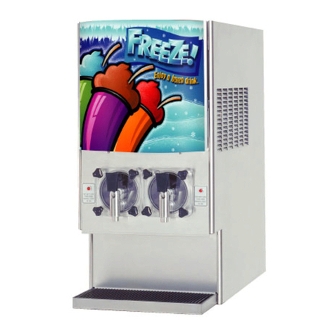
56X Frozen Dispenser
Training Seminar
24-2285-0001
REV M 02/05/2016

Table of Contents
2
FBD 56X specifications…….5
Typical unit setup …………..7
Product flow path …………..8-11
Header assembly…………..12-14
Expansion tank………….….15
Critical settings………….…..16
Beater Motor/Valves………..17-18
Electrical component ….…..19-20
Board descriptions………….21-23
Refrigeration…………………24-26
Keypad operation……………27-29
Menu structure………………30
Menu functions………………31-51
Thaw/Freeze…………………52
Voltage offset adjustment….53-56
Initial start up and freeze…….56-58
E-prom replacement………….59
Status light definition…………60
Electrical diagrams…………..61-62
Troubleshooting
boards……………..……….63-66
Transducers…..……………67
CO2 and solution solenoid..68
LCD messages……………...69-72
Preventive maintenance……73-74
Remote condenser………….75-79
Product warranty…………….80-84

Goals
•The goals of this seminar are:
–To give service technicians basic understanding of systems in
56X frozen dispenser.
–To equip technicians with basic knowledge to operate 56X frozen
dispenser.
–To empower technicians with the understanding of the importance
of “Preventative Maintenance” on 56X frozen dispensers.
–To gain understanding of the Warranty terms and conditions.
3

56X Frozen Dispenser
Specifications
562 563 564
AC RC WC High Cap
AC RC WC High Cap
AC RC WC
Certifications
ES Certified, NSF, UL, CSA, CE, CB, RoHS, Coca-Cola ATM
Refrigerant Charge
42 5 42/30 38 56.5 5 42 45 64 5 60
Compressor [BTU]
15K BTU 19K BTU
15K BTU 19K BTU
19K BTU
Refrigeration Valve
Electronic PWM Expansion Valves
Operating Voltage Range
215 - 245
Current Rating [Amp]
20 30 20 30 30
Pour Capacity Single/Altern
[oz/min]
48/64 75 48/64 75 48/64
IPD time [Min]
12 18 24
Width [in]
17 20.3 26
Depth [in]
32.3
Height (w/o door) [in]
33.9
Height (w/ T door) [in]
41.4
Weight [ lbs]
345 390 460
User Interface
Character Display
Defrost Logic
Customer Dependant: Schedule/Auto Defrost Blockout times features
Control Board
Multiple boards
Diagnostics
9 Most recent error code history
Accessibility
Components accessible from front and sides
Product Expansion (Low Carb/High
Carb)
0.017'/0.020"
4

56X Setup Requirements
FBD FROZEN DISPENSER SETUP FOR FCB
562/563 564
AC RC WC High Cap
AC RC WC
Electrical Requirements
Supply Voltage [Volt]
215 –245 LCD readout should be +/- 2 volts of measured voltage at L1 and L2
Current Rating [Amp]
20 30 30
Incoming Pressure and Flow Requirements
Incoming CO2 (PSI)
70-72
Regulated CO2 (PSI)
22-24
Water Pressure (PSI)
85-92
Syrup Pressure (PSI)
70-72
Active charge Pressure (PSI)
28 - 30
Water Flow Rate at solution module
15oz per 10 second
Brix
13.5 - 15.0
Spacing Requirements
Top
12 inches
Sides
2 inches
Rear
2 inches
Tubing Requirements
CO2
3/8"
Water
3/8"
Syrup
3/8"
5

The Four “Ingredients”
•The four ingredients to Produce a Frozen Beverage
–Water
–Syrup
–CO2
–Electricity
6

Typical FBD Unit Setup
7
Syrup Pump
1 per barrel
CO2
Regulator
Syrup BIB
Water
Source
Electrical
Source
CO2
Source

Product Delivery System
Water and Syrup Mix CO2
Incoming CO2
Mixed solution W/ CO2
Product Delivery System
Model 562 563 564
Solution Module 2 3 4
CO2 Module 2
2 + 1 Extension
2 + 2 Extensions
Expansion Tank 2 3 4
Active Charge Regulator 1
Syrup Pressure Transducer
2 3 4
CO2 Pressure Transducer 2
Water Pressure Transducer
1
Tank Pressure Transducer
2 3 4
Dispensing Valve 2 3 4
Solenoid 4 6 8
8

Complete Header Assembly
9
Water Tank Syrup Tank Syrup
Regulated CO2

Flow Rate Adjustment
•Turning Clockwise
-Increases flow rate
•Turning Counter Clockwise
-Decreases flow rate
10
Syrup Flow
Adjustment
Water Flow
Adjustment
FrontView
TopView
Water Inlet Solution Outlet
Syrup Inlet
Tank Pressure
Transducer
Sample Outlet
Sample Valve
Syrup
Pressure
Transducer
Water Pressure
Transducer
Solution Mixing Module

Importance of Water Flow Rate
The importance of water flow rate (1.5oz/sec) is:
1. Helps calculate syrup consumption, cups sold and revenue.
2. Prevents drink quality issues based on solution and CO2 ratio
•CO2 orifice setting is configured to specific water flow rate
–High water flow rate leads to high solution flow rate and thus, low CO2 in
the product
–Low water flow rate leads to low solution flow rate and thus, high CO2 in the
product
11

CHECK VALVE FAILURE
DIAGNOSTICS
•Usual false diagnostics are:
1. Control board failure
2. Harness failure
3. Transducer failure
•The check valve failure symptoms are:
1. Water pressure and syrup pressure are within +/- 1 psi difference
2. Can’t brix properly
3. Low brix in barrel, and can lead to beater low, frosty compressor, short
cycle, and compressor run too long
12

CO2Module
13
CO2Inlet TopView
FrontView
Regulated
CO2 Pressure
Transducer
Solenoid
Regulated
CO2 Outlet
CO2Pressure Settings
Incoming
•70 –72 psi
•Regulated
•60 +/- 2 psi
CO2 Pressure
Transducer
Pressure
Regulator
CO2 Extension
Module

Importance of CO2 Flow Rate
•Importance of CO2 flow rate are:
–High incoming CO2 can cause damage to the water pump
–Creates different profiles of frozen product
–Prevents drink quality issues based on solution and CO2 ratio
1. Low regulated CO2 leads to low CO2 flow rate, and low CO2 in the
product.
2. High regulated CO2 leads to high CO2 flow rate, and High CO2 in the
product
14

15
•Manually activate “faulty” solenoid, if doesn’t properly actuate
•Disconnect harness from solenoid and measure supply power, range
from 22VAC to 28VAC
•0 volt indicates faulty relay board
•22VAC to 28VAC indicates faulty solenoid
• Faulty “shorted” solenoid will lead to a burned relay board. When
required check and replace relay board.
Troubleshooting Solenoids

Active Charge System
16
Product area
before freezing
Product area
after freezing
Diaphragm
70psi 30 psi
Active Charge Regulator
CO2

Importance of Active Charge
System
•Controls the freeze and thaw of product
•Maintains pressure stability of product barrel to prevent P-
Max Condition
–Below 28 Psig the expansion tank will be filled with product not allowing for
expansion to continue, resulting in a P-Max.
–Higher than 38 Psig will also cause P-Max because of the dead band of the
active charge regulator
•Active Charge Regulator set at 30 psig.
–Turn off machine, and dispensing product out of barrel until tank pressure of 0
Psig
–Measure pressure at active charge regulator with standard tire gauge
17

P-MAX DIAGNOSTICS
•Active Charge Assembly
–Drain Barrel until tank pressure is 0 Psi
–Verify active charge regulator is 2 to 4 Psi above the “FULL” pressure
using tire gauge, adjust if needed.
•Expansion Tank
–Verify if there is a torn bladder by determining whether syrup is on
CO2 side of expansion tank
•Solution & CO2 Module
–Check solenoid seal for tear
–Check solenoid seating is properly installed
•Pressure Transducer Offset or Harness
–Check power to pressure transducer is 3.3 DCV
–Plug into the known pressure and verify pressure readout
18

P-MAX DIAGNOSTIC FLOW
CHART
19

Product Dispensing Valves
DDV Valve
ADA DDV Valve
SDV Valve
20
This manual suits for next models
3
Table of contents
Other FBD Dispenser manuals
Popular Dispenser manuals by other brands

Prince Castle
Prince Castle McDONALD'S 398-B quick start guide

Franke
Franke EXOS618EX Installation and operating instructions

diversey
diversey J-Fill Sink Mizer SS owner's guide

Tork
Tork 570020A Service and parts manual

Air Wolf
Air Wolf Lobo Series manual

DEMA
DEMA 692T FOAM STATION I Installation instruction