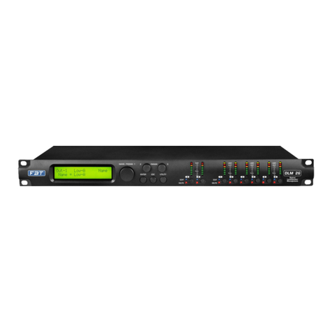
Fbt DLM 260 User manual

PROC
M A D E I N C H I N A
DIGITAL LOUDSPEAKER MANAGEMENT
DLM 260 / DLM 480
OPERATING MANUAL
Code: 46555
EDIT
MUTE
A B 1 23 4 5 6
LIMIT
+12 dBu
0 dBu
-12 dBu
SIG
MUTE
LIMIT
+12 dBu
0 dBu
-12 dBu
SIG
MUTE
LIMIT
+12 dBu
0 dBu
-12 dBu
SIG
MUTE
LIMIT
+12 dBu
0 dBu
-12 dBu
SIG
MUTE
NAVIG. / PARAM. 1 PARAM. 2 PARAM. 3
ENTER ESC UTILITY
EDIT
MUTE
CLIP CLIP CLIP CLIP
DIGITAL LOUDSPEAKER MANAGEMENT
DLM 260
USB
LIMIT
+12 dBu
0 dBu
-12 dBu
SIG
MUTE
CLIP
LIMIT
+12 dBu
0 dBu
-12 dBu
SIG
MUTE
CLIP
LIMIT
+12 dBu
0 dBu
-12 dBu
SIG
MUTE
LIMIT
+12 dBu
0 dBu
-12 dBu
SIG
MUTE
LIMIT
+12 dBu
0 dBu
-12 dBu
SIG
MUTE
CLIP CLIP CLIP
LIMIT
+12 dBu
0 dBu
-12 dBu
SIG
MUTE
CLIP
DLM 480 DIGITAL LOUDSPEAKER MANAGEMENT
NAVIG. / PARAM. 1 PARAM. 2 PARAM. 3
ENTER ESC UTILITY
A B C D 1 2 345 6 7 8
EDIT
MUTE
EDIT
MUTE USB


DLM 260 / DLM 480 Operang Manual
Version: 1.1 EN - 07/2023 - Code: 46555
Soware ver. 0.3.3
Keep this document in a safe place so that it is available for future reference.
We recommend you to regularly check the FBT website for the latest version of this document.
When reselling this product hand over this document to the new owner.
FBT Eleronica SpA - 62019 Recana (Italy)
- info@t.itwww.t.it
• Two/four balanced XLR inputs with up to 12dB of gain, polarity invert, 600ms of delay, 10 band parametric EQ with a choice of 16 filter types individually
selectable for each band
• Convenient front panel controls and LCD display
• Networking opon using either Ethernet or RS485 for larger systems
Roung is freely assignable from the two/four inputs to the six/eight outputs. Input and output equalisaon is available with a choice of 16 filter opons. A
total of 31 IIR EQ is available for each input or 13 IIR EQ + FIR; eight IIR EQ for each output or four IIR EQ + FIR is also available.Many opons for crossover
type include IIR from 6 to 48dB/oct, FIR and Linear Phase with constant group delay. Input and output delay is available to me align components in a
system; RMS and Peak limiters will protect your speakers from damage due to excessive power being applied.
The DLM series are DSP based 2 inputs x 6 output for 260 model and 4 inputs x 8 output for 480 model digital loudspeaker management processor, ideally
suited for fixed installaons and live events.They combine the funcons of a multude of convenonal products in a compact 1 U unit with extensive PC
remote control capabilies.
On input paths, the processing chain sees in cascade: input gain / delay / noise gate / dynamic loudness / filtering secon / RMS compressor.
On output paths the processing chain sees in cascade: output gain / delay / polarity / filtering secon / RMS compressor / peak limiter.
A very useful funcon is the ability to recall enre output channel configuraons and a comprehensive library of output files for FBT products is available
making it very quick ans easy to create exactly the configuraon you need. PC connecvity is available via a front panel USB port but for larger systems with
several processors can use Ethernet or RS 485 network connecons.
• Comprehensive, sophiscated processing opons including EQ, Gate, Delay and liming to opmise and protect a system
• Fully assignable matrix roung of both inputs to any output with aenuaon opon on each roung mode
• Professional 2/4-input, 6/8-output system processors for a wide range of system applicaons
• Six/eight balanced XLR outputs with 128dB gain, polarity invert, 200ms delay, high and low pass filter; 8 band parametric EQ with up a choice of 16 filter
types, indipendent program and peak limiters
FEATURES:
• Front panel USB port for quick and easy PC connecon
• One press mute buons for all inputs and outputs
The processor features 32 user memory locaons to store popular configuraons and sengs can be exported to a file via the dedicated PC applicaon,
either as a back-up or to store more favourite configuraons if the 32 on-board presets are not sufficient.
• 32 user presets to store system configuraons
• Universal switch mode mains PSU accepts 90 to 240V - 50/60Hz
• Output channel preset import funcon to quickly and easily compile a system to suit any applicaon ulising a library of FBT product channel presets
INTRODUCTION
1
INSTALL__________________________________
REAR PANEL______________________________
WASTE-DISPOSAL________________________
SAFETY INSTRUCTIONS___________________
FRONT PANEL____________________________
SUMMARY
2
3
4
5
6
PAG.
SOFTWARE_______________________________
SPECIFICATIONS & DATA__________________
SETTINGS_________________________________
OVERVIEW OF SIGNAL PROCESSING______
CONNECTIONS___________________________
7
21
22
25
42
PAG.

WASTE - DISPOSAL
Where affixed on the equipment or package, the barred waste bin sign
indicates that the product must be separated from other waste at the end
of its working life for disposal. At the end of use, the user must deliver the
product to a suitable recycling centre or return it to the dealer when
purchasing a new product. Adequate disposal of the decommissioned
equipment for recycling, treatment and environmentally compable
disposal contributes in prevenng potenally negave effects on the
environment and healt and promotes the reuse and/or recycling of
equipment materials. Abusive product disposal by the user is punishable by
law with administrave sancons.
MASTER CARTON
PAPER
PAPER
DISPOSAL
INTERNAL
PROTECTIONS
POLYETHYLENE
PLASTIC
DISPOSAL
BAG
POLYETHYLENE
PLASTIC
DISPOSAL
MANUAL
PAPER
PAPER
DISPOSAL
2

SAFETY INSTRUCTIONS
• Follow all instrucons
• Do not use this apparatus near water
• Install in accordance with the manufacturer's instrucons
• Do not install near any heat sources such as radiators, heat registers,
stoves or other apparatus (including amplifiers) that produce heat
• Do not block any venlaon openings
• Clean only with dry cloth
IMPORTANT SAFETY INSTRUCTIONS
• Read these instrucons
The exclamaon point within an equilateral triangle is intended to alert the
user of the presence of important operang and maintenance (servicing)
instrucons in the literature accompanying the appliance.
The lightning flash with arrowhead symbol within an equilateral triangle is
intended to alert the user to the presence of uninsulated dangerous voltage
within the product's enclosurem, that may be of sufficient magnitude to
constute a risk of electric shock to persons.
• Keep these instrucons
• Heed all warnings
• Do not overload wall outlets and extension cords as this can result in a risk
of fire or electric shock
• This apparatus shall not be exposed to dripping or splashing. No object
filled with liquid such as vases, shall be placed on the apparatus
• The mains plug or an appliance coupler is used as the disconnect device,
so the disconnect device shall remain readily operable
• This apparatus has been designed with Class I construcon and must be
connected to a mains socket outlet with a protecve earthing connecon
(the third grounding prong).
• Refer all servicing to qualified service personnel. Servicing is required
when the apparatus has been damaged in any way, such as power supply
cord or plug is damaged, liquid has been spilled or objects have fallen inot
the apparatus, the apparatus has been exposed to rain or moisture, does
not operate normally, or has been dropped.
• Protect the power cord from being walked on or pinched parcularly at
plugs, convenience receptacles and the point where they exit from the
apparatus
• Do not defeat the safety purpose of the polarized or grounding type plug.
A polarized plug has two blades with one wider than the other; a
grounding type plug has two blades and a third grounding prong. The
wide blade or the third prong are provided for your safety. If the provided
plug does not fit into your outlet, consult an electrician for replacement of
the obsolete outlet
• Unplug this apparatus during lightning storms or when unused for long
periods of me
• This apparatus has been equipped with a rocker-style AC mains power
switch. This switch is located on the rear panel and should remain readily
accessible to the user
To reduce the risk of electric shock do not remove cover (or back), no user
serviceable parts inside, refer servicing to qualified personnel.
CAUTION
Risk of electric shock, do not open.
Pour eviter les risques de choc electrique ne pas enlever le couvercle, aucun
entreen de pieces interieures par l'usager. Confier l'entreen au personnel
qualifie.
Risque de choc electrique ne pas ouvrir.
WARNING: This equipment has been designed be installed by qualified
professionals only ! there are many factors to be considered when installing
professional sound reinforcement systems, including mechanical and
electrical consideraons, as well as acousc coverage and performance.
FBT strongly recommends that this equipment be installed only by a
professional sound installer or contractor.
WARNING: To reduce the risk of fire or electric shock do not expose this
appliance to rain or moisture.
CAUTION: Internal lithium baery. Danger of explosion if baery is
incorrectly replaced. Replace only with the same or equivalent type.
3

INSTALL
For each input channel (A/B/C/D) is a female XLR connector. Even channel
numbers are for analogue inputs only.
Analog signal input:
The HOT, "+" or "in phase" connecon should be made to pin 2 of the XLR
connector.
Pin 1 of the XLR connector is internally connected to the chassis.
The AC voltage provided by the audio processor with built-in global voltage
operaon must be within ±10% of the specified line voltage (90/240V~). The
third pin (grounding pin) on the power cord that comes with the package is a
necessary safety component; please do not try to disable the ground
connecon by using an adapter or other methods.
AC POWER INPUT
SIGNAL INPUT AND OUTPUT
Like all digital signal processing equipment, the signal level supplied to the
unit must be appropriate to avoid working in a low signal-to-noise rao or
distoron. The DLM series processors can accept up to +20dBu analog signal
level, which is greater than the linear output level of most mixers, so the
impact of this type of problem is reduced. When performing equalizaon
processing, pay aenon to the boosted gain value not to be too large, so as
to avoid the gain of the unit from causing digital clipping (of course, you can
use the built-in an-clipping funcon to prevent this event from happening).
It must be noted that the maximum input level in the specificaon is a clipping
level, not a safe praccal level. It must be ensured that the clipping level is not
lower than the next device in the signal chain and a certain margin must be
le during use.
The COLD, "-" or "out of phase" connecon should be made to pin 3 of the
XLR connector.
INPUT XLR BALANCED CONNECTION
INPUT XLR UNBALANCED CONNECTION
4

3) PRAM.2/ESC: the knob is used for changing the values or the status of a
parameter edited within the specific menu page, accessed through the
PARAM.1/ENTER controls; when pressed the buon funcon a higher
level of the menu is entered or an edited parameter's value is NOT
confirmed.
7) USB type B interface for PC connecon
2) PARAM.1/ENTER: the knob is used for the selecon of the main pages of
the several menus; when pressed the buon funcon a lower level of the
menu is entered or an edited parameter's value is confirmed.
4) PARAM.3/UTILITY: the knob is used for changing the values or the status
of a parameter edited within the specific menu page, accessed through the
PARAM.1/ENTER controls; when pressed the buon funcon a ulity
menu is entered for the DLM 260 / DLM 480 general seng ( the
navigaon within the several "ulity" menus is done using the
PARAM.1/PARAM.2 knobs.
8) INPUT CHANNEL SELECTION KEY: short press this key to edit the
parameters of the input channel processes (Gain, Polarity, Delay,
Parametric EQ / RMS Compressor) or general parameters as the channel
name. Press and hold for three seconds to mute the current channel.
1) 2 * 24 alphanumeric display
5) INPUT SIGNAL LEVEL METERS: these meters display the Input signal
level before the Input Gain: MUTE does not affect the displayed level; the
MUTE status is shown by the "mute led" which turns red when the related
channel is muted; when the SIG led is on, it means the input signal reaches
the -40dBu; -12dBu, 0dBu, +6dBu, +12dBu represent the actual RMS
value of the signal; the CLIP/OVER led is on to indicate that the signal is
exceeding the maximum level before the A/D analog-to-digital
conversion OR that an internal Overflow is occurring due to excessive
added gain on the signal path (normally the Overflow is controlled by an
internal process and doesn't bring to signal distoron, but need to
decrease the signal level along the path); the LIMIT light will turn on when
the Input RMS Compressor is operang a dynamic control.
9) OUTPUT CHANNEL SELECTION KEY: short press this key to edit the
parameters of the output channel processes (Gain, Polarity, Delay, Xover,
Parametric EQ / RMS compressor) or general parameters as the channel
inputs to output channel Matrix. Press and hold for three seconds to mute
the current channel.
6) OUTPUT SIGNAL LEVEL METERS: these meters display the Output signal
level before the output Gain, therefore aer the all processes: MUTE
affects the displayed level; the MUTE status is shown by the Mute led
which turns red when the related channel is muted; when the SIG led is on,
it means the input signal reaches the -40dBu; -12dBu, 0dBu, +6dBu,
+12dBu represent the actual RMS value of the signal; the OVER led is on
to indicate that an internal Overflow is occurring due to excessive added
gain on the signal path ( normally the Overflow is controlled by an internal
process and doesn't bring to signal distoron, but need to decrease the
signal level along the path); the LIMIT light will turn on when the Output
RMS Compressor or/and the Output Peak Limiter is/are operang a
dynamic control.
FRONT PANEL
1 2 3 4 5 6
8 9
7
EDIT
MUTE
A B 1 23 4 5 6
LIMIT
+12 dBu
0 dBu
-12 dBu
SIG
MUTE
LIMIT
+12 dBu
0 dBu
-12 dBu
SIG
MUTE
LIMIT
+12 dBu
0 dBu
-12 dBu
SIG
MUTE
LIMIT
+12 dBu
0 dBu
-12 dBu
SIG
MUTE
NAVIG. / PARAM. 1 PARAM. 2 PARAM. 3
ENTER ESC UTILITY
EDIT
MUTE
CLIP CLIP CLIP CLIP
DIGITAL LOUDSPEAKER MANAGEMENT
DLM 260
USB
5

REAR PANEL
1 2 3 4 5 6
1) ON/OFF power switch.
2) AC power input, standard C13 interface; please ensure that the grounding
pin of the power supply is well grounded, otherwise an electric shock
accident may occur.
3) The LAN control port supports TCP/UPD protocol, and the IP address is
automacally obtained by DHCP by default.
4) RS485 protocol interface, providing 1 input and 1 output dual interface,
which can be used to connect soware and also be used for central control
protocol transmission; more....the Figure has to be set below the following
line where wiring is defined as fig:
6) ANALOG SIGNAL INPUT INTERFACE: processor audio signal input,
maximum input level +20dBu, input impedance 20kOhm.
5) ANALOG SIGNAL OUTPUT INTERFACE: processor audio signal output,
maximum output level +18dBu, minimum load 100 Ohm.
ETHERNET RS 485
I
N
O
U
T
OUTPUTS
1
2
3456 AB
INPUTS
DLM 260
Designed in Italy by FBT Eleronica SpA
Made in China
CAUTION
AC 90-240V
50/60Hz
max. 30W
6

SETTINGS
NAVIG. / PARAM. 1 PARAM. 2 PARAM. 3
ENTER ESC UTILITY
DIGITAL LOUDSPEAKER MANAGEMENT
SYSTEM SETTINGS
Ulity general menu contains 3 sub-menu system sengs; under UTILITY
MENU turn the PARAM1 navigaon key to select System ulies.
UTILITY MENU
System Utilities
UTILITY MENU
Program Utilities
UTILITY MENU
Network Utilities
INPUT SOURCE SELECTION
Press PARAM1 to enter the secondary sub-menu where you can select
Analog Input or built-in Signal generator.
SYSTEM UTILITY
Input Source
Input Source
Source = Analog Inp
Input Source
Source = Signal Gen
3
3
SIGNAL GENERATOR SETTINGS
Use the PARAM2 knob to select pink noise or white noise and use the
PARAM3 knob to adjust the signal level from -30dBu to +10dBu with a step
if 1dB
ENTER
PUSH
NAVIG. / PARAM. 1 PARAM. 2 PARAM. 3
ENTER ESC UTILITY
DIGITAL LOUDSPEAKER MANAGEMENT
PARAM. 2
PARAM. 3
Select
signal
type
Adjust
signal
level
Signal Generator
Type = Pink L = -30dBu
Signal Generator
Type = White L = -30dBu
Signal Generator
Type = White L = -30dBu
Signal Generator
Type = White L = +10dBu
TurningTurning
PARAM. 2 PARAM. 3
NAVIG. / PARAM. 1 PARAM. 2 PARAM. 3
ENTER ESC UTILITY
DIGITAL LOUDSPEAKER MANAGEMENT
LINK INPUT
For the linked input channel modify the sengs of any one of the linked
channels and the other linked channels will synchronously modify the same
value.
Turn the le and right knobs PARAM2 to select the AB channel, turn
PARAM3 to the right to turn on the selected channel linkage, turn PARAM3
to the le to turn off the selected channel linkage.
LINKAGE OUTPUT
For the input channel aer linkage, modify the sengs of any linkage
channel and the other linkage channels will simultaneously modify the
same value.
ENTER
PUSH
NAVIG. / PARAM. 1 PARAM. 2 PARAM. 3
ENTER ESC UTILITY
DIGITAL LOUDSPEAKER MANAGEMENT
PARAM. 3
PARAM. 2
PARAM. 3
Select
input
channel
Turn on/off
linkage
Turning
PARAM. 2 PARAM. 3
PARAM. 2
PARAM. 3
Link Input
A=OFF B=OFF
Link Input
A=OFF B=ON
TurningTurning
ENTER
PUSH
Select input channel
PARAM. 2 PARAM. 3
Turn on/off linkage
TurningTurning
Link Input
A=OFF B=OFF
Link Input
A=OFF B=OFF
Link Output
1=OFF 2=OFF 3=OFF 4=OFF
Link Output
1=ON 2=OFF 3=OFF 4=OFF
Link Output
1=ON 2=OFF 3=OFF 4=OFF
Link Output
1=ON 2=OFF 3=OFF 4=OFF
Link Output
1=ON 2=ON 3=OFF 4=OFF
Link Output
1=ON 2=OFF 3=OFF 4=OFF
7

SETTINGS
Knob PARAM2 selects the 1234 channnel, turn PARAM3 to the right to
turn on and turn PARAM3 to the le to turn off the linkage.
• Click the PARAM3 buon
For example, if you need to link output channels 3 and 4, the operaon
sequence is:
• Turn right PARAM3 to turn on
• Connue to rotate PARAM2 to the right to select 4 channel
• Rotate the PARAM2 to the right to select 3 channels
• Use the PARAM1 knob to select system
• Click PARAM1 to enter the submenu
• Turn right PARAM3 to turn on
KEEP LINKED CHANNELS LEVEL OFFSET (LINKED BY DCA MODE)
Allows the fader to be link in equal proporons in different posions. When
the proporon of the input or output channels needs to be adjusted as a
whole during use, the default linkage funcon will make the gain of each
channel change along with the first changed channel. If you do not want to
use it if the gain rao changes, you can use this funcon, similar to the
DCA/VCA groups.
ENTER
PUSH
NAVIG. / PARAM. 1 PARAM. 2 PARAM. 3
ENTER ESC UTILITY
DIGITAL LOUDSPEAKER MANAGEMENT
PARAM. 2
PARAM. 3
Select
output
channel
Enable
Disable
linkage
Linked Channel Mode
Offset INP=OFF OUT=OFF
Linked Channel Mode
Offset INP=ON OUT=OFF
Linked Channel Mode
Offset INP=ON OUT=OFF
Linked Channel Mode
Offset INP=ON OUT=ON
Linked Channel Mode
Offset INP=N/A OUT=N/A
TurningTurning
PARAM. 2 PARAM. 3
When the channel linkage is not turned on, this funcon is not available.
This funcon can prevent the loud sound pressure from the loudspeaker
from frightening the staff when switching presets.
RECALL MODE (MUTE SAFETY)
When this mode is turned on, the current channel mute state will be
maintained regardless of reading any preset and only the muted state of the
preset will be read when this mode is turned off.
NAVIG. / PARAM. 1 PARAM. 2 PARAM. 3
ENTER ESC UTILITY
DIGITAL LOUDSPEAKER MANAGEMENT
PARAM. 2
Recall Mode
Keep Actual Mutes = OFF
Recall Mode
Keep Actual Mutes = ON
Turning
ENTER
PUSH
ON/OFF
PARAM. 2 PARAM. 3
ON/OFF
Protect the output from distoron Keep the signal aer the processor A/D
will not be distorted and ensure that no distoron occurs in the processor
regardless of any improvement.
NAVIG. / PARAM. 1 PARAM. 2 PARAM. 3
ENTER ESC UTILITY
DIGITAL LOUDSPEAKER MANAGEMENT
PARAM. 2
ON/OFF ON/OFF
Recall Mode
Keep Actual Mutes = ON
Prevent Output Clip
Prevent ENABLE = ON
Turning
PARAM. 2 PARAM. 3
ENTER
PUSH
8

SETTINGS
VIEW FIRMWARE VERSION
You can check the firmware version of the current processor, you can go to
the our website to download the latest version of the firmware to get
funcon updates and bug fixes.
Among them FP is the front panel firmware and MB is the main board
firmware.
SYSTEM UTILITY
Firmware Version
Firmware Version
FP = 1.1.1 MB = 0.9
• During the upgrade keep the power supply intact. If the upgrade fails
midway, irreversible data loss may occur.
• The firmware version can be upgraded online
Note :
• Back up all presets before the firmware upgrade
PROGRAM (PRESET) SETTINGS
Under UTILITY MENU turn the PARAM1 knob to select program ulies.
UTILITY MENU:
Program Utilities
Can read previously saved presets from this unit (before pressing read,
please save the current preset, otherwise the current modificaon will be
lost) Add a box.
READ PRESET
NAVIG. / PARAM. 1 PARAM. 2 PARAM. 3
ENTER ESC UTILITY
DIGITAL LOUDSPEAKER MANAGEMENT
PARAM. 1
Recall a Program
P01 : P15 + SUB218
Recall a Program
P01 : P12 + SUB18
Turning
ENTER
PUSH
• Press PARAM1 to wait for the machine to finish reading
• Choose P03
• Turn the PARAM1 knob to the right
• Press PARAM1 to recall a program
Press Ulity
• Turn the PARAM1 knob to the right
For example read the preset 3 from the machine
• Go to Program Ulies and press PARAM1
Save the current input/output /roung and the enre state of the filter to
the machine.
SAVE PRESET
NAVIG. / PARAM. 1 PARAM. 2 PARAM. 3
ENTER ESC UTILITY
DIGITAL LOUDSPEAKER MANAGEMENT
PARAM. 1
PARAM. 3
Select the
next edit
locaon
Select
characters
Save a Program
P01 : FACTORY PRESET
Save a Program
P02 : FACTORY PRESET
Save a Program
P02 : FACTORY PRESET
Save a Program
P02 : PRESENT 1
TurningTurning
PARAM. 2 PARAM. 3
ENTER
PUSH
• Click the PARAM3 buon
• Use the PARAM1 knob to select program
• Press PARAM1 to enter the submenu
• Rotate PARAM1 to the right to select save a program
• Press PARAM1 to enter the next level
• Rotate PARAM1 to the right to select the preset posion (such as P01)
For example, if some changes have been made to the channel and need to
be saved in the processor, follow the steps below to save:
• Press PARAM1 to confirm
9

• Click PARAM1 to confirm
• Click PARAM1 to confirm
• Rotate PARAM3 to the right to select characters
DEVICE NAME
The model of the machine is displayed by default, if you need to modify it
please follow the following order:
• Click the PARAM3 buon
• Use the PARAM1 knob to select Network
• Rotate PARAM1 to Device Name
• Rotate PARAM2 to the right to select the edit character posion
• Rotate PARAM2 to modify the character posion and PARAM3 to select
the character; the maximum allowable 16 characters
• Enter to confirm the modificaon and return
SETTINGS
• Enter the name, PARAM1 select the character posion, PARAM2 select
the character from the gallery below, the maximum allowable 16 characters
• Aer the modificaon is completed, click PARAM1 to save.
NETWORK OPTIONS
The RS485 serial port can be set in the network opon menu and the
network sengs of the machine can be viewed.
Under the sengs, turn the PARAM1 knob, the last opon is the network
seng, the network seng is used to connect to the processor
management soware and provides 3 different interfaces, namely USB,
RS485, LAN; among them the USB connecon is the easiest and the
installaon driver can be directly connected to the PC; RS485 needs to set
the serial port number, ID, baud rate, etc.. and need to be consistent with
the PC sengs; LAN is suitable for mulple processors or long distance
connecons. Through the local area network, stable connecon quality and
high connecon speed can be obtained.
The DLM serie processors provide three connecon methods: USB,
RS485, TCPIP and you can choose any one of them to connect without
choosing.
UTILITY MENU:
Network Utilities
SET RS485 ID NUMBER
For example, the steps to set 485ID to 3 are:
When mulple devices are connected via RS485 protocol, they need to be
set to different ID numbers and cannot be repeated. Aer clicking
PARAM1, rotate PARAM2 to select ID numbers from 1 - 32.
• Click the PARAM3 buon
• Click PARAM1 to confirm
• Rotate PARAM2 to the right to select 03
• Rotate PARAM1 to the right to select RS485 ID
• Click PARAM1 to confirm
• Use the PARAM1 navigaon knob to select Network
• Click PARAM1 to confirm
NETWORK UTILITY
RS-485 ID
RS-485 ID
SET ID=01
RS-485 ID
SET ID=03
PARAM. 1
Turning
NETWORK UTILITY
Device Name
Device Name
Name = DLM 260
ENTER
PUSH
10

SETTINGS
Only the IP Address is displayed here and the default is automac
acquision and the real address will be displayed aer the connecon is
successful. It cannot be modified on the panel.
IP ADDRESS
NETWORK UTILITY
IP Address
IP Address
IP Addr = 000.000.000.000
ENTER
PUSH
The display is 255.255.255.0 which is only for display and cannot be
modified on the panel.
SUBNET MASK
NETWORK UTILITY
Subnet Mask
Subnet Mask
SubMask = 000.000.000.000
ENTER
PUSH
GATEWAY
Only for display, if you need to modify, you need to use the soware to
modify online
NETWORK UTILITY:
Gateway
Gateway
Gatway = 000.000.000.000
LAN MODE
The LAN mode defaults to DHCP and the panel is only used as a display. It
can be modified to DHCP or a fixed IP address through soware. When the
number of devices exceeds a certain number, that is, there are too many
DHCP servers in the LAN, network congeson may occur, so it is
recommended to >5 pcs processors; when connecng at the same me use
the fixed IP method to connect.
NETWORK UTILITY:
LAN Mode
LAN Mode
Mode = DHCP
Click the EDIT buon below the processor level meter to edit the
processing module of the input channel, long press to mute the current
channel.
SETTING OF INPUT CHANNEL
Edit input channel
The level meter of the input channel shows the pre-fader level, that is, it is
not affected by mute; the level meter of the output channel shows the post-
fader level and the level is not displayed aer the mute.
Click the edit buon and the first item displayed is the channel name edit.
CHANNEL NAME EDITING
CH - A Name
Name = CH - A
ENTER
PUSH
PARAM. 3
PARAM. 2
PARAM. 3
PARAM. 3
TurningTurningTurningTurning
The default display, if you need to modify, please follow the following
order:
• Click PARAM1 to confirm
• Rotate PARAM3 to the right to select characters
• Rotate PARAM2 to modify the character posion and PARAM3 to select
the character ; the maximum allowable 6 characters.
• Rotate PARAM2 to the right to select the edit character posion
• Click the Edit buon to edit the channel
• Click PARAM1 to save aer modificaon
CH - A Name
Name = CH - A
CH - A Name
Name = PH - A
CH - A Name
Name = PH - A
CH - A Name
Name = PA - A
CH - A Name
Name = CH - A
CH - A Name
Name = PH - A
CH - A Name
Name = PH - A
CH - A Name
Name = PA - A
CH - A Name
Name = PA - L
11

The noise gate can appropriately suppress the obvious background noise
caused by the accumulaon of front-end equipment or improper system
sengs. On the current page click PARAM1 to edit the overall state of the
noise gate and rotate PARAM2 / PARAM3 to open or close the noise gate.
NOISE GATE
The threshold can be adjusted from -80 dBu to -45 dBu through PARAM2.
The startup me can be adjusted from 1 ms to 1000 ms rotang PARAM2.
The release me can be adjusted from 1 ms to 1000 ms by rotang
PARAM2.
SETTINGS
PARAM. 2
PARAM. 2
TurningTurning
CH - A N. Gate
Enable = OFF
CH - A N. Gate
Threshold = -80
CH - A N. Gate
Enable = ON
CH - A N. Gate
Threshold = -45
PARAM. 2
Turning
CH - A N. Gate
Rel Time = 1ms
CH - A N. Gate
Rel Time = 1.0 sec
PARAM. 2
Turning
CH - A N. Gate
Atk Time = 1ms
CH - A N. Gate
Atk Time = 1.0 sec
The maximum allowable boost gain value can be set separately for UHF and
UHF and the seng of starng speed is also provided.
When the signal strength is low, the boost rao is relavely large; when the
signal strength is high, the boost rao is relavely small or even zero.
In the input channel the working principle is based on the equal loudness
curve of the human ear to compensate and enhance the ultra-low
frequency and ultra-high frequency.
DYNAMIC LOUDNESS BOOSTER
PARAM. 2
Turning
CH - A Loudness
Enable = OFF
CH - A Loudness
Enable = ON
When adjusng the maximum allowable gain the adjustment step of the
knob PARAM2 is 1 dB and the adjustment step of PARAM3 is 0.1 dB.
PARAM. 2
PARAM. 2
TurningTurning
CH - A Loudness
Lo - MaxBoost = 0.0 dB
CH - A Loudness
Hi - MaxBoost = 0.0 dB
CH - A Loudness
Lo - MaxBoost = +10.0 dB
CH - A Loudness
Hi - MaxBoost = +10.0 dB
There are three levels of start-up me adjustable, namely fast, medium and
slow.
CH - A Loudness
Atk Speed = SLOW
CH - A Loudness
Atk Speed = MID
CH - A Gain
Gain = -18.0 dB
PARAM. 2
Turning
PARAM. 2
Turning
Controllable gain range from -18 to +12 dB, 0.1 d B step
GAIN
NAVIG. / PARAM. 1 PARAM. 2 PARAM. 3
ENTER ESC UTILITY
DIGITAL LOUDSPEAKER MANAGEMENT
PARAM. 2
Turning
PARAM. 2
Turning
CH - A Gain
Gain = +12.0 dB
POLARITY
The overall polarity can be selected as posive polarity or -180° reverse
polarity, which can be used to match the phase of the loudspeaker or
correct the overall inversion caused by the wrong connecon of the signal
cable.
PARAM. 2
Turning
CH - A Polarity
Polarity = Normal
CH - A Polarity
Polarity = Inverted
12

SETTINGS
DELAY
The input part can provide a maximum delay of 340 milliseconds, which can
be used to delay the alignment of the tower speaker and the main amplifier
speaker with a maximum distance of 115 meters.
NAVIG. / PARAM. 1 PARAM. 2 PARAM. 3
ENTER ESC UTILITY
DIGITAL LOUDSPEAKER MANAGEMENT
PARAM. 3
CH - A Delay
Delay = 0.000 ms
CH - A Delay
Delay = 340.989 ms
Turning
ENTER
PUSH
1 dB step 0.1 dB step
PARAM. 2 PARAM. 3
COMPRESSOR
RMS compressor reduce the start threshold to use the compressor to
control the dynamics of the input signal. Using a lower start me (such as
5ms) and a higher release me (such as 1000ms) can firmly control the input
signal within a certain range, of course, this will bring an obvious sense of
compression (flatness).
Seng different start/release mes in combinaon with music types will
bring different listening feelings, and make up can also be used to
compensate for the loss of loudness; and with a variable knee seng, the
default 0 is the hard knee and the threshold is the compression starng
point; 100% is the so knee when the compression starng point is lower
than the set threshold and gradually exceeds the threshold to achieve full
effect.
Under high compression raos, it is easy to hear unnatural and abrupt
sounds when using hard knees. On the contrary, using so knees can make
the compression transion smoothly and bring a natural sense of hearing.
PARAM. 2
CH - A RMS Cmp
Enable = OFF
CH - A RMS Cmp
Enable = ON
Turning
Compressor switch
PARAM. 2
CH - A RMS Cmp
Threshold = -10.0 dBu
CH - A RMS Cmp
Threshold = +20.0 dBu
Turning
The start threshold can be adjusted from -10dBu to +20dBu.
PARAM. 2
CH - A RMS Cmp
Ratio = 2:1
CH - A RMS Cmp
Ratio = 32:1
Turning
The compression rao can be adjusted from 2:1 to 32:1
PARAM. 2
CH - A RMS Cmp
Knee = 0%
CH - A RMS Cmp
Knee = 100%
Turning
The so and hard inflecon point can be adjusted among which 0% is the
hard inflecon point and 100% is the so inflecon point.
PARAM. 2
CH - A RMS Cmp
Rel Time = 100ms
CH - A RMS Cmp
Rel Time = 15s
Turning
The adjustable range of the release me is: 100ms to 15000ms.
PARAM. 2
CH - A RMS Cmp
Atk Time = 0.1ms
CH - A RMS Cmp
Atk Time = 1s
Turning
The start-up me can be adjusted from 0.1ms to 1000ms.
NAVIG. / PARAM. 1 PARAM. 2 PARAM. 3
ENTER ESC UTILITY
DIGITAL LOUDSPEAKER MANAGEMENT
PARAM. 2
CH - A RMS Cmp
Makeup = 0.0 dB
CH - A RMS Cmp
Makeup = +12.0 dB
Turning
ENTER
PUSH
1 dB step 0.1 dB step
PARAM. 2 PARAM. 3
Provides automac compressor sengs and automacally sets the
compression start threshold
Provide 4 combinaons; when mulple PEQs are needed, 31 bands of PEQ
can be provided at most.
EQUALIZER MODE
PARAM. 2
CH - A EQ Mode
Mode = 31PEQ
Turning
CH - A EQ Mode
Mode = 7TEQ+24PEQ
You can also use the Target EQ+PEQ that
can be saved separately
13

SETTINGS
You can connect the soware to edit the FIR filter, import or generate FIR
high/low/band pass filters according to the guide.
The input channel allows the use to use a 512 taps FIR filter, its operang
sampling rate is 48kHz. But do not do any processing for the signal aer
24000Hz, keep it as it is.
FIR FILTER
When PEQ mode is selected as with FIR filter, this opon can be turned on.
PARAM. 2
CH - A FIR E/N
FIR Enable = OFF
Turning
CH - A FIR E/N
FIR Enable = ON
CH - A FIR E/N
FIR Enable = N / A
EQUALIZER STATE
PEQ overall on/off, TEQ overall on/off
NAVIG. / PARAM. 1 PARAM. 2 PARAM. 3
ENTER ESC UTILITY
DIGITAL LOUDSPEAKER MANAGEMENT
PARAM. 2
PARAM. 3
TEQ
ON
PEQ
ON
CH-A EQ E/N
TEQ E/N=OFF PEQ E/N=OFF
CH-A EQ E/N
TEQ E/N=ON PEQ E/N=OFF
CH-A EQ E/N
TEQ E/N=ON PEQ E/N=OFF
CH-A EQ E/N
TEQ E/N=ON PEQ E/N=ON
TurningTurning
PARAM. 2 PARAM. 3
Note: when PEQ mode is selected as full PEQ, TEQ is not available, that is,
N/A displayed
CH - A EQ E/N
TEQ E/N=N/A PEQ E/N=OFF
TEQ (TARGET EQ)
Types include: BELL, HiShvQ, LoShvQ, LP Q, HP Q.
CH - A TEQ - 01
E / N = ON Type = BELL
CH - A TEQ - 01
Frequency = 4000Hz
CH - A TEQ - 01
Gain = 0.0dB Q = 1.30
• Click the Edit buon of input B
PEQ 1-31
Specific turning of each band of parametric equalizaon, aer Enter, you
can rotate PARAM1 to select the filter type, you can select high and low
Shelf / Bell / High and Low pass/all pass/notch, etc, rotate the PARAM1
buon to enter the specific parameter adjustment, PARAM2 = gain,
PARAM3 = Q value, Frequency and so on.
•Turn PARAM2 to the right to adjust the frequency to 5500Hz, use
PARAM3 to fine-tune to 5506Hz
To add a high-self Q with a frequency of 5506 Hz, a bandwidth of 5.1 and a
gain of -5dB to input channel B, follow the steps below.
• Connue to rotate PARAM1 right to select frequency adjustment
• Rotate PARAM3 to the right to select HiShvQ
• Click PARAM2 to return
• Use PARAM2 to adjust gain and PARAM3 to adjust Q value
• Use the PARAM1 knob to select PEQ1
• Click PARAM1 to enter the edit
• Right-turn PARAM1 to adjust gain and Q value
• Complete and return
PARAM. 3
CH-A PEQ - 01
E / N = ON Type = BELL
CH-A PEQ - 01
E / N = ON Type = HiShv Q
Turning
Types include: BELL, HiShv1, HiShv2, HiShvQ, LoShv1, LoShv2, LoShvQ, LP
1st, LP 2nd, LP Q, HP 1st, HP 2nd, HP Q, Notch, AllPs1, AllPs2.
PARAM. 1
PARAM. 2
PARAM. 3
PARAM. 1
PARAM. 2
PARAM. 3
CH-A PEQ - 01
E / N = ON Type = HiShv Q
CH-A PEQ - 01
Frequency = 27 Hz
CH-A PEQ - 01
Frequency = 5500 Hz
CH-A PEQ - 01
Frequency = 5506 Hz
CH-A PEQ - 01
Gain = 0dB Q = 2.90
CH-A PEQ - 01
Gain = -5.0 dB Q = 2.90
CH-A PEQ - 01
Frequency = 27 Hz
CH-A PEQ - 01
Frequency = 5500 Hz
CH-A PEQ - 01
Frequency = 5506 Hz
CH-A PEQ - 01
Gain = 0dB Q = 2.90
CH-A PEQ - 01
Gain = -5.0 dB Q = 2.90
CH-A PEQ - 01
Gain = -5.0 dB Q = 5.10
TurningTurningTurningTurningTurningTurning
14

SETTINGS
Long press the Edit buon to mute the current channel, the level meter of
the output channel displays the post-fader level and does not display the
level aer mute.
EDIT buon click into the lower level processor can edit the table
processing module output channels.
EDIT OUTPUT CHANNEL
• Rotate PARAM2 to the right to select the edit character posion
• Click PARAM1 to confirm
Channel name edit.
Click the Edit buon and the first item displayed is the channel name edit;
the default display, if you need to modify, please follow the following order:
• Click the channel edit buon
• Rotate PARAM3 to the right to select characters
• Rotate PARAM2 to modify the character posion, PARAM3 to select the
character; the maximum allowable 6 characters.
CHANNEL NAME
• Click PARAM1 to save aer modificaon
NAVIG. / PARAM. 1 PARAM. 2 PARAM. 3
ENTER ESC UTILITY
DIGITAL LOUDSPEAKER MANAGEMENT
Push
INPUT MATRIX
The input matrix allows the user to mix 2 input signals to any output
channel in any rao. The knob PARAM1 selects the AB input source and the
PARAM3 adjusts the gain amount, which can be adjusted from -30 to 0 dB.
NAVIG. / PARAM. 1 PARAM. 2 PARAM. 3
ENTER ESC UTILITY
DIGITAL LOUDSPEAKER MANAGEMENT
PARAM. 1
PARAM. 2
On/Off Gain
CH-1 Source
A:0dB B:OFF C:OFF D:OFF
CH-1 Source
CH - A = ON Gain = 0dB
CH-1 Source
CH - B = OFF Gain = 0dB
CH-1 Source
CH - A = ON Gain = 0dB
CH-1 Source
CH - B = OFF Gain = 0dB
CH-1 Source
CH - B = ON Gain = 0dB
TurningTurning
PARAM. 2 PARAM. 3
NAVIG. / PARAM. 1 PARAM. 2 PARAM. 3
ENTER ESC UTILITY
DIGITAL LOUDSPEAKER MANAGEMENT
ENTER
PUSH
• Press PARAM1
• To rotate PARAM1, select B
The default route of processor is channel AB(CD) pass-through output
1,2,3,4,5,6,(7,8). In actual use it may be necessary to assign one input signal
to mulple output channels, such as roung input channel A to output 1/2
(since output channel 1 has sent 0dB from input A by default, so directly
start from channel 2).
• Press PARAM2 to complete
• Rotate PARAM3 to adjust the gain of input A to 0dB
• Select the PARAM1 navigaon buon to go to the source screen
• Press the select buon for output 2
• Rotate PARAM3 to adjust the gain of input B to minus infinity
• To rotate PARAM1 , select A
15

SETTINGS
GAIN
The controllable gain range is from -18 to +12dB in 0.1dB steps.
NAVIG. / PARAM. 1 PARAM. 2 PARAM. 3
ENTER ESC UTILITY
DIGITAL LOUDSPEAKER MANAGEMENT
PARAM. 2
PARAM. 2
1dB step 0.1dB step
CH-A Gain
Gain = 0.0 dB
CH-A Gain
Gain = 0.0 dB
CH-A Gain
Gain = -18.0 dB
CH-A Gain
Gain = +12.0 dB
TurningTurning
PARAM. 2 PARAM. 3
The overall polarity can be selected as normal polarity or -180° reverse
polarity, which can be used to match the phase of the loudspeaker or
correct the overall inversion caused by the wrong connecon of the signal
cable.
POLARITY
PARAM. 2
CH-1 Polarity
Polarity = Normal
CH-1 Polarity
Polarity = Inverted
Turning
DELAY
The output part provides a maximum delay of 170 milliseconds, which can
be used to align the me between the mul-way units, in a step of 10.4
microseconds / 0.01 milliseconds.
NAVIG. / PARAM. 1 PARAM. 2 PARAM. 3
ENTER ESC UTILITY
DIGITAL LOUDSPEAKER MANAGEMENT
PARAM. 3
1dB step 0.1db step
CH-1 Delay
Delay = 0.000ms
CH-1 Delay
Delay = 169.989ms
Turning
PARAM. 2 PARAM. 3
ENTER
PUSH
RMS COMPRESSOR
It is mainly used to limit the RMS power of the unit. It needs to cooperate
with the AES power provided by the unit manufacturer and the
amplificaon factor of the power amplifier to calculate the threshold; the
aack me is oen determined by the period corresponding to the
frequency of the high-pass filter and the release me is always set to 16
mes the startup me.
For example, the AES power (2h) of a HF driver is 100 was, the impedance
is 16 Ohms, the crossover point is 1000Hz and the amplificaon factor of
the power amplifier is 40dB, then according to P=U2/R, the maximum
input voltage of the unit is 40 volts, divided by the power amplifier
magnificaon is 100 mes, the voltage limit should be acvated when the
signal level is 0.4v, 0.4v is converted to 20log (0.4/0.775) to get -5.84 about
-6dBu, that is, the treshold is -6dBu; the cycle corresponding to the
crossover point 1000 if it is 1ms, then the start me can be set to 1ms and
the release me is 100ms.
PARAM. 2
PARAM. 2
CH-1 RMS Cmp
Enable = OFF
CH-1 RMS Cmp
Threshold = +20.0dBu
CH-1 RMS Cmp
Enable = ON
CH-1 RMS Cmp
Threshold = -6dBu
TurningTurning
The aack me can be adjusted from 0.1ms to 1000ms.
Compressor switch
PARAM. 2
CH-1 RMS Cmp
Atk Time = 10ms
CH-1 RMS Cmp
Atk Time = 1ms
Turning
PARAM. 2
*1ms
PARAM. 3
10ms
The start threshold can bge adjusted from -10dBu to +20dBu
CH-1 RMS Cmp
Rel Time = 100ms
CH-1 RMS Cmp
Ratio = 32:1
Release Time can be adjust from 100ms ~ 15
16

SETTINGS
The compression rao can be adjusted from 2:1 to 32:1
CH-1 RMS Cmp
Knee = 0 %
The so and hard inflecon point can be adjusted among which 0% is the
hard inflecon point and 100% is the so inflecon point.
PARAM. 2
CH-1 RMS Cmp
Makeup = 0.0 dB
CH-1 RMS Cmp
Makeup = +12.0 dB
Turning
Compression compensaon can be set range: 0 ~ 12dB
PEAK LIMIT
For example, using the ** model woofer, it is found that the stroke of the
unit reaches the limit of 12mm at 103 Volts. At this me, the amplifier
magnificaon is 38dB, 103/80=1.2875v, 20log (1.2875/0.775)=4.4, that
is, the peak compressor's the startup threshold is 4.4dBu.
It is mainly used to limit the peak signal and protect the woofer from
mechanical damage caused by the voice coil movement exceeding the
linear stroke. If you need to accurately set the stroke/frequency and voltage
curve of the unit, you can consult the manufacturer of the unit or measure
and obtain data by yourself.
PARAM. 2
CH-1 Peak Lim
Enable = OFF
CH-1 Peak Lim
Enable = ON
Turning
Peak limiter switch
PARAM. 2
CH-1 Peak Lim
Threshold = +20.0 dBu
CH-1 Peak Lim
Threshold = -10.0 dBu
Turning
The threshold can be adjusted from -10 dBu to +20 dBu
PARAM. 2
CH-1 Peak Lim
Rel Time = 1.0s
CH-1 Peak Lim
Rel Time = 100ms
Turning
The adjustable range of the release me is 100ms to 15000ms
PARAM. 2
CH-1 Peak Lim
Atk Time = 1ms
CH-1 Peak Lim
Atk Time = 1sec
Turning
The aack me can be adjusted from 0.1ms to 1000ms
The DLM 260 series has built-in three kinds of crossover filters.
X-OVER MODE
• Linear phase IIR filter, using FBT exclusive algorithm, retains the shape of
the Linkwiz-Raylei/Bessel/Buerworth filter types without phase
distoron, maintaining the linear phase and controlling the me delay at
the same me in a reasonable range, it can directly replace the tradional
IIR filter for speaker frequency division and only need to align the delay.
• FIR finite impulse response filter, allowing users to customize the window
funcon in the soware to generate high-slope, steep filter shapes and also
accept FIR convoluon generated by external third-party soware based
on measurement , which can realize complex filter shapes and mulple
secons, the parameters are equalized and the phase is corrected at the
same me.
• Tra d i o nal IIR fi lte r, in c l u d ing thr e e t y pes of L i n k wiz -
Raylei/Bessel/Buerworth with a maximum slope of 48dB / oct.
Only three modes are displayed here. The specific parameters are adjusted
in the soware high and low pass filter opons, which cannot be adjusted
on the front panel.
CH-1 Out Mode
Mode=Xover - IIR + 8PEQ
CH-1 Out Mode
Mode=Xover - DLM + 8PEQ
CH-1 Out Mode
Mode=Xover - FIR + 8PEQ
CH-1 Out Mode
Mode=Xover - IIR+FIR+4PEQ
IIR mode
Linear phase mode
FIR mode
IIR + FIR mode (only 4 band of PEQ can be used in this mode)
17

SETTINGS
The soware contains 4 combinaons of filter forms, including IIR / LIN
(Linear phase filter) / FIR / IIR+FIR four combinaons are oponal. When a
single IIR / LIN / FIR mode is selected , a total of 8 band PEQ can be used,
while when IIR+FIR filter is selected, only 4 band PEQ can be used.
FIR FILTER
The output channel allows the user to use a 512-taps FIR filter and its
operang sampling rate is 48kHz, but it does not do any processing for the
signal beyond 24000Hz, keep it as it is ( for the FIR filter status switch in the
previous X-over mode).
Select the mode with FIR filter to display ON/OFF.
CH-1 FIR E/N
FIR Enable = N / A
PARAM. 2
CH-1 FIR E/N
FIR Enable = OFF
CH-1 FIR E/N
FIR Enable = ON
Turning
Otherwise it shows unavailable N/A
In IIR mode the type, slope, frequency and other specific parameters of the
high pass filter can be sdjusted.
HIGH PASS FILTER
Click PARAM1 to edit.
PARAM. 2
CH-1 HPF
F = 20Hz Bypass
CH-1 HPF
Frequency 20Hz
CH-1 HPF
Frequency 20Hz
CH-1 HPF
Frequency 20000Hz
Turning
ENTER
PUSH
Tradional filter categories include: Bessel, Buerworth, Linkwitz-Riley,
with a maximum slope of 48dB / oct.
PARAM. 2
CH-1 HPF
Slope = Bypass
CH-1 HPF
Slope = -48dB LR
Turning
-40 ~ -75dB/oct.
It addionally contains NXF (Notched X-over Filter), the slope range is
PARAM. 2
CH-1 HPF
Slope = -48dB LR
CH-1 HPF
Slope = -40dB NXF
CH-1 HPF
Slope = -40dB NXF
CH-1 HPF
Slope = -75dB NXF
Turning
PARAM. 2
Turning
When the combinaon of IIR and FIR filter is selected, the highest slope of
IIR filter is -24dB/oct and only 4 band PEQ are available.
PARAM. 2
CH-1 HPF
Slope = Bypass
CH-1 HPF
Slope = -24dB BS
Turning
LOW-PASS FILTER
In IIR mode the type, slope, frequency and other specific parameters of the
low-pass filter can be adjusted.
PARAM. 3
PARAM. 2
PARAM. 2
CH-1 LPF
F = 20000Hz Bypass
CH-1 LPF
Frequency = 20000Hz
CH-1 LPF
Slope = Bypass
CH-1 LPF
Slope = -40dB NXF
CH-1 LPF
Frequency = 20000Hz
CH-1 LPF
Frequency = 20Hz
CH-1 LPF
Slope = -48dB LR
CH-1 LPF
Slope = -75dB NXF
Turning
Turning
Turning
ENTER
PUSH
When the combinaon of IIR and FIR filter is selected the highest slope of
IIR filter is -24dB/oct and only 4 band PEQ are available.
PARAM. 2
CH-1 LPF
Slope = Bypass
CH-1 LPF
Slope = -24dB BS
Turning
When the LIN (linear phase filter) or FIR filter type is selected the high/low
pass filter cannot be adjusted on the panel, only by soware.
CH-1 HPF
Highpass is Not Actived
CH-1 LPF
Highpass is Not Actived
EQUALIZER ON STATE
PEQ overall on/off
NAVIG. / PARAM. 1 PARAM. 2 PARAM. 3
ENTER ESC UTILITY
DIGITAL LOUDSPEAKER MANAGEMENT
PARAM. 2
CH-1 EQ E / N
Enable = OFF
CH-1 EQ E / N
Enable = ON
Turning
ENTER
PUSH
18
This manual suits for next models
1
Table of contents
Other Fbt Controllers manuals
Popular Controllers manuals by other brands
DOTECH
DOTECH EVC10B Series user manual
Precision Digital Corporation
Precision Digital Corporation ProtEX-MAX PD8-6210 quick start guide
Siemens
Siemens Simatic S7-300 manual
Evolution
Evolution Evotherm H5RO-S Installation and operation manual

Sunlover
Sunlover SL6 AV operating instructions
Ldsolar
Ldsolar TD2210 user manual

Denon
Denon DN-HC4500 - DJ Mixer USB Controller quick start guide
XPG
XPG PRIME BOX manual
Aqua Computer
Aqua Computer VISION User and installation manual
YGE
YGE 150 HV FAI quick start guide
Philips
Philips Dynalite DDBC516FR installation manual

Whelen Engineering Company
Whelen Engineering Company Wireless Traffic Advisor Installation guides
