www.predig.com
7
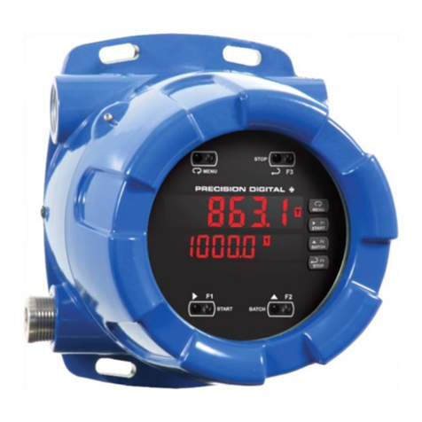
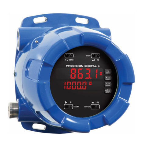
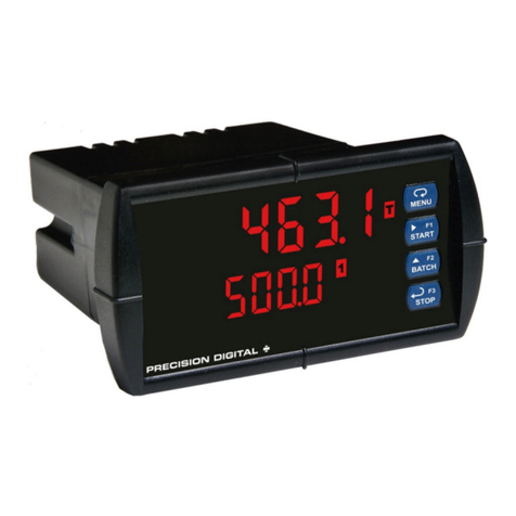
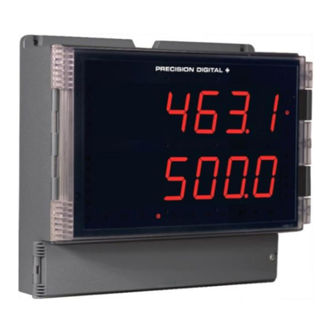
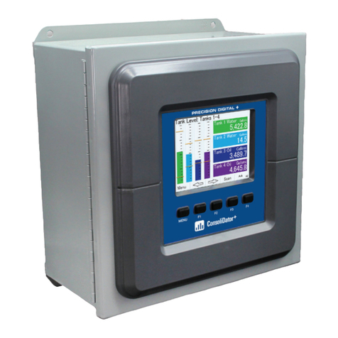
PD8-6210 / PD8-6310 ProtEX-MAXTM Batch Controllers
Max Power Dissipation: Maximum power dissipation limited to 15.1 W.
See PD8-6210/6310 instruction manual for additional details.
Connections: Removable screw terminal blocks accept 12 to 22 AWG wire,
RJ45 for external relays, digital I/O, and serial communication adapters.
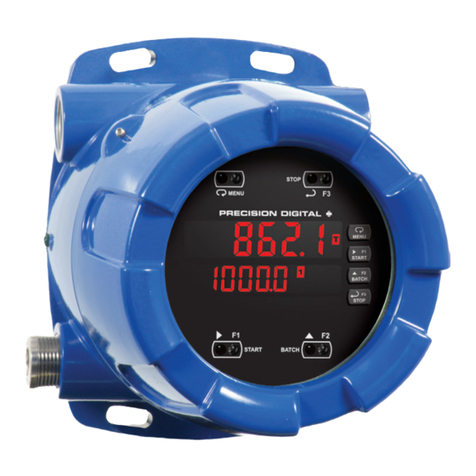
Enclosure: Explosion-proof die cast aluminum with glass window,
corrosion resistant epoxy coating, color: blue. NEMA 4X, 7, & 9, IP68.
Default conduit connections: Four ¾" NPT threaded conduit openings
and two ¾" NPT metal conduit plugs with 12 mm hex key fitting installed.
Additional conduit opening configurations may be available; verify quantity
and sizes on specific device labeling during installation.
Mounting: Four slotted flanges for wall mounting or NPS 1½" to 2½" or DN
40 to 65 mm pipe mounting
Weight: 16.0 lbs (7.26 kg)
Dimensions: 6.42" x 7.97" x 8.47" (W x H x D) (163 mm x 202 mm x 215 mm)
Warranty: 3 years parts & labor
USB Connection: Compatibility: USB 2.0 Standard, Compliant
Connector Type: Micro-B receptacle
Cable: USB A Male to Micro-B Cable
Driver: Windows 98/SE, ME, 2000, Server 2003/2008, XP 32/64-Bit,
Vista 32/64-Bit, Windows 7 32/64-Bit, Windows 10 32/64-Bit
Power: USB Port
PD8-6210 Analog Input
Inputs: Field selectable: 0-20, 4-20 mA, ±10 VDC (0-5, 1-5, 0-10 V),
Modbus PV (Slave)
Accuracy: ±0.03% of calibrated span ±1 count, square root &
programmable exponent accuracy range: 10-100% of calibrated span
Temperature Drift: 0.005% of calibrated span/°C max from 0 to 65°C
ambient, 0.01% of calibrated span/°C max from -40 to 0°C ambient
Signal Input Conditioning: Linear, square root, programmable exponent,
or round horizontal tank volume calculation.
Multi-Point Linearization: 2 to 32 points
Programmable Exponent: 1.0001 to 2.9999
Low-Flow Cutoff: 0-999999 (0 disables cutoff function)
Decimal Point: Up to five decimal places or none: d.ddddd, dd.dddd,
ddd.ddd, dddd.dd, ddddd.d, or dddddd.
Calibration Range:
Input Range
4-20 mA
±10 V
Minimum Span Input 1 & 2
0.15 mA
0.10 V
An error message will appear if input 1 and input 2 signals are too close together.
Input Impedance: Voltage ranges: greater than 1 MΩ.
Current ranges: 50 - 100 Ω(depending on resettable fuse impedance).
Input Overload: Current input protected by resettable fuse, 30 VDC max.
Fuse resets automatically after fault is removed.
PD8-6310 Pulse Input
Inputs: Field selectable: Pulse or square wave 0-5 V, 0-12 V, or 0-24 V @
30 kHz; TTL; open collector 4.7 kΩpull-up to 5 V @ 30 kHz; NPN or PNP
transistor, switch contact 4.7 kΩ pull-up to 5 V @ 40 Hz; coil (sine wave)
40 mVp-p min @ 10 kHz; Modbus PV (Slave)
Low Voltage Mag Pickup (Isolated): Sensitivity: 40 mVp-p to 8 Vp-p
Minimum Input Frequency: 0.001 Hz - Minimum frequency is dependent
on high gate setting.
Maximum Input Frequency: 30,000 Hz (10,000 for Low Voltage Mag Pickup)
Input Impedance: Pulse input: Greater than 300 kΩ @ 1 kHz. Open
collector/switch input: 4.7 kΩ pull-up to 5 V.
Accuracy: ±0.03% of calibrated span ±1 count
Display Update Rate: Total: 10/sec, Rate: 10/sec to 1/1000 sec
Temperature Drift: Rate display is not affected by changes in temperature.
Multi-Point Linearization: 2 to 32 points
Low-Flow Cutoff: 0-999999 (0 disables cutoff function)
Decimal Point: Up to five decimal places or none: d.ddddd, dd.dddd,
ddd.ddd, dddd.dd, ddddd.d, or dddddd.
Calibration: May be calibrated using K-factor, scale using internal
calibration, or calibrate by applying an external calibration signal.
K-Factor: Field programmable K-factor converts input pulses to rate in
engineering units. May be programmed from 0.00001 to 999,999 pulses/unit.
Calibration Range: Input 1 signal may be set anywhere in the range of
the controller; input 2 signal may be set anywhere above setting.
Filter: Programmable contact de-bounce filter, 40 to 999 Hz maximum
input frequency allowed with low speed filter.
Time Base: Second, minute, hour, or day
Low Gate: 0.1-99.9 seconds; this function determines how often the
incoming pulses are calculated and the rate display is updated.
High Gate: 2.0-999.9 seconds; this function determines how long to wait
for pulses before the display goes to zero. This function is used to display
slow pulse rates.
Note: The combination of the low and high gate functions makes it possible to have a fast display
update for fast pulse rates while displaying slow pulse rates, if needed. For example: If the low gate
is set to 1.0 second and the high gate to 999.9 second, with a fast pulse rate the display is updated
every second; with a slow pulse rate the controller is capable of waiting up to 999.9 seconds before
calculating the rate, making it possible to display a very slow rate down to 1 pulse/999.9 second
(0.001 pulse/second).
Batch Controller
Rate Display Indication: 0 to 999999, lead zero blanking. “R” LED
illuminates while displaying rate.
Total Displays & Grand Total Overflow: 0 to 999,999; automatic lead
zero blanking. “T” LED is illuminated while displaying batch total and
“GT” for grand total. Up to 999,999,999 with total-overflow feature. “oF” is
displayed to the left of grand total overflow and ▲ LED is illuminated.
Batch Total Decimal Point: Up to five decimal places or none: d.ddddd,
dd.dddd, ddd.ddd, dddd.dd, ddddd.d, or dddddd.
Total decimal point is independent of rate decimal point.
Totalizer: Calculates total based on rate and field programmable multiplier
to display total in engineering units. Time base must be selected according
to the time units in which the rate is displayed.
Total Conversion Factor: 0.00001 to 999,999
Batch Preset: 0.00001 to 999,999 based on batch total decimal point.
Automatic Batch Restart Delay: 00000.1 to 999.9 seconds. The batch
will automatically restart after completion of the last batch.
Grand Total Rollover: Totalizer rolls over when display exceeds
999,999,999. Relay status reflects the display value.
Grand Total Alarms: Up to seven, user selectable under Setup menu.
Any set point can be assigned to grand total and may be programmed
anywhere in the range of the controller for grand total alarm indication.
Note that Relay 1 should always be assigned to batch control (total).
Grand Total Reset: Via front panel button, external contact closure on
digital inputs, automatically via user selectable preset value and time
delay, or through serial communications.
Grand Total Reset Password: A grand total password may be entered to
prevent resetting the grand total from the front panel.
Non-Resettable Grand Total: The grand total can be programmed as a
non-resettable total by entering the password “050873”.
Caution: Once the Grand Total has been programmed as “non-resettable” the feature cannot be disabled
Relays
Rating: 2 or 4 SPDT (Form C) internal and/or 4 SPST (Form A) external;
rated 3 A @ 30 VDC and 125/250 VAC resistive load; 1/14 HP (≈ 50 W) @
125/250 VAC for inductive loads
Noise Suppression: Noise suppression is recommended for each relay
contact switching inductive loads.
Relay Assignment: Relays may be assigned to batch control, sampling,
rate, or grand total alarms.
Preclose: 0-100% of batch size, individually user programmable for each
additional batch control relay beyond the first.
Alarm Deadband: 0-100% of span, user programmable
High or Low Alarm: User may program any alarm for high or low trip
point. Unused alarm LEDs and relays may be disabled (turned off).
Batching Relay Operation: Single or (2 to 8) multi-relay batching with
optional preclose for multi-stage operation. Each additional relay may be
programmed with an individual preclose value.
Alarm Relay Operation: Automatic (non-latching), latching (requires
manual acknowledge), sampling (based on rate or grand total), pump
alternation control (2 to 8 relays), off (disable unused relays), and manual
on/off control mode.Alarms are active only when the batch is running.
Alarm Relay Reset: User selectable via front buttons, digital inputs, or PC
1. Automatic reset only (non-latching), when input passes the reset point
or total is reset to zero.


