FCW DYNA TIG 201AC/DC User manual

- 1 -
DYNATIG 201AC/DC Operating Manual
CONTENTS
SYMBOL LEGEND---------------------------------------------------------------------------------------------------2
STATEMENT OF WARRANTY------------------------------------------------------------------------------------3
1.0 GENERAL INFORMATION-------------------------------------------------------------------------------4
1.01 Notes, Cautions and Warnings------------------------------------------------------------------------4
1.02 Important Safety Precautions--------------------------------------------------------------------------4
1.03 Transporting methods-----------------------------------------------------------------------------------6
2.0 INSTALLATION RECOMMENDATION----------------------------------------------------------------7
2.01 Electrical Input Connections---------------------------------------------------------------------------8
2.02 Specifications--------------------------------------------------------------------------------------------10
2.03 Duty cycle-------------------------------------------------------------------------------------------------10
3.0 OPERATOR CONTROLS-------------------------------------------------------------------------------11
3.01 DYNA TIG 201AC/DC controls----------------------------------------------------------------------11
3.02 Weld parameter description--------------------------------------------------------------------------13
3.03 Weld parameters for DYNA TIG 201AC/DC------------------------------------------------------14
4.0 SET-UP FOR MMA (STICK) AND GTAW (TIG)----------------------------------------------------15
5.0 POWER SUPPLY CONTROLS INDICATORS AND REATURES-----------------------------16
5.01 Stick welding---------------------------------------------------------------------------------------------17
5.02 DC TIG welding-----------------------------------------------------------------------------------------17
5.03 AC TIG welding------------------------------------------------------------------------------------------17
5.04 DC pulse TIG welding---------------------------------------------------------------------------------17
5.05 AC pulse TIG welding----------------------------------------------------------------------------------18
6.0 BASIC TIG WELDING GUIDE--------------------------------------------------------------------------19
6.01 Electrode Polarity---------------------------------------------------------------------------------------19
6.02 Tungsten Electrode Current Ranges---------------------------------------------------------------19
6.03 Tungsten Electrode Types----------------------------------------------------------------------------19
6.04 Guide for Selecting Filler Wire Diameter----------------------------------------------------------20
6.05 Shielding gas selection--------------------------------------------------------------------------------20
6.06 TIG welding parameters for low carbon & low alloy steel pipe-------------------------------21
6.07 Welding parameters for Aluminum----------------------------------------------------------------- 21
6.08 Welding parameters for steel------------------------------------------------------------------------22
7.0 BASIC ARC WELDING GUIDE------------------------------------------------------------------------23
7.01 Electrode polarity---------------------------------------------------------------------------------------23
7.02 Effects of stick welding various materials---------------------------------------------------------23
8.0 MAINTENANCE--------------------------------------------------------------------------------------------24
9.0 BASIC TROUBLESHOOTING-------------------------------------------------------------------------24
9.01 Check the item and excrescent phenomenon exclusion method---------------------------24
9.02 TIG welding problems---------------------------------------------------------------------------------26
9.03 AC TIG on Aluminum the problem------------------------------------------------------------------27
9.04 Stick welding problems--------------------------------------------------------------------------------27
9.05 Power source problems-------------------------------------------------------------------------------28
10.0 PARTS LIST-------------------------------------------------------------------------------------------------30
11.0 REMARK-----------------------------------------------------------------------------------------------------34
APPENDIX: INTERCONNECT DIAGRAM
- 2 -
DYNATIG 201AC/DC Operating Manual
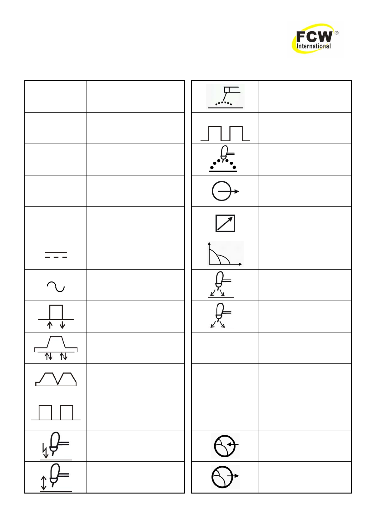
SYMBOL LEGEND
A Amperage Stick (SMAW)
VVoltage Pulse Current Function
(GTAW)
Hz Hertz (frequency) t Spot Time (GTAW)
SEC Seconds Remote outputs control
(Panel/Remote)
%Percent Remote Function
DC (Direct Current) Arc Control (SMAW)
AC (Alternating Current) t
2Gas Post-Flow Time
2T (GTAW) t1Gas Pre-Flow Time
4T (GTAW) VRD Voltage Reduction
Device Circuit
Repeat Function (GTAW) — Negative
Spot Function (GTAW) + Positive
High Frequency Starting
(GTAW)
Gas Input
Lift Start (GTAW)Gas Output

- 3 -
DYNATIG 201AC/DC Operating Manual
STATEMENT OF WARRANTY
LIMITED WARRANTY: "FCW" warrants to customers of its authorized distributors hereafter "FCW" that its products will be free
of defects in workmanship or material. Should any failure to conform to this warranty appear within the time period applicable to
the FCW products as stated below, FCW shall, upon notification thereof and substantiation that the product has been stored,
installed, operated, and maintained in accordance with FCW’s specifications, instructions, recommendations and recognized
standard industry practice, and not subject to misuse, repair, neglect, alteration, or accident, correct such defects by suitable
repair or replacement, at FCW ‘s sole option, of any components or parts of the product determined by FCW to be defective.
The FCW COMPANY MAKES NO OTHER WARRANTY, EXPRESS OR IMPLIED. THIS WARRANTY IS EXCLUSIVE AND IN
LIEU OF ALL OTHERS, INCLUDING, BUT NOT LIMITED TO ANY WARRANTY OF MERCHANTABILITY OR FITNESS FOR
ANY PARTICULAR PURPOSE.
LIMITATION OF LIABILITY: FCW shall not under any circumstances be liable for special, indirect or consequential damages,
such as, but not limited to, lost profits and business interruption. The remedies of the Purchaser set forth herein are exclusive
and the liability of FCW with respect to any contract, or anything done in connection therewith such as the performance or
breach thereof, or from the manufacture, sale, delivery, resale, or use of any goods covered by or furnished by FCW whether
arising out of contract, negligence, strict tort, or under any warranty, or otherwise, shall not, except as expressly provided herein,
exceed the price of the goods upon which such liability is based. No employee, agent, or representative of FCW is authorized to
change this warranty in any way or grant any other warranty.
PURCHASER'S RIGHTS UNDER THIS WARRANTY ARE VOID IF REPLACEMENT PARTS OR ACCESSORIES ARE USED
WHICH IN FCW’S SOLE JUDGEMENT MAY IMPAIR THE SAFETY OR PERFORMANCE OF ANY FCW PRODUCT.
PURCHASER'S RIGHTS UNDER THIS WARRANTY ARE VOID IF THE PRODUCT IS SOLD TO PURCHASER BY
NON-AUTHORIZED PERSONS.
The warranty is effective for the time stated below beginning on the date that the authorized distributor delivers the products to
the Purchaser. Not with standing the foregoing, in no event shall the warranty period extend more than the time stated plus one
year from the date FCW delivered the product to the authorized distributor.
POWER SUPPLIES POWER SUPPLIES & WIRE FEEDERS
MAIN POWER MAGNETICS (STATIC& ROTATING) 1YEAR
ORIGINAL MAIN POWER RECTIFIER 1YEAR
POWER SWITCHING SEMI-CONDUCTORS & CONTROL PC BOARD 1YEAR
ALL OTHER CIRCUITS AND COMPONENTS INCLUDING 1YEAR
BUT NOT LIMITED TO, CONTACTORS, RELAYS,
SOLENOIDS, PUMPS, SWITCHES, MOTORS
Warranty repairs or replacement claims under this limited warranty must be submitted to FCW by an authorized FCW repair
facility within thirty (30) days of purchaser’s notice of any Warranty Claim. No transportation costs of any kind will be paid under
this warranty. Transportation charges to send products to an authorized warranty repair facility shall be the responsibility of the
Purchaser. All returned goods shall be at the Purchaser’s risk and expense. This warranty supersedes all previous FCW
warranties.

- 4 -
DYNATIG 201AC/DC Operating Manual
1.0 GENERAL INFORMATION
1.01 Notes, Cautions and Warnings
Throughout this manual, notes, cautions, and warnings are used to highlight important information. These
highlights are categorized as follows:
NOTE
An operation, procedure, or background information which requires additional emphasis or is helpful in
efficient operation of the system.
CAUTION
A procedure which, if not properly followed, may cause damage to the equipment.
WARNING
A procedure which, if not properly followed, may cause injury to the operator or others in the operating area.
1.02 Important Safety Precautions
WARNING
OPERATION AND MAINTENANCE OF ARC WELDING EQUIPMENT CAN BE DANGEROUS AND
HAZARDOUS TO YOUR HEALTH.
To prevent possible injury, read, understand and follow all warnings, safety precautions and instructions
before using the equipment. Call 86-21-69171135 or your local distributor if you have any questions.
GASES AND FUMES
Gases and fumes produced during the Arc welding or cutting process can be dangerous and hazardous to
your health.
zKeep all fumes and gases from the breathing area. Keep your head out of the welding fume plume.
zUse an air-supplied respirator if ventilation is not adequate to remove all fumes and gases.
zThe kinds of fumes and gases from the arc welding/cutting depend on the kind of metal being used,
coatings on the metal, and the different processes. You must be very careful when cutting or welding
any metals which may contain one or more of the following:
Antimony Arsenic Barium Beryllium Cadmium Chromium Cobalt Copper Lead
Manganese Mercury Nickel Selenium Silver Vanadium
zAlways read the Material Safety Data Sheets (MSDS) that should be supplied with the material you
are using. These MSDSs will give you the information regarding the kind and amount of fumes and
gases that may be dangerous to your health.
zUse special equipment, such as water or down draft welding/cutting tables, to capture fumes and
gases.
zDo not use the welding torch in an area where combustible or explosive gases or materials are
located.
zPhosgene, a toxic gas, is generated from the vapors of chlorinated solvents and cleansers. Remove
all sources of these vapors.

- 5 -
DYNATIG 201AC/DC Operating Manual
ELECTRIC SHOCK
Electric Shock can injure or kill. The arc welding process uses and produces high voltage electrical energy.
This electric energy can cause severe or fatal shock to the operator or others in the workplace.
zNever touch any parts that are electrically “live” or “hot.”
zWear dry gloves and clothing. Insulate yourself from the work piece or other parts of the welding
circuit.
zRepair or replace all worn or damaged parts.
zExtra care must be taken when the workplace is moist or damp.
zInstall and maintain equipment according to NEC code, refer to relative standards
zDisconnect power source before performing any service or repairs.
zRead and follow all the instructions in the Operating Manual.
FIRE AND EXPLOSION
Fire and explosion can be caused by hot slag, sparks, or the arc weld.
zBe sure there is no combustible or flammable material in the workplace.Any material that cannot be
removed must be protected.
zVentilate all flammable or explosive vapors from the workplace.
zDo not cut or weld on containers that may have held combustibles.
zProvide a fire watch when working in an area where fire hazards may exist.
zHydrogen gas may be formed and trapped under aluminum workpieces when they are cut
underwater, or while using a water table. Do not cut aluminum alloys underwater or on a water table
unless the hydrogen gas can be eliminated or dissipated. Trapped hydrogen gas that is ignited will
cause an explosion.
NOISE
Noise can cause permanent hearing loss. Arc welding/cutting processes can cause noise levels to exceed
safe limits. You must protect your ears from loud noise to prevent permanent loss of hearing.
zTo protect your hearing from loud noise, wear protective ear plugs and/ or ear muffs. Protect others
in the workplace.
zNoise levels should be measured to be sure the decibels (sound) do not exceed safe levels.
ARC WELDING RAYS
Arc Welding/ Cutting Rays can injure your eyes and burn your skin. The arc welding/cutting process produces
very bright ultra violet and infra red light. These arc rays will damage your eyes and burn your skin if you are
not properly protected.
zTo protect your eyes, always wear a welding helmet or shield. Also always wear safety glasses with
side shields, goggles or other protective eye wear.
zWear welding gloves and suitable clothing to protect your skin from the arc rays and sparks.
zKeep helmet and safety glasses in good condition. Replace lenses when cracked, chipped or dirty.
zProtect others in the work area from the arc rays. Use protective booths, screens or shields.
1.03 Transporting methods

- 6 -
DYNATIG 201AC/DC Operating Manual
These units are equipped with a handle for carrying purposes.
WARNING: ELECTRIC SHOCK can kill.
DO NOT TOUCH live electrical parts. Disconnect input power conductors from de-energized supply
line before moving the welding power source.
WARNING: FALLING EQUIPMENT can cause serious personal injury and
equipment damage.
zLift unit with handle on top of case.
zUse handcart or similar device of adequate capacity.
zIf using a fork lift vehicle, place and secure unit on a proper skid before transporting.

- 7 -
DYNATIG 201AC/DC Operating Manual
2.0 INSTALLATION RECOMMENDATION
Installation Environment
DYNA TIG is designed for use in hazardous environments.
Examples of environments with increased hazardous environments are -
In locations in which freedom of movement is restricted, so that the operator is forced to perform the work
in a cramped (kneeling, sitting or lying) position with physical contact with conductive parts; In locations which
are fully or partially limited by conductive elements, and in which there is a high risk of unavoidable or
accidental contact by the operator, or in wet or damp hot locations where humidity or perspiration
considerable reduces the skin resistance of the human body and the insulation properties of accessories.
Environments with hazardous environments do not include places where electrically conductive parts in
the near vicinity of the operator, which can cause increased hazard, have been insulated.
Installation Location
Be sure to locate the welder according to the following guidelines:
zIn areas, free from moisture and dust. zIn areas, not subjected to abnormal vibration or
shock.zIn areas, free from oil, steam and corrosive
gases. zPlace at a distance of 304.79mm or more from
walls or similar that could restrict natural airflow
for cooling.
zIn areas, not exposed to direct sunlight or rain.
zAmbient temperature: between -10 degrees C
to 40 degrees C.
WARNING 1
FCW advises that this equipment be electrically connected by a qualified electrician.
The following Primary Current recommendations are required to obtain the maximum welding current and
duty cycle from this Power Supply:
Minimum primary current
circuit size Current & Duty Cycle
Model Primary supply lead
size TIG STICK TIG STICK
DYNATIG 201AC/DC Minimum 3.2mm2220V/32A 1ph 220V/34A 1ph 200A/18V@60% 160A/26.4V@100%
Table 1 220V primary current circuit sizes to achieve maximum current

- 8 -
DYNATIG 201AC/DC Operating Manual
2.01 Electrical Input Connections
WARNING: ELECTRIC SHOCK can kill; SIGNIFICANT DC VOLTAGE is
present after removal of input power.
DO NOT TOUCH live electrical parts
SHUT DOWN welding power source, disconnect input power employing lockout/ tagging procedures.
Lockout/ tagging procedures consist of padlocking line disconnect switch in open position, removing fuses
from fuse box, or shutting off and red-tagging circuit breaker or other disconnecting device.
Electrical Input Requirements
Operate the welding power source from a single phase 50/ 60 Hz, AC power supply. The input voltage must
match one of the electrical input voltages shown on the input data label on the unit nameplate. Contact the
local electric utility for information about the type of electrical service available, how proper connections
should be made, and inspection required.
The line disconnect switch provides a safe and convenient means to completely remove all electrical power
from the welding power supply whenever necessary to inspect or service the unit.
According to Table 1 and below as a guide to select line fuses for the disconnect switch.
Input Voltage Fuse Size
220/240V AC 40 Amps
Table 2
Notice: Fuse size is based on not more than 200 percent of the rated input amperage of the
welding power source (Based on Article 630, National Electrical Code).
Figure 1 Electrical input connections

- 9 -
DYNATIG 201AC/DC Operating Manual
Input Power
Each unit incorporates an INRUSH circuit and input voltage sensing circuit. When the MAIN CIRCUIT
SWITCH is turned on, the inrush circuit provides a pre-charging of the input capacitors. The welding machine
will turn on after the input capacitors have charged to full operating voltage (after approximately 1.5 seconds).
Introduction
The importance of correct installation of high frequency welding equipment cannot be overemphasized.
Interference due to high frequency initiated or stabilized arc is almost invariably traced to improper installation.
The following information is intended as a guide for personnel installing high frequency welding machine.
Warning
Explosives
The high frequency section of this machine has an output similar to a radio transmitter. The machine
should NOT be used in the vicinity of blasting operations due to the danger of premature firing.
Computers
It is also possible that operation close to computer installations may cause computer malfunction.
High Frequency Interference
Interference may be transmitted by a high frequency initiated or stabilized arc welding machine in the
following ways:
Direct Radiation
Radiation from the machine can occur if the case is metal and is not properly grounded. It can occur
through apertures such as open access panels. The shielding of the high frequency unit in the
Power Source will prevent direct radiation if the equipment is properly grounded.
Transmission via the Supply Lead
Without adequate shielding and filtering, high frequency energy may be fed to the wiring within the
installation (mains) by direct coupling. The energy is then transmitted by both radiation and
conduction. Adequate shielding and filtering is provided in the Power Source.
Radiation from Welding Leads
Radiated interference from welding leads, although pronounced in the vicinity of the leads,
diminishes rapidly with distance. Keeping leads as short as possible will minimize this type of
interference. Looping and suspending of leads should be avoided where possible.
Re-radiation from Unearthed Metallic Objects
A major factor contributing to interference is re-radiation from unearthed metallic objects close to the
welding leads .Effective grounding of such objects will prevent re-radiation in most cases.

- 10 -
DYNATIG 201AC/DC Operating Manual
2.02 Specifications
MODEL DYNA TIG 201AC/DC
Input voltage and
frequency and phases 220V/240V 50/60Hz 1ph
KVA @ max output 7.0kVA
Max current 200A
Output current range
TIG 10~200A
Output current range
MMA 10~160A
Open circuit voltage 56V
Pulse frequency 2Hz/250Hz
Down slope time 0-5S
Post flow time 0-5S
Duty cycle at 40℃60%
Weight 22kg
Dimensions 420x180x485(mm)
Table 3
2.03 Duty cycle
The duty cycle of a welding power source is the percentage of a ten (10) minute period that it can be
operated at a given output without causing overheating and damage to the unit. If the welding amperes
decrease, the duty cycle increases. If the welding amperes are increased beyond the rated output, the duty
cycle will decrease.
WARNING: Exceeding the duty cycle ratings will cause the thermal overload
protection circuit to become energized and shut down the output until has
cooled to normal operating temperature
Continually exceeding the duty cycle ratings
can cause damage to the welding power source.
NOTICE
:
Due to variations that can occur in manufacture products, claimed performance, voltages, ratings, all
capacities, measurements, dimensions and weights quoted are approximate only. Achievable capacities and
ratings in use and operation will depend upon correct installation, use, applications, maintenance and service.
- 11 -
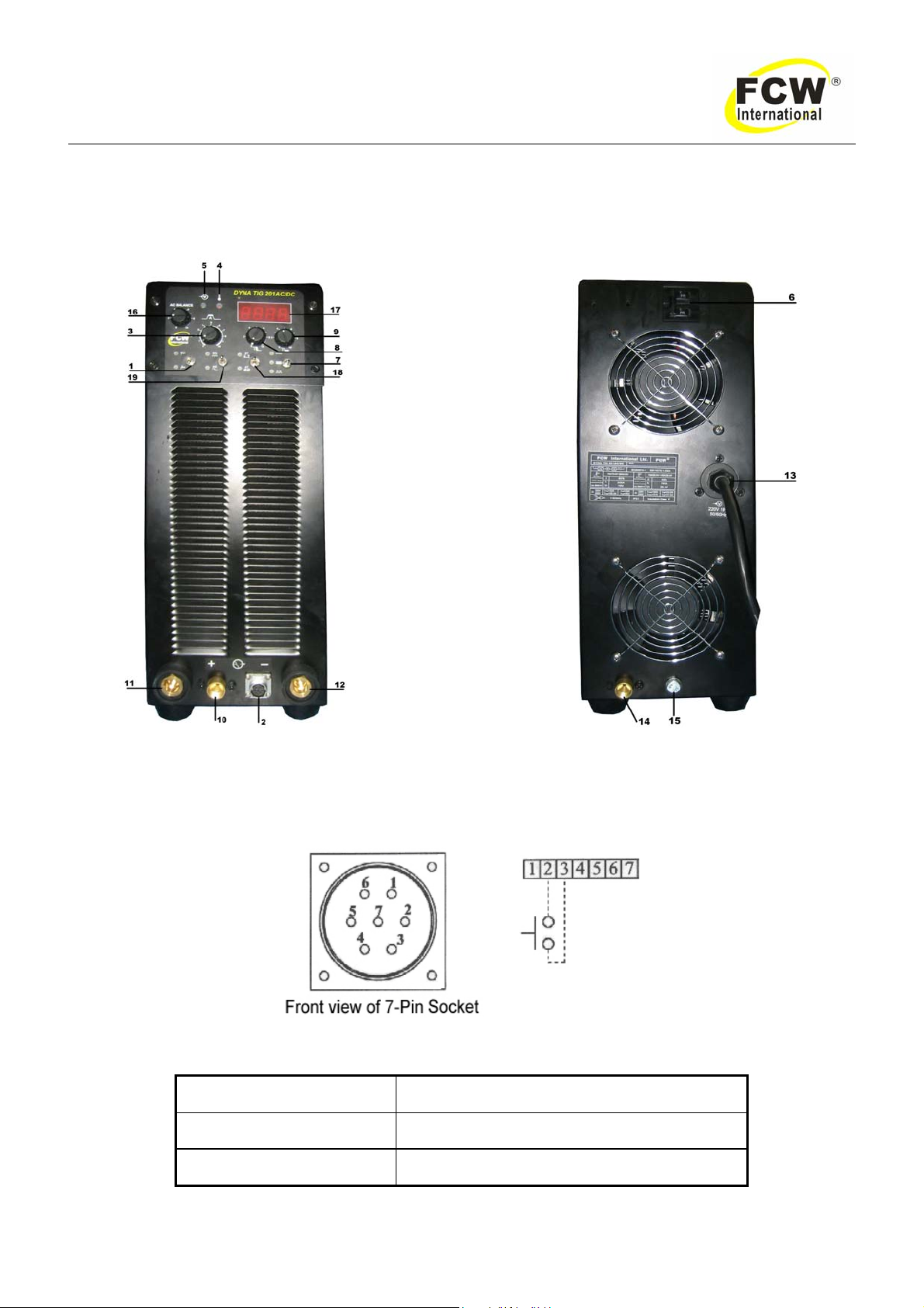
DYNATIG 201AC/DC Operating Manual
3.0 OPERATOR CONTROLS
3.01 DYNA TIG 201AC/DC controls
Figure 2
1. Process Selection——Stick / HF TIG.
2. 7-Pin Socket——Used for the TIG torch switch only.
Figure 3
Pin Function
2 TIG torch switch
3 TIG torch switch
Table 4

- 12 -
DYNATIG 201AC/DC Operating Manual
3. Amperage Control——Selects the desired amperage within the entire range of the welding power
source.
4. Warning indicator——Activates under the following conditions:Input voltage is too low / too high /
Thermal overload.
5. AC Power indicator——Lights when in the ON position.
6. Main Power Switch——Switch to the ON position power source.
7. Pulse Switch:
DC only (no pulse).
High frequency pulse: the pulse frequency can output 250Hz.
Low frequency pulse: the pulse frequency can output 2Hz.
8. Down Slope Time Control.
9. Post Flow Time Control.
10. Gas Outlet.
11. Positive (+) Socket——TIG connect the work lead/ MMA connect the electrode holder.
12. Negative (-) Socket——TIG connect the TIG torch/ MMAconnect the work lea.
13. Input Power Cable——3 meter.
14. Input Gas Fitting——Size 5/8”-18RH female.
15. Ground screw——Ground cable.
16. AC Balance.
17. Digital display——Display welding current.
18. Control Selection——2T/4T Function.
19. Control Selection——AC/DC Function.
WARNING
When the welder is connected to the primary supply voltage, the internal electrical
components maybe at primary potential with respect to earth.
- 13 -
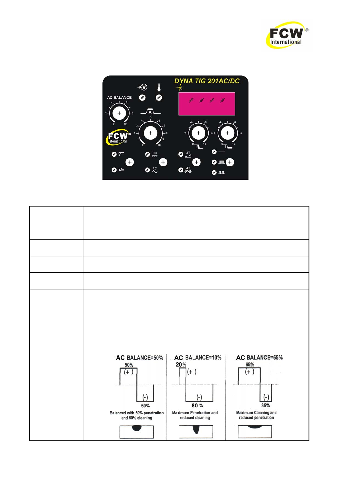
DYNATIG 201AC/DC Operating Manual
3.02 Weld parameters description
Figure 4 DYNA TIG 201AC/DC front panel with parameter description
Parameter Description
Peak Current This parameter sets the peak current when in pulse mode.
Welding Current This parameter sets the welding current when pulse is off.
Base Current When choice pulse mode this base current by the welding machine in the automatic
hypothesis is 10A.
Pulse Width When choice pulse mode this pulse width is fixed.
Pulse Freq. When choice pulse mode this pulse frequency from 2Hz to 250Hz depend on peak
current.
AC Balance
This parameter is used for aluminium AC TIG mode and is used to set the
penetration to cleaning action for the AC weld current. Generally AC BALANCE is
set to 50% for AC STICK welding . The AC BALANCE control changes the ratio of
penetration to cleaning action of the AC TIG welding arc.Maximum weld penetration
is achieved when the AC BALANCE control is set to 10%.Maximum cleaning of
heavily oxidised aluminium or magnesium alloys is achieved when the AC
BALANCE control is set to 65%.

- 14 -
DYNATIG 201AC/DC Operating Manual
Down Slope Time This parameter operates in TIG modes only and is used to set the time for the
welding current to ramp down, this control is used to eliminate the crater that can
form at the completion of a weld.
Post-Flow
t2
This parameter operates in TIG modes only and is used to adjust the post gas flow
time once the arc has extinguished. This control is used to dramatically reduce
oxidation of the tungsten electrode.
Table 5 Weld parameter description for DYNA TIG series
3.03 Weld parameter for DYNA TIG 201AC/DC
Model DYNA TIG 201 AC/DC
Peak Current 10~200A
TIG 10~200A
Welding
Current STICK 10~160A
Pulse Frequency 2Hz/ 250Hz/ OFF
Down Slope Time 0~5S
Post-Flow Time 0~5S
AC Balance 20 to 80%
Table 6 Weld parameters for DYNA TIG 201AC/DC

- 15 -
DYNATIG 201AC/DC Operating Manual
4.0 SET-UP FOR MMA (STICK) AND GTAW (TIG)
Conventional operating procedures apply when using the welding power source, i.e. connect work lead
directly to work piece and welding cable is used to electrode holder. Wide safety margins provided by the coil
design ensure that the welding power source will withstand short-term overload without adverse effects. The
welding current range values should be used as a guide only. Current delivered to the arc is dependent on the
welding arc voltage, and as welding arc voltage varies between different classes of electrodes, welding
current at any one setting would vary according to the type of electrode in use. The operator should use the
welding current range values as a guide, and then finally adjust the current setting to suit the application.
Figure 5 Set up for DYNA TIG 201 AC/DC
WARNING:
Before connecting the work clamp to the work and inserting the electrode in the electrode holder
make sure the Primary power supply is switched off.
CAUTION 2:
Remove any packaging material prior to use. Do not block the air vents at the front or rear of the
Welding Power Source.
- 16 -
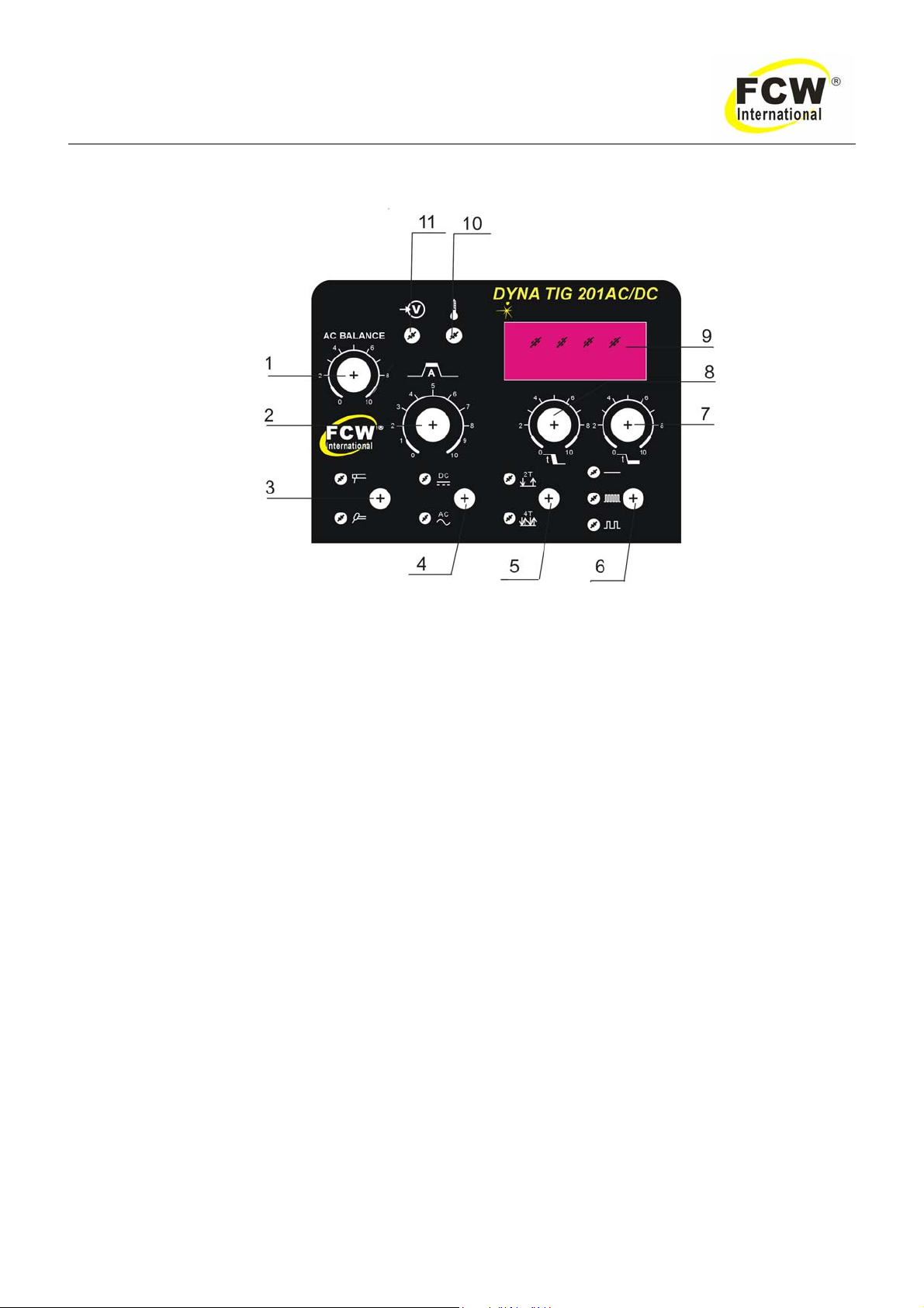
DYNATIG 201AC/DC Operating Manual
5.0 POWER SUPPLY CONTROLS INDICATORS AND REATURES
Figure 6 DYNA TIG 201AC/DC front panel
1. AC Balance.
2. Amperage Control——Selects the desired amperage within the entire range of the welding power
source.
3. Process Selection——Stick / HF TIG.
4. Control Selection——AC/DC Function.
5. Control Selection——2T/4T Function.
6. Pulse switch——Three kind of choices,from the top down in turn is:
High frequency pulse TIG welding: The pulse frequency may output the 250Hz.
Low frequency pulse TIG Welding: The pulse frequency may output the 2Hz.
DC only
7. Post flow time control.
8. Down slope time control.
9. Digital display——Display welding current.
10. Warning indicator——Activates under the following conditions:Input voltage is too low / too high /
Thermal overload.
11. AC Power indicator——Lights when in the ON position.

- 17 -
DYNATIG 201AC/DC Operating Manual
5.01 Stick welding
zConnect work lead to negative terminal.
zConnect electrode lead to positive terminal.
zSwitch machine on.
zSet MMA mode.
zSet welding current control (see table 7).
Workpiece thickness mm 0.5-2.0 2.0-5.0 5.0-7.0
Electrode diameter mm 1.0-2.0 2.0-3.2 3.2-4.0
Welding current(A)10-50 50-150 150-250
Table 7
5.02 DC TIG welding
zConnect work lead to positive terminal.
zConnect TIG torch to negative terminal.
zSwitch machine on.
zSet DC TIG mode.
zSet welding current control (see table 8).
5.03 AC TIG welding
zConnect work lead to positive terminal.
zConnect TIG torch to negative terminal.
zSwitch machine on.
zSet AC TIG mode.
zSet welding current control (see table 9).
5.04 DC pulse TIG welding
zConnect work lead to positive terminal.
zConnect TIG torch to negative terminal.
zSwitch machine on.
zSet DC TIG mode.
zSet pulse high/ pulse low position.
zSet welding current control (see table 8).

- 18 -
DYNATIG 201AC/DC Operating Manual
5.05 AC pulse TIG welding
zConnect work lead to positive terminal.
zConnect TIG torch to negative terminal.
zSwitch machine on.
zSet AC TIG mode.
zSet pulse high/ pulse low position.
zSet welding current control (see table 9).
Workpiece
thickness (mm) Tungsten
diameter (mm) Welding current
(A) Filler wire
diameter (mm) Argon Gas flow
(L/min)
0.3-0.5 1-1.6 5-30 3-8
0.5-1.2 1.6-2 10-50 1.2-1.6 4-8
1.2-2 1.6-2 10-50 1.2-1.6 4-8
1.2-2 1.6-2 30-70 1.6-2.0 6-9
2-4 2-4 60-100 1.6-2.0 7-10
4-6 3-4 100-200 2.0-2.5 10-15
Table 8
Workpiece
thickness (mm) Tungsten
diameter (mm) Welding current
(A) Filler wire
diameter (mm) Argon Gas flow
(L/min)
1-1.5 1.6 60-80 0.8-1.0 5-10
1.5-2 2.4 125-145 1.0-1.6 8-10
2-3 3.2 125-160 1.6-2.4 8-10
3-4 4.0 140-200 2.4-3.2 10-15
4-6 4.8 180-240 3.2-4.0 10-15
6-10 6.4 240-320 4.0-4.8 10-15
Table 9

- 19 -
DYNATIG 201AC/DC Operating Manual
6.0 BASIC TIG WELDING GUIDE
6.01 Electrode Polarity
Connect the TIG torch to the - / torch terminal and the work lead to the + / work terminal for direct
current straight polarity. Direct current straight polarity is the most widely used polarity for DC TIG
welding. It allows limited wear of the electrode since 70% of the heat is concentrated at the work piece.
6.02 Tungsten Electrode Current Ranges
Electrode Diameter (mm) DC current (A) AC current (A)
1.0 30—60 30—70
1.6 60—115 60—95
2.4 100—165 125—150
3.2 135—200 130—225
4.0 190—280 190—280
4.8 250—340 250—340
Table 10 Current ranges for varies tungsten electrode sizes
6.03 Tungsten Electrode Types
Tungsten type
(Ground finish) Welding Application Features Color
code
Thoriated 2% DC welding of mild steel, stainless steel
and copper Excellent arc starting, Long life, high
current carrying capacity Red
Zirconated 1% High quality AC welding of aluminium,
magnesium and their alloys.
Self cleaning ,Long life, Maintains
balled end, High current carrying
capacity. White
Ceriated 2% DC welding of mild steel, stainless steel,
copper, aluminium, magnesium and their
alloys
Longer Life, More stable arc, Easier
starting, Wider current range,
Narrower more concentrated arc Grey
Table 11 Tungsten electrode types

- 20 -
DYNATIG 201AC/DC Operating Manual
6.04 Guide for Selecting Filler Wire Diameter
Filler wire diameter DC current range (Amps) AC current range (Amps)
1.6 20—90 30—95
2.4 65—115 125—160
3.2 100—165 180—240
4.8 200—350 220—320
Table 12 Filler wire selection guide
Notice
:
The filler wire diameter specified in Table 11 is a guide only, other diameter wires may be used according to the welding
application.
6.05 Shielding gas selection
Alloy Shielding gas
Aluminium & alloys Argon
Carbon steel Argon
Stainless steel Argon
Nickel alloy Argon
Copper Argon
Titanium Argon
Table 13 Shield gas selection
Table of contents
Other FCW Welding System manuals


Popular Welding System manuals by other brands

ESAB
ESAB MIG 301i instruction manual

Hobart
Hobart Beta Mig 135 P owner's manual

Lincoln Electric
Lincoln Electric Stick Electrode Welding C2.410 Guide

Leister
Leister VARIMAT V2 Series operating instructions

Migatronic
Migatronic 200 DC HP PFC quick guide

Miller
Miller Cool Runner 3CS OM-230 161 F owner's manual


