FE M-UPS050AD2B User manual
USER’S MANUAL
Uninterruptible Power Supply
GX 200 Series
Model M-UPS050AD2B
M-UPS075AD2B
M-UPS100AD2B
INR
-
HG5687

For Safe Use
About handling of this manual
This manual describes important information for using this product safely. Please read
this manual carefully before using this product. Use this product, after reading and
understanding especially "Caution about Safety" and "Caution for Use" in this manual
well. Furthermore, this manual should be retained for future reference.
About “Use which Requires High Safety”
This product is designed and manufactured for the general use, such as general office use
and personal use, and is not designed and manufactured for uses (control of nuclear
reactions at the nuclear facilities, aircraft flight control, air traffic control, mass transport
control, medical life support systems, and missile launch control in weapon systems, etc.)
that require a high degree of safety, and can cause death or serious injury if the required
safety is not maintained. Do not use this product without carrying out measures to ensure
the required safety for such a use. If using this product for such a use, consult with our
sales representatives.
About Prevention of Radio Interference
Important
This product is class A information technology equipment based on the standard of
Voluntary Control Council for Interference by Information Technology Equipment
(VCCI). Using this product in a residential area may cause radio interference. In this
case, the user may be requested to take an appropriate measure.
About Prevention of Harmonic Current Interference
M-UPS050AD2B conforms to the Guideline of harmonic restraint measures for
general-purpose UPS.
M-UPS075AD2B and M-UPS100AD2B conform to IEC61000-3-12.
Do not reproduce or reprint this manual without notice.
All Rights Reserved, Copyright ○
cFuji Electric Co., Ltd. 2011


i
Introduction
An uninterruptible power supply is a device for supplying stable electric power to OA
devices, FA devices, and computer devices.
This manual describes installation, running, daily management, troubleshooting, and
maintenance of an uninterruptible power supply. Use an uninterruptible power supply
correctly in accordance with this manual.
In this manual, an uninterruptible power supply (this product) is described as UPS for
short.
Content and organization of this manual
The organization of this manual is as follows:
Caution about Safety and Caution for Use
The cautions about safety are described. If you use the UPS, be sure to read this
section.
1 Unpacking
The cautions about taking out the UPS from a box are described.
2 Outline
The name of each part and the operation mode of the UPS are described.
3 Installation
Installation of the UPS and connection of the cable are described.
4 Running
The methods of run and stop of the UPS are described.
5 Inspection
The cautions about daily inspection and rolling blackouts are described.
6 Troubleshooting
Troubleshooting is described.
7 Maintenance
Replacement of battery and cooling fan and method of storage of the UPS are
described.
8 Appendix
Rated specification and the cautions in UL standard are described.
Due to the purpose to use, the chapters which should be referred to especially are as
follows.
For installation personnel Caution about Safety, Caution for Use,
Chapters 1, 2, 3, and 4
For users Caution about Safety, Caution for Use,
Chapters 2, 4, 5, and 6
For maintenance personnel Caution about Safety, Caution for Use,
Chapters 2, 4, 5, and 7

Introduction
ii
About warning display
In this manual, the following warning displays are described so that user or the people
around the UPS do not suffer damage to the body and property.
Warning
"Warning" indicates that death or serious injury may result, if the
UPS is not used correctly.
"Caution" indicates that slight or moderate injury may result or
the UPS or user’s property may be damaged, if the UPS is not
used correctly.
Important "Important" indicates caution about the use of the UPS.
About marks in this manual
Marks in this manual have the following meanings:
The state of the UPS is described.
Have a look if necessary. How to deal with, the reference place,
etc. are described.
About symbols of LED
The states of LED are indicated by the following symbols:
: Lighting
: Blinking
: Not lighting
Attention
Information in this manual is subject to change without notice.
Caution

iii
Caution about Safety
List of important warnings
The important warnings described in this manual are as follows.
"Warning" indicates that death or serious injury may result, if the
UPS is not used correctly.
Electric shock
Do not remove the cover of the UPS.
Since there are some portions with high voltage in the inside of the
UPS, there is fear of an electric shock.
"Caution" indicates that slight or moderate injury may result or
the UPS or user’s property may be damaged, if the UPS is not
used correctly.
Put neither a stick nor a finger into the cooling fan or the
vent hole.
Electric shock
Injury There is fear of an electric shock or an injury.
Electric shock
Perform the battery and cooling fan replacement by
maintenance personnel.
There is fear of an electric shock.
The UPS should be connected to ground. (more than
class D grounding)
When connecting to an input power supply, connect the
grounding wire to the ground terminal.
There is fear of an electric shock.
Electric shock
Failure When connecting the UPS to an input power supply,
connect the electric wire of hot-line side to the AC input
terminals L1/R and L2/S, and connect the grounding wire
to the input ground terminal. Likewise, in the connections
between the output of the UPS and the connection device,
connect the electric wire of hot-line side to the AC output
terminals l1/U and l2/V, and connect the grounding wire to
the output ground terminal.
If connected by mistake, there is fear of the malfunction by noise,
the failure, or an electric shock.
When inspecting or maintaining the connection device (a
device getting connected to the UPS) or the UPS, turn off
power of the connection device and stop the operation of
UPS. And turn off the breaker of the distribution board
and cut off connection of AC input terminal.
There is fear of an electric shock.
Warning
Caution

Caution about Safety
iv
Injury Do not ride on or put an object on the UPS.
There is fear of an injury or an overturn.
The UPS is heavy. Pay enough attention to handling the
UPS.
Injury
Damage
Take out the UPS in a level and flat place. If you lift the UPS alone
or carry it, there is fear of hurting arms, legs or hip, or dropping the
UPS. Work by a suitable number of persons. And pay enough
attention to prevent an accident such as an overturn or a drop. The
weight of the UPS is as follows:
M-UPS050AD2B : 63kg (without battery : 29kg)
M-UPS075AD2B : 127kg (without battery : 59kg)
M-UPS100AD2B : 127kg (without battery : 59kg)
This UPS can be installed laying down. If installing laying
the UPS down, tilt it only to the right side, seeing from the
front. Never tilt the UPS to the left side.
Fire
Damage
If tilting the UPS to the left side, the liquid leak of a battery may
occur, there is fear of a fire or the UPS failure in the case. If
installing laying the UPS down, be sure to tilt it to the right side.

Caution about Safety
v
Damage Do not use the UPS for the uses that may hurt the human
body or exert an important influence on the society and
public.
Medical instrument affecting human life directly
Device that may hurt the human body
Socially and publicly important computer system
Do not put an object (display or floppy disk etc.)
vulnerable to magnetism around the UPS.
There is fear of exerting a bad influence on the object.
Confirm that the voltage set up by the switch of voltage
setting is within the range of input voltage of the
connection device.
There is fear of damaging the connection device.
Do not operate the switch of voltage setting during
operation of the UPS.
There is fear of damaging the connection device, since the changed
voltage is outputted at the restart. And even if operating the switch
during operation of the UPS, the output voltage cannot be changed.
Replace the battery periodically.
If continuing to use the UPS that the battery life ended, there is fear
of a liquid leak of battery, a smoking, and an ignition.
Replace the battery with one specified by our company
and a new one.
If using the un-specified battery or mixing an old battery and a new
battery, it becomes the cause of a liquid leak of battery, a smoking,
an ignition, and the UPS failure and trouble.
When performing the rolling blackouts or when cutting off
an input power supply, perform them after stopping the
operation of the UPS, with reference to Chapter 4.2
"Turning off the UPS". The stop of operation can be
confirmed by slow blink (in the cycles of approximately
1.6 sec.) of the RUN LED (green).
If cutting off an input power supply when the UPS is operating (the
RUN LED is lighting), the UPS switches to the battery operation
since it will be in the same state as a power failure.
Performing such unnecessary battery operation leads to a shortening
of a cycle of battery replacement.
Warning label
Warning labels are attached to the UPS.
Never remove the labels.

vi
Caution for Use
Be careful about the following when using the UPS.
Important "Important" indicates caution about the use of the UPS.
Do not install and store the UPS in the following places:
In an outdoor location
A place exposed to the elements
An extremely humid place and a dusty place
A place with corrosive gas or salinity
A place subjected to direct sunlight
A place near sparks or heating element
An extremely hot or cold place or place where the temperature fluctuates
greatly
A place where vibration and a shock are added
Do not perform the battery check in succession.
When the battery check is performed, the UPS temporarily switches to the battery
operation.
If the battery check is performed in succession, there is fear of the battery deterioration
or a shortening of a cycle of battery replacement since the battery becomes an
over-discharge state.
If the UPS is not used for a long time, charge the battery every two
months.
The battery is charged by operating the UPS.
For the battery charging time, refer to Chapter 8.1 "Rated Specification".
If the UPS is left without operating for a long time, there is a possibility that the UPS get
unusable since the battery becomes an over-discharge state due to self-discharge.
This UPS is recyclable.
This UPS uses the small sealed lead storage battery. The small sealed lead storage
battery uses expensive and rare resources. However, these precious resources are able to
recycle. Cooperate in recycling without disposing of the used battery.
Do not block the vent hole and cooling fan or use the UPS in a stuffy place.
The vent hole and cooling fan are equipped in order to cool the inside of the UPS.
There is a possibility that the inside and ambient temperature of the UPS may get out of
the rated specification.
Replace the cooling fan periodically.
If continuing to use the UPS that the cooling fan life ended, there is a possibility that the
inside temperature of the UPS may get out of the rated specification.
Do not use 5 to 9 of the switch of voltage setting.
It becomes impossible for the UPS to start up normally.

Caution for Use
vii
The permissible voltage between the input electric cable of the UPS and
the ground is 250V AC.
If the voltage more than 250V AC is applied, the filter circuit of the input part may be
damaged.
The permissible input surge voltage of the UPS is 5kV peak (1.2 50µs).
However, if the model of the UPS is "-UC" and "-C", it is 2kV peak (1.2
50µs).
If the surge voltage more than 5kV peak ("-UC" and "-C" are 2kV peak) is applied, the
filter circuit of the input part may be damaged.
The input voltage of the UPS is 160 to 288V AC.
When input voltage is different from the rated specification (400V AC etc.), install a
transformer at the outside of the UPS to convert voltage. If the voltage more than the
range of the input voltage is applied, the UPS may be damaged.
Pay attention to an input voltage.
This UPS can operate up to 288V AC. However, an input voltage of the general device is
200V AC ±10%. Therefore, if switching to the bypass operation when applying the
voltage of 220V AC to the UPS, the voltage exceeding specification is applied to the
connection device. Adjust the input voltage to the specification of connection device.
Do not apply single-line grounding on the output side.
Between the input and output of the UPS is not insulated. Therefore, do not apply
single-line grounding on the output side.
There is fear of becoming the cause of the trouble of connection device by noise or the
failure.
When connecting the UPS to the electrical power equipment with the earth
leakage breaker, select the earth leakage breaker not to trip due to current
leakage.
When connecting the UPS to the electrical power equipment with the earth leakage
breaker, select the earth leakage breaker in consideration of total number of current
leakage of the UPS plus current leakage of the connection device.
When connecting the UPS to a three-phase power supply system, be sure
to connect the grounding phase of the three-phase power supply system
to the electrode of a grounding side of the AC input of the UPS.
If connecting to an un-grounding power supply, there is fear of becoming the cause of
the malfunction.
Caution for Use
viii
When using a generator temporarily during the rolling blackouts, use a
generator satisfying the following specification.
If connecting a generator not satisfying the following specification to the input part of
the UPS, there is a possibility of becoming the cause of the malfunction or damage of the
UPS.
Voltage regulation: depend on the input specification of the connection device
Frequency variation: within rated frequency ± 5% (frequency does not change
rapidly)
Voltage waveform distortion: within 5%
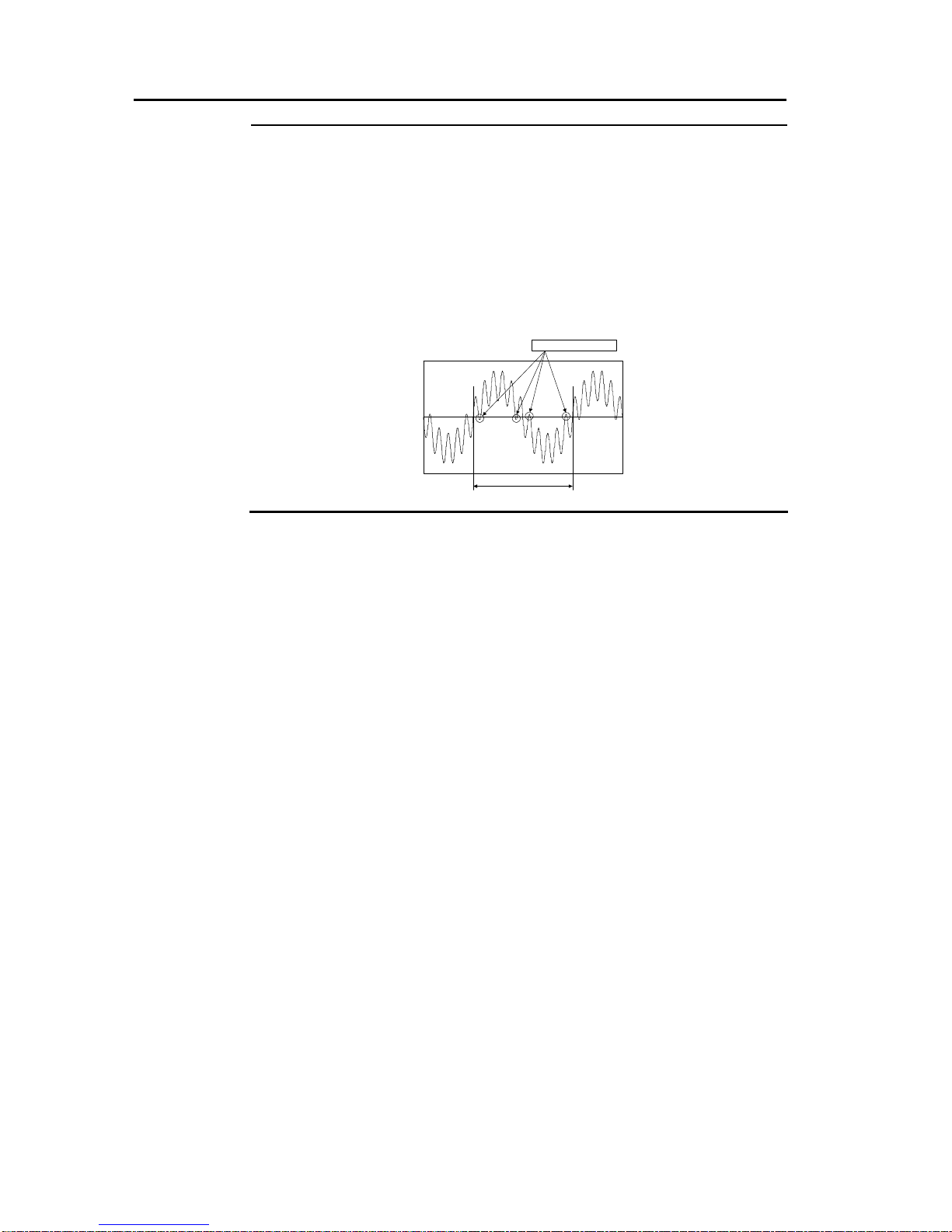
Voltage zero-cross condition: Zero-cross must not occur twice or more in 1
cycle.
50Hzor60Hz
Illegalzerocross

ix
Index
Introduction.......................................................................................................i
Caution about Safety .....................................................................................iii
Caution for Use..............................................................................................vii
1 Unpacking
1.1 Opening the Packing ...........................................................................1
Opening the packing
Confirming the contents of the packing
2 Outline
2.1 Name and Main Function of Each Part ...............................................2
2.2 Mechanism of the UPS.........................................................................5
At the normal operation
At the battery operation (In the event of an input power failure)
At the automatic bypass operation
At the manual bypass operation
3 Installation
3.1 Installing the UPS.................................................................................7
Caution about installation
Determining an installation location
Determining the installation method
Installation method
3.2 Connecting the Cable........................................................................12
Caution about connecting the cable
Preparation before connecting the cable
Connecting the output cable
Connecting the input cable
3.3 Interface Port......................................................................................16
CN1 (No-voltage contact signal interface)
CN2 (RS-232C interface)
3.4 Setting up the Output Voltage...........................................................18
The setup procedures of the rated output voltage
4 Running
4.1 Turning on the UPS............................................................................20
Confirming cable connection
Turning on the UPS
Turning on the connection device
4.2 Turning off the UPS............................................................................23
Turning off the connection device
Turning off the UPS
5 Inspection
5.1 Care and Daily Inspection .................................................................25
How to care for the UPS
Daily inspection

x
5.2 Caution and Measures for the Rolling Blackouts.............................27
Operation before the rolling blackouts
Operation after the rolling blackouts
5.3 Inspecting the Battery (Battery Check).............................................29
Confirming the state of the UPS
Using the manual check function
Charging the battery
6 Troubleshooting
6.1 If a Warning Beep Sounds.................................................................34
6.2 Operation Mode List...........................................................................35
Types of blink of LED
Types of warning beep
Operation mode list
7 Maintenance
Replacing the Battery ........................................................................40
Timing of the battery replacement
The method of battery replacement
Disposal and storage of battery
7.2 Replacing the Cooling Fan ................................................................43
Timing of the cooling fan replacement
The method of cooling fan replacement
7.3 When Not Using the UPS (Storage)...................................................45
Work before storage
If a storage period exceeds two months
8 Appendix
8.1 Rated Specification............................................................................46
8.2 Additional Description for UL Type...................................................48

- 1 -
1Unpacking
1.1 Opening the Packing
Opening the packing
The UPS is heavy. Pay enough attention to handling the UPS.
Injury
Damage
Take out the UPS in a level and flat place. If you lift the UPS alone or
carry it, there is fear of hurting arms, legs or hip, or dropping the UPS.
Work by a suitable number of persons. And pay enough attention to
prevent an accident such as an overturn or a drop. The weight of the UPS
is as follows:
M-UPS050AD2B : 63kg (without battery: 29kg)
M-UPS075AD2B : 127kg (without battery: 59kg)
M-UPS100AD2B : 127kg (without battery: 59kg)
1. Open the packing box and take out the UPS.
Confirming the contents of the packing
2. Confirm that there is no damage in the appearance of the UPS.
3. Confirm that all accessories are contained.
UPS model Accessories No. of pcs
M-UPS050AD2B
(5kVA)
User’s manual (this document)
Guarantee (this document)
Stabilizer (with 6 setscrews)
1 copy
1set
M-UPS075AD2B
(7.5kVA)
User’s manual (this document)
Guarantee (this document)
Stabilizer (with 6 setscrews)
1 copy
1set
M-UPS100AD2B
(10kVA)
User’s manual (this document)
Guarantee (this document)
Stabilizer (with 6 setscrews)
1 copy
1set
If the UPS got damaged, or accessories are missing:
Contact an agent from which you purchased the UPS.
Caution

- 2 -
2Outline
2.1 Name and Main Function of Each Part
This chapter describes the name and main function of each part of the UPS.
〈M-UPS050AD2B〉
RUN
ALARM
OVERLOAD
BYPASS
BATTERY
CONDITION
RESET
UPS
BATT
CHECK
(9)
(11)
(16)
(13)
(14)
(15)
(10)
(18)
(12)
(1)
(2)
(3)
(4)
(5)
(6)
(7)
(8)
(19)
(17)

2.1 Name and Main Function of Each Part
- 3 -
〈M-UPS075AD2B, M-UPS100AD2B〉
(1)
(2)
(3)
(4)
(5)
(6)
(7)
(8)
(10)
(17)
(9)
(11)
(12)
(13)
(14)
(15)
(18)
(19)
(16)

2Outline
- 4 -
Name Main function
(1)
RUN It lights up (green) while the UPS is operating normally.
(2)
ALARM It lights up (orange) when the abnormalities occurred inside the
UPS.
(3)
OVER LOAD It lights up (orange) when the load capacity of the connection
device exceeded the rated specification.
(4)
BYPASS It lights up (orange) while the UPS is performing the bypass
operation.
(5)
LED
BATTERY
CONDITION
When the battery is normal, it indicates the amount of battery
charge according to the sort of lighting (green).
(Not lighting:0 to 50%, Blinking:50 to 80%, Lighting:80 to 100%)
When the battery is abnormal, it lights up (orange).
(6)
RUN/STOP It is the switch for performing operation and stop of the UPS.
RUN and STOP are switched every time this switch is pressed for
approximately 1 second.
(7)
RESET Press this switch when stopping the warning beep. Also, if this
switch is pressed for approximately 3 seconds after the failure is
restored, theALARM LED goes out.
(8)
BATT CHECK It is the switch for performing the battery check manually. By
pressing the switch for approximately 2 seconds, the battery check
is performed.
Switch
BYPASS
Press switch (7) and (8) for approximately 3 seconds
simultaneously when switching to the bypass operation forcibly
(manually) while the UPS is operating normally. When the
switches are pressed for approximately 3 seconds simultaneously
again, the UPS returns to the normal operation.
(9)
Vent hole (cooling fan) The inside of the UPS is ventilated and cooled. The direction of air
is intake.
(10)
Cooling fan The inside of the UPS is cooled. The direction of air is exhaust.
(11)
Input terminal block Connect to an input power supply.
(12)
Input breaker It is the breaker for protecting the input circuit.
(13)
Output terminal block Connect to an output system.
(14)
Ground terminal Connect a grounding wire.
(15)
Switch of voltage setting Set up the output voltage.
(16)
Dummy board Mount various option outlets. (-U, -UC type is no option)
(17)
Interface slot Mount various interface cards.
(18)
Contact signal (CN1) Output a no-voltage contact signal.
(19)
RS-232C (CN2) It is RS-232C interface.

2.2 Mechanism of the UPS
- 5 -
2.2 Mechanism of the UPS
At the normal operation
While the UPS is operating normally, the UPS operates an AC power supply as an
input, and supplies the output of constant voltage to connection device. Simultaneously,
the UPS charges an internal battery and prepares for the battery operation.
Output frequency synchronizes with input frequency.
+
Bypass
AC/ACconverter
Boostchopper
BatteryCharger
[UPS]
Toconnectiondevice
:Powerisfed
:Powerisnotfed
Output
Inputpowersupply
Electricity flow during normal operation
At the battery operation (In the event of an input power failure)
When the power failure or the abnormalities of voltage or frequency of an input power
supply occur while the UPS is operating, the UPS starts the electric discharge from the
battery, and continues to supply the stable electric power to the connection device. In
addition, the changeover to the battery operation is performed without instantaneous
power interruption.
If the input power supply returns (the voltage of the input power supply returns within
the rated specification), the UPS will return to the above normal operation automatically.
+
Bypass
AC/ACconverter
Boostchopper
BatteryCharger
[UPS]
Toconnectiondevice
:Powerisfed
Theabnormalities
occurataninput
powersupply. WhiletheUPSisoperating,
-Powerfailure
-Theabnormalitiesofvoltageorfrequency
etc.
:Powerisnotfed
Output
Electricity flow during battery operation

2Outline
- 6 -
At the automatic bypass operation
When the abnormalities occurred in the UPS during the normal operation, the UPS
switches to the bypass operation automatically. During the bypass operation, the UPS
sends the input voltage to the output directly and supplies the electric power to the
connection device. In this operation state, even if the power failure occurs, the UPS
becomes the power failure state without switching to the battery operation.
+
Bypass
AC/ACconverter
Boostchopper
BatteryCharger
[UPS]
Toconnectiondevice
:Powerisfed
Anerror
occursinside
theUPS
-TheabnormalitiesinsidetheUPS
:Powerisnotfed
Output
Inputpowersupply
Electricity flow during automatic bypass operation
At the manual bypass operation
It is possible to switch to the bypass operation manually during the normal operation.
Press the RESET switch and the BYPASS switch for approximately 3 seconds
simultaneously to switch to the bypass operation.
When the switches are pressed for approximately 3 seconds simultaneously again, the
UPS returns to the normal operation. In this operation state, even if the power failure
occurs, the UPS becomes the power failure state without switching to the battery
operation.
+
Bypass
AC/ACconverter
Boostchopper
BatteryCharger
[UPS]
Toconnectiondevice
:Powerisfed
:Powerisnotfed
Output
Inputpowersupply Switchingtothebypass
operationmanually
Electricity flow during manual bypass operation

- 7 -
3Installation
3.1 Installing the UPS
Caution about installation
Injury Do not ride on or put an object on the UPS.
There is fear of an injury or an overturn.
Damage Do not put an object (display or floppy disk etc.) vulnerable to
magnetism around the UPS.
There is fear of exerting a bad influence on the object.
Determining an installation location
Important
Do not install the UPS in the following places:
In an outdoor location
A place exposed to the elements
An extremely humid place and a dusty place
A place with corrosive gas or salinity
A place subjected to direct sunlight
A place near sparks or heating element
An extremely hot or cold place or place where the temperature fluctuates
greatly
A place where vibration and a shock are added
Do not use the UPS in a residential area or its adjacent area.
This UPS is class A information technology equipment based on the standard of
Voluntary Control Council for Interference by Information Technology Equipment
(VCCI). Using this UPS in a residential area may cause radio interference. In this case,
the user may be requested to take an appropriate measure.
Do not block the vent hole and cooling fan or use the UPS in a stuffy
place.
The vent hole and cooling fan are equipped in order to cool the inside of the UPS.
There is a possibility that the inside and ambient temperature of the UPS may get out
of the rated specification.
Caution
This manual suits for next models
2
Table of contents
Other FE UPS manuals


