FEB 860 Series User manual
IOM-F -860_860U
INSTALLATION, OPERATION, MAINTENANCE
Maintenance Manual
Series 860 Reduced Pressure Zone Assemblies
Models 860, LF860, 860U & LF860U
1/2"- 2" (15 – 50mm)
Read and understand this manual prior to installing,
operating or servicing this equipment.
Series 860
Table of Contents
Feature and Operating Procedures................................ 2
Vandalism.................................................... 2
General Service Procedures ..................................... 3
Cut-A-Way Drawing ............................................ 3
Troubleshooting Guide ......................................... 4
Check Module Disassembly ..................................... 6
Check Module Seal Replacement................................. 6
Check Module Re-Assembly..................................... 7
Relief Valve Repair............................................. 7
Testing ...................................................... 9
Air Gap Drain Installation Instructions.............................. 9
Exploded View ............................................... 10
Parts List ................................................... 10
Repair Kits .................................................. 11
Freeze Protection............................................. 11
Main Valve Draining Procedure (1/2" - 2")........................... 11
Warranty.................................................... 12
WARNING
!
Read this Manual BEFORE using this equipment.
Failure to read and follow all safety and use information
can result in death, serious personal injury, property
damage, or damage to the equipment.
Keep this Manual for future reference.
NOTICE
If the unit is installed where a protective device is recommended may be
a problem, the assembly should be protected and secured. On 1/2" through
2" (15 – 50mm) units the handles of shutoff valves can be removed to
discourage tampering. A protective enclosure can be installed over the unit
to discourage vandals. If an enclosure is used, it should be installed so that
adequate clearance is available for maintenance and testing. Consult local
codes before installing any type of protective enclosure.

2
Feature and Operating Procedures
MAINTENANCE MANUAL: MODELS 860, LF860, 860U & LF860U 1/2"- 2" (15 – 50mm)
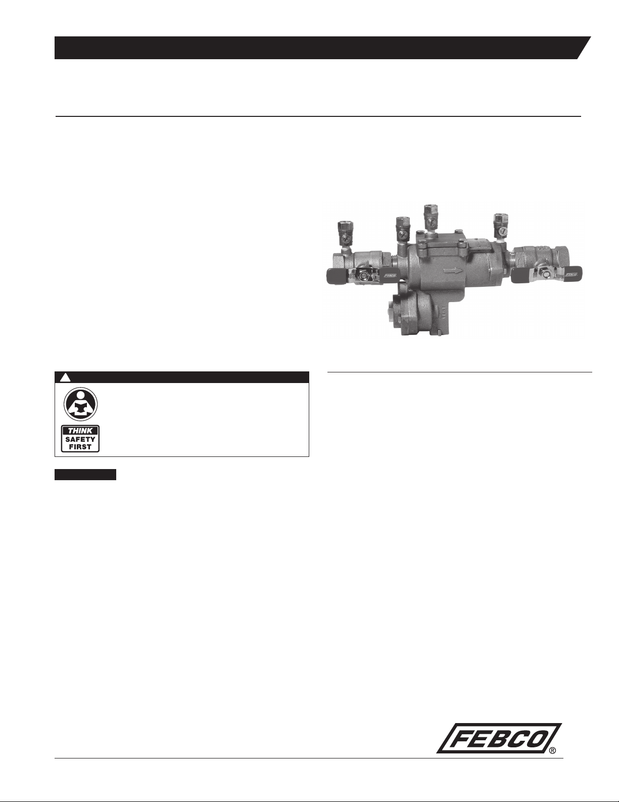
The FEBCO Series 860 Reduced Pressure Zone Backflow Preventer
Assembly consists of two independently operating, spring loaded check
valves with a pressure differential relief valve located between the two
checks. The pressure drop across the first check valve is approximately
7.0 psid with no flow. The relief valve consists of a hydraulically balanced
diaphragm with the high pressure side hydraulically connected to the
upstream pressure zone. The relief valve remains closed during normal
operation. The low pressure side of the diaphragm is spring loaded to
force the relief valve to open when the pressure drop the first check and
the diaphragm is reduced to approximately 3.0 psid. A complete assembly
includes two shutoff valves and four test cocks.
IMPORTANT: You are required to thoroughly read all installa-
tion instructions and product safety information before begin-
ning the installation of this product. FAILURE TO COMPLY
WITH PROPER INSTALLATION AND MAINTENANCE
INSTRUCTIONS COULD RESULT IN PRODUCT FAILURE
WHICH CAN CAUSE PROPERTY DAMAGE, PERSONAL
INJURY AND/OR DEATH. FEBCO is not responsible for dam-
ages resulting from improper installation and/or maintenance.
Local building or plumbing codes may require modifications to
the information provided. You are required to consult the local
building and plumbing codes prior to installation. If this informa-
tion is not consistent with local building or plumbing codes, the
local codes should be followed.
Need for Periodic Inspection/Maintenance: This product
must be tested periodically in compliance with local codes, but
at least once per year or more as service conditions warrant.
Replace internal components every 5 years.
Corrosive water conditions, and/or unauthorized adjustments
or repair could render the product ineffective for the service
intended. Regular checking and cleaning of the product’s inter-
nal components helps assure maximum life and proper product
function.
WARNING
!
3
General Service Procedures
MAINTENANCE MANUAL: MODELS 860, LF860, 860U & LF860U 1/2"- 2" (15 – 50mm)
1. FEBCO backflow prevention assemblies can be serviced with stan-
dard tools and are designed for ease of maintenance. The assemblies
are designed to be serviced in line, so the unit does not need to be
removed from the line during servicing. NO special tools are required.
Suggested Tool Kit Series 860 1/2"- 2"(15 - 50mm)
•1crescentwrench
•1mediumstandardscrewdriver
•Differentialpressuretestkit
•1mediumPhillipsscrewdriver
•Box/openendwrench
2. The most common cause of check fouling and relief valve discharge is
dirt and debris in the seating areas. The line should be flushed clean of
debris before installation of the assembly. To flush the line after instal-
lation of the assembly, slowly close the inlet shutoff valve, remove the
cover and spring assemblies of both check valves and open the inlet
shutoff valve to allow sufficient flow of water through the assembly to
clear all sand, debris, etc. from the line. If debris in the water continues
to cause fouling, a strainer may be installed upstream of the assembly
(check local codes).
3. Rinse all parts with clean water before reassembly.
4. Carefully inspect diaphragms, seals, and seating surfaces for damage
or debris. If the check valve seat disc has been severely cut at the seat
ring diameter, the assembly has been subjected to extremely high and
repeated back pressure. Either thermal water expansion or water
hammer are the most likely causes. If back pressure persists, consider
installation of a pressure relief valve downstream of the assembly.
5. Use caution to avoid damaging any guiding surfaces while handling
parts. Do not force parts together. The O-ring seals used in FEBCO
assemblies require only a small tightening force to ensure
a positive seal.
6. Test unit after servicing in accordance with locally approved test
methods to ensure proper operation (See page 9 for more details).
7. Refer to applicable exploded drawings and parts lists (pages 10-11)
for visual aid information.
8. Apply a thin coating of the lubricant supplied in the repair kit to the
O-rings and other seals as directed in this manual. Use of additional
lubricants must be FDA approved food grade petroleum jelly.
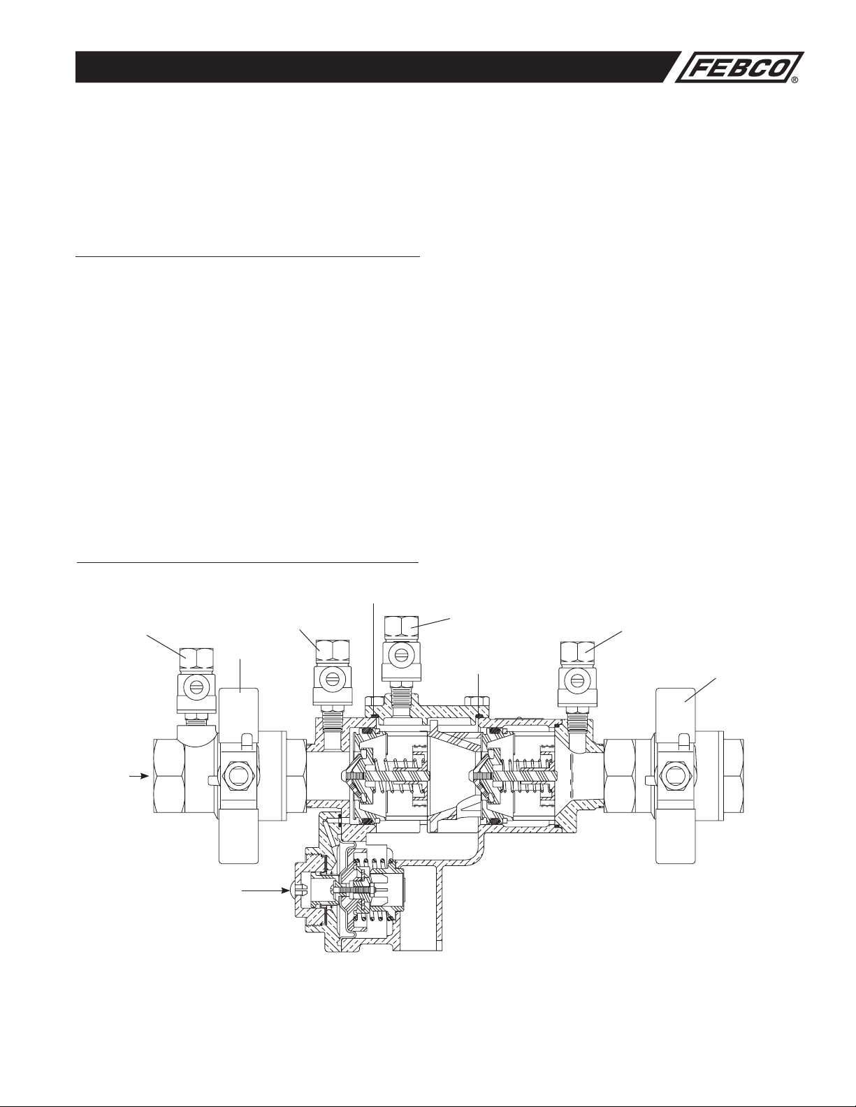
Test Cock #3
Test Cock #4
2nd Check Module
Relief Valve
Test Cock #1
Inlet Shutoff
Valve Outlet Shutoff
Valve
1st Check Module
Flow
Test Cock #2
Note: Union Ball Valves Not Shown
Cut-A-Way Drawing
4
MAINTENANCE MANUAL: MODELS 860, LF860, 860U & LF860U 1/2"- 2" (15 – 50mm)
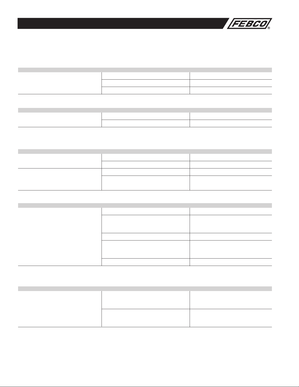
Troubleshooting Guide
With Differential Pressure Gauge
SYMPTOM #1 READING PROBLEM:
Check Differential Across 2 to 3 psid Leak in #1 or #2 check valve
#1 Check Valve 6 to 8 psid and steady Malfunctioning pressure relief valve
2 to 7 psid and steady Inlet pressure fluctuating
SYMPTOM #2 READING PROBLEM:
Check Differential Across 2 to 3 psid #1 check valve held open
#1 Check Valve 6 to 8 psid and steady Malfunctioning pressure relief valve
SYMPTOM #1 CAUSE: SOLUTION:
Continuous discharge from relief valve during A. Debris fouling #1 check valve Inspect and clean
NO FLOW conditions (Discharge stops with B. Outlet pressure higher than Inspect and clean
water flow) inlet pressure and debris
With this symptom, the pressure drop across fouling #2 check valve
the #1 check valve would be C. Spring stem not moving freely Inspect for dirt or other foreign material
2 to 3 psid. If a flow of water (more
Inspect and replace. If necessary,
than discharge) is created through
D. Damaged seat or seat disc seat disc can be reversed in
the valve, the pressure drop should increase
1/2" through 2" sizes
to approximately 7psi
E. Leakage at check module O-ring Inspect and replace seal or O-ring
SYMPTOM #2 CAUSE: SOLUTION:
Intermittent discharge from relief A. Inlet line pressure variations Eliminate or reduce pressure variations by
valve during NO FLOW conditions. causing relief valve to discharge installing a soft seated, spring loaded check
With the symptom, the pressure drop across on upstream side of device
the #1 check valve would be varying from B. Pressure surges (water hammer) causing Eliminate or reduce pressure surges
about 2 to 7 psid relief valve to discharge
as pressure wave passes through the zone
Without Differential Pressure Gauge
SYMPTOM #1 AND #2 RESULT PROBLEM:
A) Close Gate Valve #2 If discharge stops Leak in #2 check valve
If discharge does not stop Go to "B"
B) Open #4 test cock to produce If discharge stops Leak in #1 check valve
a flow greater than differential If discharge does not stop Malfunctioning pressure relief valve
relief valve discharge

5
MAINTENANCE MANUAL: MODELS 860, LF860, 860U & LF860U 1/2"- 2" (15 – 50mm)
Troubleshooting Guide (Continued)
SYMPTOM #3 CAUSE: SOLUTION:
Continuous discharge from relief valve during A. Seat disc dislodged from cavity in Reposition disc in main stem cavity
FLOW and NO FLOW conditions the main stem. (This can be caused Repressurize system slowly
With this symptom, the pressure drop across by pressure surges during initial filling of
the #1 check valve would be system lines.)
7 psid or more at all times B. Debris fouling the relief valve seat Inspect and clean
C. Debris blocking the relief valve Inspect and clean
sensing passage
D. Dirt or scale jamming main stem Inspect and clean, or replace
E. Leakage at main stem Inspect and clean, or replace
SYMPTOM #4 CAUSE: SOLUTION:
Relief valve does not open above A. Outlet gate valve not closed completely Inspect and clean
2.0 psid during field testing B. Plugged low pressure hydraulic passage Inspect and clean
(from “ZONE” to inner diaphragm)
C. Improper alignment of internal parts during Reassemble
reassembly (causing high resistance to movement)
D. Jammed main stem due to debris Clean
Check for debris blocking gate valve
SYMPTOM #5 CAUSE: SOLUTION:
First check pressure drop is low A. Debris fouling first check seat Inspect and clean
(less than 5 psid) during field testing B. Debris fouling second seat with backpressure Inspect and clean
C. Inlet pressure variations causing Eliminate pressure variations
inaccurate gauge reading (see symptom #2A)
D. Damaged seat or seat disc Inspect and clean as required
E. Worn guide, bushing or stem Inspect and replace as required
SYMPTOM #6 CAUSE: SOLUTION:
Second check fails to hold back A. Outlet gate valve not closed completely Inspect and clean
pressure during field testing B. Debris fouling second check seat Inspect and clean
C. Damaged seat or seat disc Inspect and replace if required
D. Worn guide, bushing or stem Inspect and replace if required
Other manuals for 860 Series
1
This manual suits for next models
4
Table of contents
Other FEB Industrial Equipment manuals


