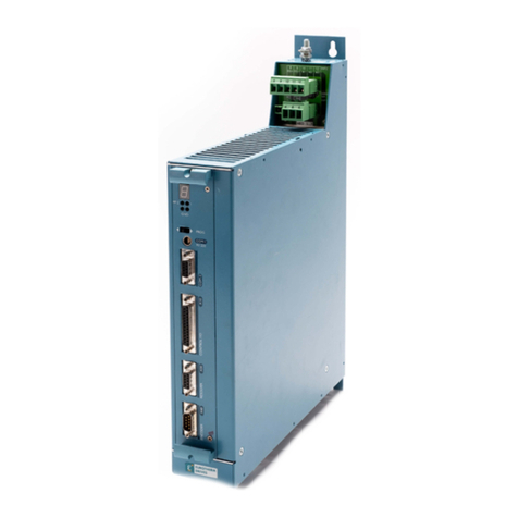
feedback MS150 User manual

MS150ModularServoWorkshop-ReferenceManual
33-008-2M5

MS150 Modular Servo Workshop
Reference Manual
33-008-2M5
Feedback
Feedback Instruments Ltd, Park Road, Crowborough, E. Sussex, TN6 2QR, UK.
Telephone: +44 (0) 1892 653322, Fax: +44 (0) 1892 663719.
Manual: 33-008-2M5 Ed01 980930
Printed in England by Fl Ltd, Crowborough
Feedback Part No. 1160–330082M5

Notes

MODULAR SERVO
Reference Manual Preface
33-008-2M5 i
THE HEALTH AND SAFETY AT WORK ACT 1974
We are required under the Health and Safety at Work Act 1974, to make available to users of this equipment certain information
regarding its safe use.
The equipment, when used in normal or prescribed applications within the parameters set for its mechanical and electrical
performance, should not cause any danger or hazard to health or safety if normal engineering practices are observed and they are used
in accordance with the instructions supplied.
If, in specific cases, circumstances exist in which a potential hazard may be brought about by careless or improper use, these will be
pointed out and the necessary precautions emphasised.
While we provide the fullest possible user information relating to the proper use of this equipment, if there is any doubt whatsoever
about any aspect, the user should contact the Product Safety Officer at Feedback Instruments Limited, Crowborough.
This equipment should not be used by inexperienced users unless they are under supervision.
We are required by European Directives to indicate on our equipment panels certain areas and warnings that require attention by the
user. These have been indicated in the specified way by yellow labels with black printing, the meaning of any labels that may be fixed to
the instrument are shown below:
CAUTION -
RISK OF
DANGER
CAUTION -
RISK OF
ELECTRIC SHOCK
CAUTION -
ELECTROSTATIC
SENSITIVE DEVICE
Refer to accompanying documents
PRODUCT IMPROVEMENTS
We maintain a policy of continuous product improvement by incorporating the latest developments and components into our equipment,
even up to the time of dispatch.
All major changes are incorporated into up-dated editions of our manuals and this manual was believed to be correct at the time of
printing. However, some product changes which do not affect the instructional capability of the equipment, may not be included until it is
necessary to incorporate other significant changes.
COMPONENT REPLACEMENT
Where components are of a ‘Safety Critical’ nature, i.e. all components involved with the supply or carrying of voltages at supply
potential or higher, these must be replaced with components of equal international safety approval in order to maintain full equipment
safety.
In order to maintain compliance with international directives, all replacement components should be identical to those originally
supplied.
Any component may be ordered direct from Feedback or its agents by quoting the following information:
1. Equipment type
3. Component reference 2. Component value
4. Equipment serial number
Components can often be replaced by alternatives available locally, however we cannot therefore guarantee continued performance
either to published specification or compliance with international standards.

MODULAR SERVO
Reference Manual Preface
ii 33-008-2M5
DECLARATION CONCERNING ELECTROMAGNETIC COMPATIBILITY
Should this equipment be used outside the classroom, laboratory study area or similar such place for which it is designed and sold then
Feedback Instruments Ltd hereby states that conformity with the protection requirements of the European Community Electromagnetic
Compatibility Directive (89/336/EEC) may be invalidated and could lead to prosecution.
This equipment, when operated in accordance with the supplied documentation, does not cause electromagnetic disturbance outside
its immediate electromagnetic environment.
COPYRIGHT NOTICE
©Feedback Instruments Limited
All rights reserved. No part of this publication may be reproduced, stored in a retrieval system, or transmitted, in any form or by any
means, electronic, mechanical, photocopying, recording or otherwise, without the prior permission of Feedback Instruments Limited.
ACKNOWLEDGEMENTS
Feedback Instruments Ltd acknowledge all trademarks.
IBM, IBM - PC are registered trademarks of International Business Machines.
MICROSOFT, WINDOWS 95, WINDOWS 3.1 are registered trademarks of Microsoft Corporation.
MATLAB is a registered trademark of Mathworks Inc.

MODULAR SERVO
Reference Manual Contents
33-008-2M5 TOC 1
Table of contents
1 Introduction 1-1
2 Description of the toolbox functions 2-1
GetAlgNo 2-2
GetBaseAddress 2-3
GetChan1Filt, GetChan2Filt, GetChan3Filt, GetChan4Filt, GetChan5Filt, GetChan6Filt 2-5
GetDataSource 2-7
GetDivider 2-8
GetHistory 2-9
GetModelP 2-14
GetNoOfSamples 2-15
GetP 2-16
GetPW 2-17
GetSampleTime 2-18
GetV2Velocity 2-19
LoadLibrary 2-20
ResetEncoder 2-22
ResetTime 2-23
SetAlgNo 2-24
SetBaseAddress 2-27
SetChan1Filt, SetChan2Filt, SetChan3Filt, SetChan4Filt, SetChan5Filt, SetChan6Filt 2-29
SetDataSource 2-32
SetDivider 2-35
SetInitCond 2-38
SetModelP 2-39
SetP 2-40
SetPW 2-43
SetSampleTime 2-47
SetV2Velocity 2-48
StartAcq 2-49
StopPractical 2-50
UnloadLibrary 2-52
3 Information Flow Between Simulink Models and the Real-Time Kernel 3-1
Guide for S-functions (example) 3-2
S-function 3-5
4 Quick Reference Table 4-1

MODULAR SERVO
Reference Manual Contents
TOC 2 33-008-2M5
Notes

CHAPTER 1
MODULAR SERVO
Reference Manual Introduction
33-008-2M5 1-1
1 Introduction
The software of the Modular Servo Workshop model consists of:
•The Real-Time Kernel (RTK),
•Communication functions,
•Modular Servo Toolbox,
•External Interface,
•Windows NT kernel-mode device driver (for Windows NT only).
The Real-Time Kernel supervises a set of real-time tasks creating a feedback control
structure. The RTK provides a mechanism of real-time measurements and control of the
MS150 unit in the Windows 95 and Windows NT environments. It has the form of dynamic
linked library (DLL). It is written in the closed form. No modifications are necessary. RTK
contains all functions required for control and data collection in real-time. The RTK
detects which operating system is running and changes its behaviour according to the
operating system environment. Especially in the Windows NT environment the RTK
kernel-mode device driver is started and enables access to the I/O address space.
Control algorithms are embedded in the Real-Time Kernel. Selection of control algorithms
and tuning of their parameters is done by means of the communication interface from
the MATLAB environment. The communication interface is also used for configuration of
the Real-Time Kernel parameters (sampling period, excitation source etc.). Specialised
communication functions are responsible for communication between RTK and MATLAB
environment The functions are described in this manual.
Modular Servo Toolbox
consist of a collection of M-functions (among them are S-
functions as well), Simulink models and C-code DLL-files that extend the MATLAB
environment in order to solve MS150 modelling/design/control problems. A cyclic memory
buffer is created in order to enable process data flow between the real-time kernel and
toolbox functions (the MATLAB environment).
The Modular Servo Workshop Toolbox, using MATLAB matrix functions and Simulink
utilities, provides the user with functions specialised to real-time control of the modular DC
Servo system.
It is the general assumption that the toolbox is an open system (in contrast to the RTK)
.
This approach by its nature makes the basic functions of the toolbox available to the user.
However, demonstration M-files for typical MS150 control problems are available in the
toolbox and can be invoked from the main control window.

CHAPTER 1
MODULAR SERVO
Reference Manual Introduction
1-2 33-008-2M5
The description of the demonstration files is given in the
Modular Servo Workshop Getting
Started
manual – 33-008-1M5
External interface for the MS150 system offers the way to extend capabilities of the
software. Although the RTK and MATLAB interface create a complete, self contained
environment for real-time experiments its applicability is limited to a fixed number of
embedded controllers. The interface forms the way in which user-designed controllers can
be added to the RTK and implemented in real-time. The external interface is dedicated for
the more experienced users.
The kernel-mode device driver is required in the Windows NT environment. The driver
gives the RTK access to the I/O address space of the microprocessor.
The following sections contain the description of the communication functions. There are
32 communication functions listed in the alphabetic order. The functions are divided into
four following categories according to the specific roles assigned to them.
•hardware:
GetBaseAddress, SetBaseAddress, ResetEncoder
•data acquisition:
GetNoOfSamples, ResetTime, GetSampleTime,
SetSampleTime, StartAcq, GetHistory
•software:
LoadLibrary, UnloadLibrary
•control: all 21 remaining functions.
The following format is used in this manual:
Purpose
Provides short description of the
function
Synopsis
Shows the format of the function call
Description
Describes what the function does and
any restrictions that apply
Arguments
Describes arguments of the function
See
Refers to other related functions
Examples
Provides examples of how the function
can be used
Notes
Optionally remarks
Windows NT
Informs about limited applicability of the
description. The description refers only
to Windows NT

CHAPTER 1
MODULAR SERVO
Reference Manual Introduction
33-008-2M5 1-3

CHAPTER 1
MODULAR SERVO
Reference Manual Introduction
1-4 33-008-2M5
M
S150 Modular Servo
External
excitation
position
position
speed
PC - com
p
uter +MS-WINDOWS
RTK Data acquisition & control
y1d
y2d
filter
PCL-812PG or RT-DAC
buffer
process data
controller
selection&
parameters
M
ATLAB+SIMULINK
Internal
excitation Modular Servo Toolbox
to DC motor
- software
- hardware
switch
- software controlled
from
Encoder
from
tachogenerator
embedded
controllers
commu-
nication
interface
(*)
(*)
(*)
(*) - user defined by External Interface software
3
3-301 Analogue Control Interface
DC Motor
Digital encoder Potentiometer
Gearbox/Tacho
brake
Figure 1-1: Digital control of the MS150 system (hardware and software configuration)

CHAPTER 2
MODULAR SERVO
Reference Manual Description of the Toolbox Functions
33-008-2M5 2-1
2 Description of the Toolbox Functions
All functions desired for communication between the Real-Time Kernel (RTK) and
MATLAB environment have the following general form:
ReturnValue = es_call( FunctionName, [ Argument ] )
where:
ReturnValue
- value returned by the function,
es_call
- name of the DLL library responsible for the communication,
FunctionName
- name of the desired operation, string format. The
FunctionName
is case insensitive,
Argument
- argument passed to the
es_call
function (optional).

CHAPTER 2
MODULAR SERVO
Reference Manual Description of the Toolbox Functions
2-2 33-008-2M5
GetAlgNo
Purpose:Get the number of the currently active control algorithm.
Synopsis
:
AlgNo = es_call( 'GetAlgNo' )
Description: The function returns the number of the algorithm currently active in
the RTK.
See
: SetAlgNo
Example
:
The following function displays the description of the currently active
control algorithm.
function dspdsr
AlgNo = es_call( 'GetAlgNo' );
if AlgNo == 0
disp( 'Control set to zero' );
elseif AlgNo == 1
disp( 'Open-loop control' );
elseif AlgNo == 2
disp( 'PID controller' );
elseif AlgNo == 3
disp( 'LQ controller' );
elseif AlgNo == 4
disp( 'Time-optimal controller' );
elseif AlgNo == 99
disp( 'External controller' );
else
disp( '!!! Unknown controller !!!' );
end

CHAPTER 2
MODULAR SERVO
Reference Manual Description of the Toolbox Functions
33-008-2M5 2-3
GetBaseAddress
Purpose:Get the base address of the input/output board from the RTK.
Synopsis
:
BaseAddr = es_call( 'GetBaseAddress' )
Description: The function is called to obtain the base address of the RT-DAC or
the PCL-812 interface board defined in the RTK.
If the base address of the I/O board is set to zero the RTK uses the
built-in RTK simulator of the servo to generate data. This mode is useful
to test communication between RTK and MATLAB without using any
external hardware (see Example 2). When the simulator of the model is
used the type of data which are collected in the built-in data acquisition
buffer is defined by the last call to the
SetDataSource
function.
See
: SetBaseAddress, GetHistory
Example1
: BaseAddr = es_call( 'GetBaseAddress' )
BaseAddr =
768
The current base address of the I/O board is set to 768 (or 300
hexadecimal)

CHAPTER 2
MODULAR SERVO
Reference Manual Description of the Toolbox Functions
2-4 33-008-2M5
Example 2
:
The base address equal to zero can be used to test the software. This
operating mode is useful to test real-time software or to test MATLAB
m-scripts and Simulink models. It does not require any interface
hardware. The data are generated by the model of the real hardware
which is built into the RTK.
The following commands display the example of data generated by the
simulator.
ret = es_call( 'SetBaseAddress', 0 );
ret = es_call( 'SetPW', [ 1 1 1 1 1 -1 -0.3 0.3 1 zeros( 1, 11 ) ] );
ret = es_call( 'SetDataSource', [ 1 2 3 4 5 6 ] );
ret = es_call( 'SetAlgNo', 1 );
ret = es_call( 'StartAcq' ); pause( 5 )
hist = es_call( 'GetHistory' );
plot( hist( 1, : ), hist( [2 3 8], : ), hist( 1, : ), 100*hist( [8], : ) )
0
1
2
3
4
5
6
-
500
-
400
-
300
-
200
-
100
0
100
200
300

CHAPTER 2
MODULAR SERVO
Reference Manual Description of the Toolbox Functions
33-008-2M5 2-5
GetChan1Filt, GetChan2Filt, GetChan3Filt,
GetChan4Filt, GetChan5Filt, GetChan6Filt
Purpose:Get the parameters of the digital filters.
Synopsis
:
fi = es_call( 'GetChan1Filt' )
fi = es_call( 'GetChan2Filt' )
fi = es_call( 'GetChan3Filt' )
fi = es_call( 'GetChan4Filt' )
fi = es_call( 'GetChan5Filt' )
fi = es_call( 'GetChan6Filt' )
1 Description: These functions get the parameters of the digital filters currently
active in the RTK. The filter functions
GetChan1Filt, GetChan2Filt, GetChan3Filt,
GetChan4Filt, GetChan5Filt
and
GetChan6Filt
are associated with the input channel
1, input channel 2, input channel 3, input channel 4, input channel 5 and input
channel 6 respectively (see description of the
GetHistory
function).
The filter structure is described by the difference equation:
yt axt axt iT byt iT
i
ii
i
() () ( ) ( )
=+ −+ −
==
∑∑
00
1
8
0
1
8,
where:
yt
()
- filter output,
xt
()
- filter input,
T0- sampling period,
aabb
0818
,,,,,
- parameters of the filter.

CHAPTER 2
MODULAR SERVO
Reference Manual Description of the Toolbox Functions
2-6 33-008-2M5
All filters implemented in RTK have parameter set to one and all others
parameters set to zero, as default. It gives the transfer function for the
filter equal to 1 (the output signal is equal to the input signal).
The return variable
fi
is a 2-by-9 matrix in the form:
aaaaaaaaa
bbbbbbbb
012345678
12345678
0
.
See
: SetChan1Filt, SetChan2Filt, SetChan3Filt, SetChan4Filt, SetChan5Filt,
SetChan6Filt

CHAPTER 2
MODULAR SERVO
Reference Manual Description of the Toolbox Functions
33-008-2M5 2-7
GetDataSource
Purpose:Get information about data collected in the internal data acquisition buffer.
Synopsis
:
src = es_call( 'GetDataSource' )
Description: The function returns the six-elements vector containing information
about data collected in the internal data acquisition buffer. See the
SetDataSource
function for details..
See
: SetDataSource

CHAPTER 2
MODULAR SERVO
Reference Manual Description of the Toolbox Functions
2-8 33-008-2M5
GetDivider
Purpose:Get the divider of the auxiliary clock.
Synopsis
:
Div = es_call( 'GetDivider' )
Description: The function returns the divider of the basic RTK clock. This function
allows to define a sampling period different then set by
SetSampleTime
function.
See
: SetDivider, GetSampleTime, SetSampleTime

CHAPTER 2
MODULAR SERVO
Reference Manual Description of the Toolbox Functions
33-008-2M5 2-9
GetHistory
Purpose:Get content of the internal RTK buffer.
Synopsis
:
Hist = es_call( 'GetHistory' )
Description: The function returns the
Hist
matrix containing the history of an
experiment and sets the buffer to zero. The structure of the returned
matrix
Hist
is given in Table 1.
The contents of the input channels is determined by the call to the
SetDataSource
function.
Table 1.
Row of the
matrix
Description Units
Hist(1,:)
regularly spaced time seconds
Hist(2,:)
input channel 1
Hist(3,:)
input channel 2
Hist(4,:)
input channel 3
Hist(5,:)
input channel 4
Hist(6,:)
input channel 5
Hist(7,:)
input channel 6
Hist(8,:)
control for the DC drive relative units
in the range
±1
The maximum number of samples available in the buffer is 1024.
The internal data acquisition buffer becomes empty immediately after a
GetHistory
call. The call to the
GetNoOfSamples
function returns zero in
this case.
Other manuals for MS150
1
Table of contents
Popular Servo Drive manuals by other brands
FUTABA
FUTABA S-AG300 instruction manual
Elife
Elife Elife-Drive HR Series Reference manual
THORLABS
THORLABS TBD001 user guide
Applied Motion Products
Applied Motion Products SSM23Q Hardware manual
Parker
Parker Hauser COMPAX 25 S F1 Series operating instructions
Rockwell Automation
Rockwell Automation Allen-Brandley Kinetix 3 Original instructions
Technosoft
Technosoft iPOS4808 VX Technical reference

Technosoft
Technosoft iPOS4808 BX-CAN Technical reference
Applied Motion Products
Applied Motion Products MDX Series Quick setup guide
Lenze
Lenze L-force 930 Software manual
Allen-Bradley
Allen-Bradley 2097 series installation instructions

Danaher Motion
Danaher Motion SERVOSTAR CD-LITE user manual
