Feider Machines FAST175T-1 User manual

ORIGINAL INSTRUCTIONS
FAST175T-1 / FAST175P-1
USER MANUAL
WARNING: PLEASE READ THE MANUAL CAREFULLY BEFORE USING THE TOOL.
BUILDER SAS
32, rue Aristide Bergès - ZI 31270 Cugnaux – France
MADE IN PRC
PETROL WALK BEHIND VACCUM BLOWER & SHREDDER
●Note: Because the manual of this product is not divided into high and low configuration independent versions, The internal description is a
full-featured version of the machine. So the description of the function that is not available on the machine you purchased will appear in it.
For this we use the "△" to distinguish this function description in the following content, You can also compare on this page.If your machine
is not configured with the function or operation instructions marked "△",Then please skip here.
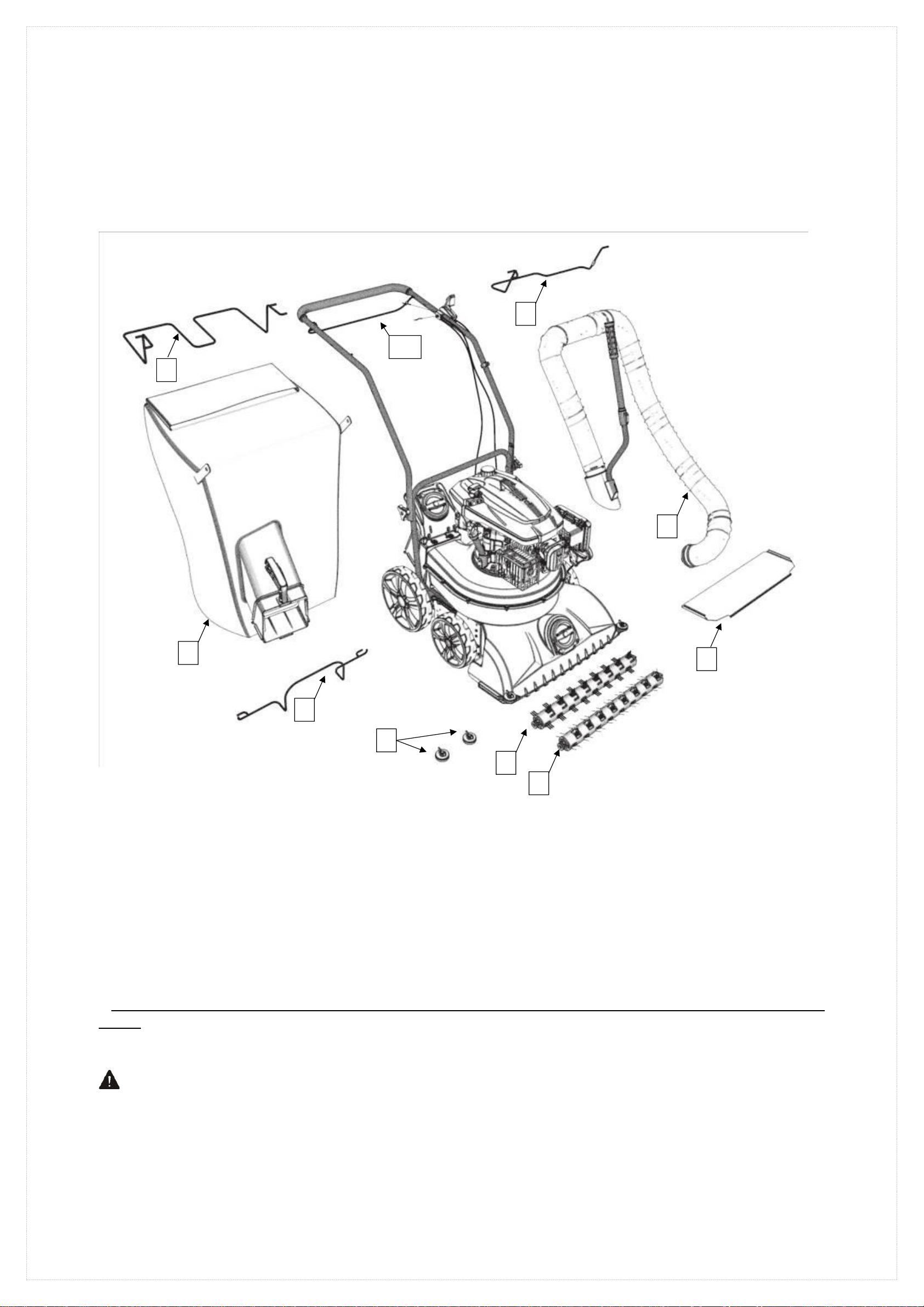
Included accessories
●Accessories and introduction
Accessories(1)Collection bag fixing bracket—Used to fixed collection bags (Must assembled)
Accessories(2)Collection bag—Collecting inhaled garbage (Must assembled)
△Accessories(3)Cleaning disk—Used to clean the ground (Optional)
△Accessories(4)Comb brush—Used to comb the lawn (Optional)
△Accessories(5)Auxiliary hose——Blowing or sucking away rubbish in areas that the machine cannot enter (Optional)
△Accessories(6)Suction port baffle—When the suction port is completely closed by the flap,Maximize the vacuum of the hose (Optional)
Accessories(7)Hose bracket—Used to suspend hoses and hang collection bags (Must assembled)
△Accessories(8)pulley—When an impact occurs, change the direction of the machine and protect the suction port (Optional)
△Accessories(9)Rear wheel drive lever—Used to drive rear wheel self-propelled (Optional)
△Accessories(10)Roller brush drive lever—Used to drive rear Roller brush (Optional)
●Note: When assembling the machine, please select one of the assemblies (3) and (4) according to your needs or work area, or
neither.
Warning: For your own safety, please read this manual before attempting to operate a new
device. Failure to follow instructions can result in serious personal injury. Take time to
familiarize yourself with the machine before each use.
2
1
7
3
4
5
6
8
9
10
02

Table of Contents
Included accessories...............................................................................................................................................................................2
Table of Contents....................................................................................................................................................................................3
Chapter 1 Safety and specification introduction.................................................................................................................................4
Chapter 2 Assembly instructions..........................................................................................................................................................8
Chapter 3 Product specification...........................................................................................................................................................13
Chapter 4 Instructions for use..............................................................................................................................................................14
Chapter 5 Lubrication instructions......................................................................................................................................................21
Chapter 6 Engine description...............................................................................................................................................................21
Chapter 7 Machine cleaning and storage............................................................................................................................................21
Chapter 8 Machine maintenance instructions....................................................................................................................................22
Chapter 9 Maintenance planning cycle...............................................................................................................................................23
Chapter 10 Troubleshooting and solutions.........................................................................................................................................24
Chapter 11 Environmental protection.................................................................................................................................................25
Chapter 12 Declaration of conformity.................................................................................................................................................26
Chapter 13 WARRANTY......................................................................................................................................................................27
Chapter 14 PRODUCT FAILURE.......................................................................................................................................................28
Chapter 15 WARRANTY EXCLUSIONS...........................................................................................................................................29
03

WARNING: If any of the labels are damaged or missing, replace them before operating the
equipment.
Chapter 1: Safety and specification introduction
Intended use
This blower is meant to be used for blowing leaves, dust or garden debris into a desired direction. It must not to be used for blowing
water, chemical products, flammable material, metal or wood and other dangerous objects.
This product is intended for private domestic use only. It must be used outdoors.
This product is not intended to be used in a closed room and places where exhausted gas and flames can be present.
The use of this product in case of rain or humid environments is prohibited.
Any other use might lead to damage of the appliance, property or personal injury.
1)Product safety warning
This appliance is not intended for use by persons (including children) with reduced physical, sensory or mental capabilities, or lack of
experience and knowledge, unless they have been given supervision or instruction concerning use of the appliance by a person
responsible for their safety.
Children should be supervised to ensure that they do not play with the appliance.
Never allow children, persons with reduced physical, sensory or mental capabilities or lack of experience and knowledge or people
unfamiliar with these instructions to use the machine, local regulations may restrict the age of the operator.
Never use the machine when people, especially children, or pets are nearby.
Remember that the operator or user is responsible for accidents or hazards occurring to persons or their belongings.
Do not disassemble the tool yourself. Disassembly, repair or verification must be made exclusively by qualified personnel.
WEAR CLOSE FITTING, TOUGH WORK CLOTHING that will provide protection, such as long slacks or trousers, safety work
shoes, heavy duty work gloves, hard hat, a safety face shield, or safety glasses for eye protection. The tool is extremely noisy and
requires the use of ear protection, such as a good grade of ear plugs or other sound barriers.
Always carry the machine by its handle; never use any other part of the machine.
REFUEL IN A SAFE PLACE. Open fuel cap slowly to release any pressure which may have formed in fuel tank. Always wipe unit
of fuel or oil spills before starting. To prevent a fire hazard, move at least 10 feet (3meters) from fueling area before starting.
TURN UNIT OFF before setting it down and also before installing or removing attachments.
KEEP ALL SCREWS AND FASTENERS TIGHT and the unit in good operating condition. Never operate this equipment if it is
improperly adjusted or not completely and securely assembled.
KEEP HANDLES DRY, clean and free of fuel mixture.
STORE EQUIPMENT AWAY FROM POSSIBLE IGNITION SOURCES, such as gas-powered water heaters, clothes dryers, or
oil-fired furnaces, portable heaters, etc.
ALWAYS KEEP the engine free of debris build-up.
OPERATION OF EQUIPMENT should always be restricted to mature and properly instructed individuals.
ALL PERSONS WITH RESPIRATORY PROBLEMS and persons operating blower in very dusty environments, should wear a dust
particle mask at all times. Paper dust masks are available at most paint and hardware stores.
Operate the machine only at reasonable hours - not early in the morning or late at night when people might be disturbed. Comply with
times listed in local ordinances.
Avoid using the machine in bad weather, especially when there is a risk of thunderstorms and lightning.
In case of accident, immediately stop using the machine. Turn the machine off and check the problem. Do not use the machine while
the machine is damaged.
If the machine should start making any unusual noise or vibration, immediately shut off the power source and allow the machine to
stop. Take the following steps before restarting and operating the machine:
a) Inspect for damage;
b) Replace or repair any damaged parts;
c) Check for and tighten any loose parts.
If the machine becomes clogged, shut-off the power source before cleaning debris.
Never operate the machine with defective guards or shields, or without safety devices in place.
Keep the power source clean of debris and other accumulations to prevent damage to the power source or possible fire.
Do not carry this machine while it is in operation. Always switch off the tool and always transport it by its handle and in order to
avoid accidents and a fuel leak.
Stop the machine and make sure that all moving parts have come to a complete stop
a) Whenever you leave the machine;
b) Before clearing blockages or unclogging chute;
04

c) Before checking, cleaning or working on the machine.
Do not tilt the machine while the power source is running.
Operate the machine at the lowest possible engine speed to do the job. Like this, vibration and noise levels as well as the tool’s wear
can be kept to a minimum.
Use rakes and brooms to loosen debris before blowing.
In dusty conditions, slightly dampen surfaces.
Use the full blower nozzle extension so the air stream can work close to the ground.
Watch out for children, pets, open windows etc. and blow debris safety away.
WARNING: DO NOT USE ANY OTHER FUEL than that recommended in your manual. Always follow instructions in the Fuel and
Lubrication section of this manual. Never use gasoline unless it is properly mixed with 2-cycle engine lubricant. Permanent damage to
engine will result, voiding manufacturer’s warranty.
DO NOT SMOKE while refueling or operating equipment.
DO NOT OPERATE UNIT WITHOUT A MUFFLER and properly installed muffler shield.
DO NOT TOUCH or let your hands or body come in contact with a hot muffler or spark plug wire.
DUE TO THE DANGER of exhaust fumes, never operate blower in a confined or poorly ventilated area.
NEVER POINT BLOWER in the direction of people, animals, buildings, automobiles, or open windows, etc.
DO NOT operate unit without inlet cover installed to prevent contact with impeller.
DO NOT set a hot engine down where flammable material is present.
DO NOT OPERATE UNIT FOR PROLONGED PERIODS. Rest periodically to prevent damage from vibration, damage to ears or
damage to the appliance.
Operate the machine in a recommended position and only on a firm, level surface.
Do not operate the machine on a paved or gravel surface where ejected material could cause injury.
WARNING: DO NOT ADD, REMOVE OR ALTER ANY COMPONENTS OF THIS PRODUCT. Doing so could cause personal injury
and/or damage the unit, voiding the manufacturer’s warranty.
DO NOT OPERATE UNIT WHILE TIRED, SICK OR UNDER THE INFLUENCE OF ALCOHOL OR DRUGS.
DO NOT operate your unit near or around flammable liquids or gases whether in or out of doors. An explosion and/or fire may result.
DO NOT WEAR loose clothing, scarfs, neck chains, unconfined long hair, and the like. Doing so could cause injury associated with
objects being drawn into the rotating parts.
DO NOT refuel a running engine or an engine that is hot.
Before using, always visually inspect to see that fasteners are secure, the housing is undamaged and that guards and screens are in
place. Replace worn or damaged components in sets to preserve balance. Replace damaged or unreadable labels.
Before starting the machine, make certain that the tube is empty.
Keep your face and body away from the nozzle.
Do not allow hands or any other part of the body or clothing inside the discharge chute or near any moving part.
Keep proper balance and footing at all times. Do not overreach. Never stand at a higher level than the base of the machine when
blowing material with it.
Always stand clear of the discharge zone when operating this machine.
To reduce the risk of hearing loss associated with sound level, hearing protection is required.
To reduce the risk of injury associated with contacting rotating parts, stop the engine before installing or removing attachments. Do
not operate without guard in place. Always disconnect the spark plug before performing maintenance or accessing any movable
parts.
Do not point the blower nozzle in the direction of people or pets.
Never run the unit without the proper equipment attached. When used as a blower, always install the blower tubes.
operate the machine only at reasonable hours – not early in the morning or late at night when people might be disturbed;
Do not to operate the machine near open windows.
use rakes and brooms to loosen debris before blowing
slightly dampen surfaces in dusty conditions or use mister attachment;
Limit the time of use of the tool. Take a time of rest between 2 operations. Do not work earlier or later in the night. Do be exposed to
noise and vibration for a prolonged time. Noise can bring damage to the ears.
This machine is extremely noisy. Always wear a hearing protection when use the tool.
In the event of accident or breakdown, stop to use the machine. Switch off the tool and wait until it completely stops. Check the
problem. In case of blockage, clear the blockage carefully. In case of breakdown, bring the tool to an after sales service for
inspection and reparation. Only use the tool when it is safely unblocked.
operate the machine only at reasonable hours – not early in the morning or late at night when people might be disturbed;
WARNING – there is danger from rotating parts; do not enter in contact with them.
05
Maintenance and storage
When the machine is stopped for servicing, inspection, or storage, or to change an accessory, shut off the power source and make sure
that all moving parts have come to a complete stop. Allow the machine to cool before making any inspections, adjustments, etc. Maintain
the machine with care and keep it clean.
Store the machine in a dry place out of the reach of children.
Always allow the machine to cool before storing.
Replace worn or damaged parts for safety. Use only genuine replacement parts and accessories.
Never attempt to override the interlocked feature of the guard.
Residuals risks
Even if you use this product in compliance with all safety requirements, potential risks of injury and damage remain. The following
hazards may arise from the structure and design of this product. Always be vigilant when using this product, so you can recognize and
manage the risks early. Rapid intervention can prevent serious injury and property damage. Turn off the tool if there are any malfunctions.
Have it checked by a qualified professional and have repairs carried out, if necessary, before using it again.
There are harmful health consequences resulting from the emission of vibrations if the product is used for long periods of time or not
properly managed and properly maintained.
There is risk of injury and property damage due to attachments or broken the sudden impact of hidden objects.
Risk of injury to persons and property caused by flying objects.
Prolonged use of this product exposes the operator to vibration and can produce so-called "white finger" disease. To reduce the risk,
wear gloves and keep your hands warm.
If any of the symptoms of "white finger syndrome" occur, seek immediate medical attention. Symptoms of the "white finger" include
numbness, loss of sensitivity, tingling, tingling, and pain, loss of strength, color changes or skin condition. These symptoms usually
appear on the fingers, hands or wrists. Risk increases at low temperatures.
Inhalation of particles of material blown.
Unattended projections.
Contact with foreign objects.
Contact with the tool in operation.
Hearing loss in the absence of correct hearing protection.
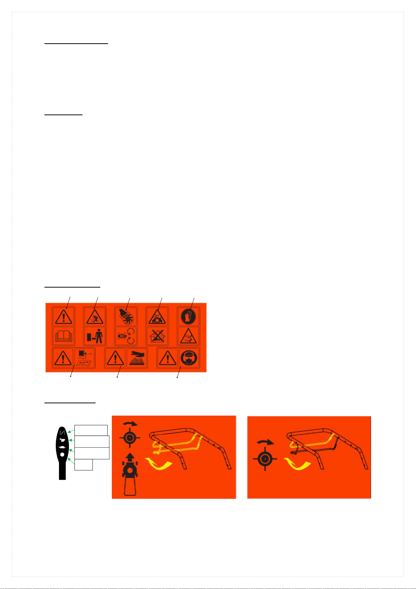
2)Indicator mark
A.1 A.2 A.3 A.4 A.5
A.1 Read the operating manual.
A.2 Keep the bystanders away, risk of projections.
A.3 Do not touch the rotating parts while operating.
A.4 Toxic gases; do not operate inside the house.
A.5 Please wear protective gloves; pay more attention to your hands
and feet to avoid injury.
A.6 When repairing, please pick up the spark plug and repair it
according to the operation manual.
A.7 Caution: The engine is hot.
A.8 Wear glasses and earplugs to protect the operator.
Fig.1 A.6 A.7 A.8
———————————————————————————————————————————————————————————————
3)Control mark
Fig.3
DY1P70FA
Throttle mark
Fig.4.1 △Self-propelled drive tag
Fig.4.2 △Roller brush drive mark
———————————————————————————————————————————————————————————————
Start
Low speed
stop
Fast speed
06

4)Parameter mark
Fig.5.1 Self-propelled parameter marker Fig.5.2 Hand push parameter marker
———————————————————————————————————————————————————————————————
5)LOGO mark
Fig.6
07

Chapter 2: Assembly instructions ……
●Your machine cannot be used immediately after it has been removed from the box. Please understand the name and function of each
part on the second page of this manual, and then assemble it with the installation steps described in the following figure. Note: The
shape of the part contained in the assembly diagram is not inconsistent with the actual part shape.
△Assembly step 1)Rear wheel drive lever assembly—Install the wheel drive lever as directed by the diagram below(Please
see Fig a-1, 2, 3)
Fig.a-1 Fig.a-2
Fig.a-3 Assembly completion diagram
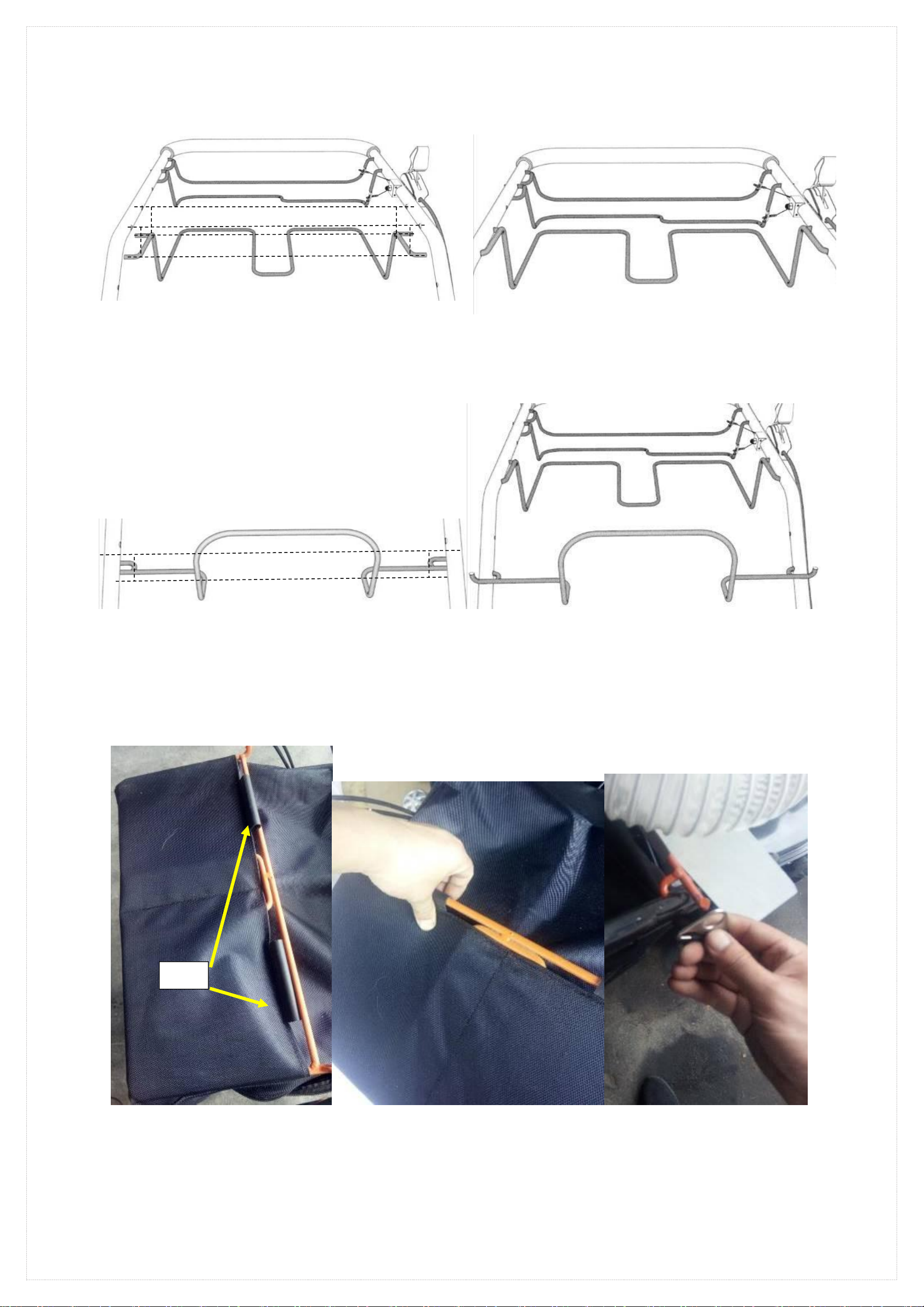
Assembly step 2 )Upper armrest assembly—Please put the upper handrail bar assembly on the lower handrail bar, guide
according to the dotted line, and then pass the two bolts through the mounting holes, and tighten the knob firmly.
Fig.7-1 Assembly guide
Fig.7-2 Assembly completion diagram
Part 1————Upper grab bar assembly
Part 2————Lower grab bar assembly
Part 3———— Knob M8
Part 4————Semi-circular head square neck bolt M8X46
Z-head penetrates into the fixing hole
Two ends of the tie rods, respectively inserted into the
left and right fixing holes of the handrail bar
The rope is at the lower end of the pole
1
4
2
3
08
Assembly 3)Collection bag fixing bracket assembly—Insert the left and right ends of the collection bag fixing bracket into the
corresponding four holes on the upper handrail bar assembly.
Fig.8-1 Assembly guide
Fig.8-2 Assembly completion diagram
Assembly step 4)Hose bracket assembly—Insert the left and right ends of the hose bracket into the corresponding two holes on the
upper grab bar assembly.
Fig.9-1 Assembly guide Fig.9-2 Assembly completion diagram
Assembly step 5)Collection bag assembly—Put the upper layer of the collection bag into the collection bag fixing bracket,The left and
right clips are fastened to the bracket. Hang the two left and right hanging plates on the ends of the hose fixing bracket. Press the baffle and
open the rear cover,Insert the collection bag interface into the back cover bracket.
Fig.10-1 Nested into the collection bag Fig.10-2 Fastening Card strip Fig.10-3 Assembly right hanging board
Buckle
09

Fig.10-4 Assembly left hanging board Fig.10-5 Press the baffle and open the rear cover Fig.10-6 Insert back cover bracket
Fig.10-7 Insert in place Fig.10-8 Installation completion diagram
hanging board
baffle
10

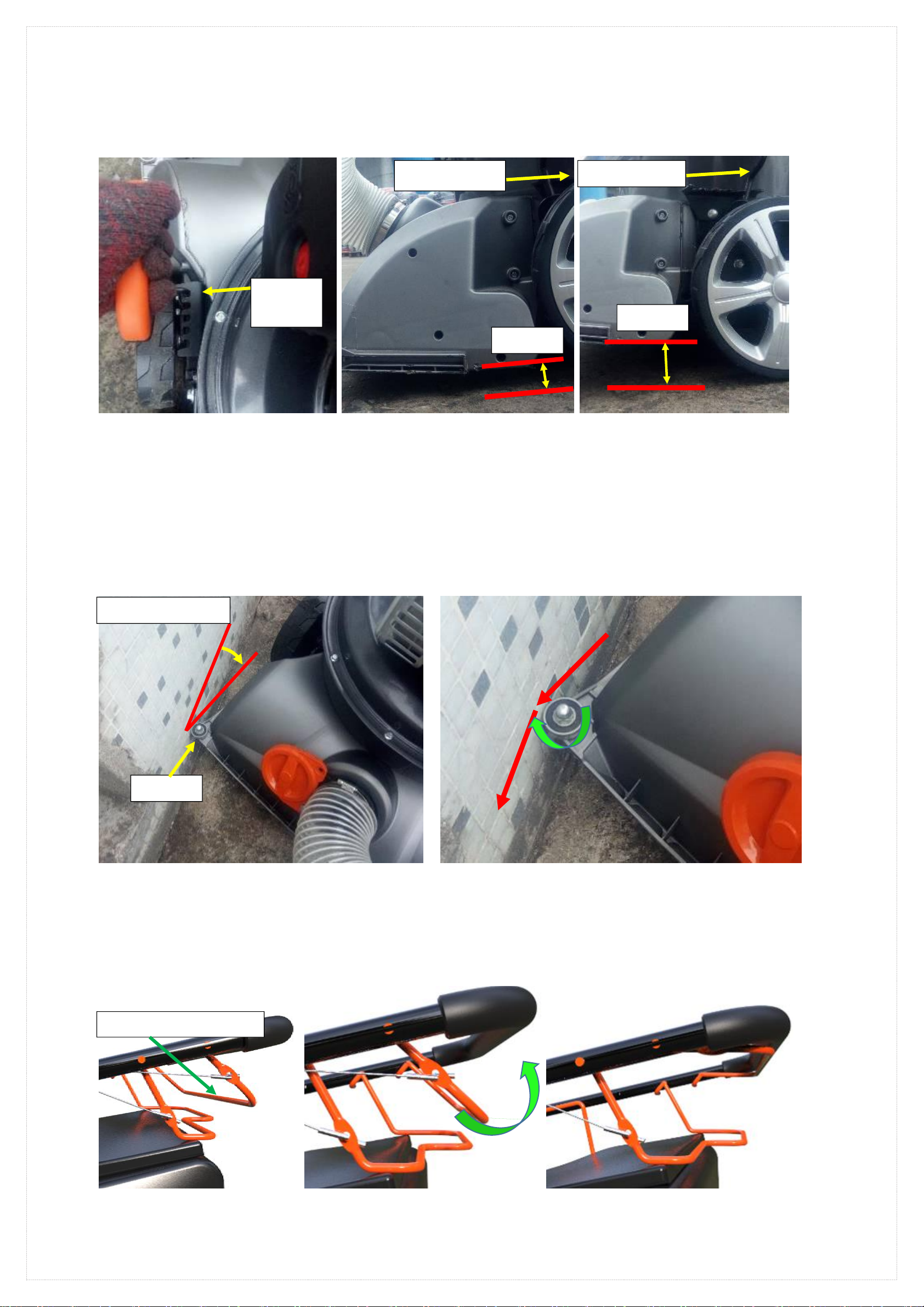
△Assembly step 6)Roller brush assembly—Lift the suction port, pull the quick release trigger and open the quick release cover.
Align the square end of the roller brush into the square shaft, insert the bearing end into the quick-release bracket bearing
mounting position, and pull the quick release trigger and fasten the upper cover.
Note: Before installing this component, it is necessary to turn off the machine engine to ensure that the entire machine is not working,
replace or install the roller brush.
Note: The quick release cover must be snapped into place. Pull the roller brush firmly without pulling the trigger, please check if the
roller brush will fall off; if it will fall, please reinstall this component.
Fig.11-1 Pull the trigger Fig.11-2 Open the top cover Fig.11-3 Insert square heart
Fig.11-4 Snap in bearing Fig.11-5 Fitting the cover Fig.11-6 Installation completion diagram
△Assembly step 7)Auxiliary hose assembly—Open the cover on the suction port, align the end of the hose into the interface fixing
bracket, and tighten it to the right according to the marking indication on the interface fixing bracket.
Fig.12-1 Open the cover Fig.12-2 Insert hose connector
quick release trigger
quick release cover
Square shaft
square heart
Bearing groove
Suction mouth
11

Fig.12-3 Screw the interface Fig.12-4 Complete the installation diagram
△Assembly step 8)Placement of the suction port baffle—Barbs the baffle on the hose fixing bracket。
●Note: This is where the baffle is placed when the hose is not being used for suction.
Fig.13-1 Hanging baffle Fig.13-2 Installation completion diagram
△Assembly step 9)pulley assembly—Assemble the pulley according to the instructions in the diagram and tighten the nut.
Fig.b-1
Fig.b-2 Right pulley installation completion diagram
Fig.b-3 Left pulley installation completion diagram
part 5- Butterfly nut
part 6- pulley
part 7- washer
part 8- fixed bolt
Hose tail port
5
6
7
8
12

Chapter 3: Product specification
●Host parameter ●Accessory parameters
Machine model
FAST175T-1
FAST175P-1
engine
DY1P70FA
DY1P70FA
Engine power
4 kW
4 kW
Engine emissions
173 cm³
173 cm³
Fuel capacity
1.5 L
1.5 L
Oil capacity
0.6 L
0.6 L
Engine speed
3400 /min
3400 /min
Walking speed
3.4 km/h
Collection bag capacity
150 L
150 L
Suction height
15mm-50mm
15mm-50mm
Suction air velocity
26 m/s
26 m/s
Air outlet speed
43 m/s
43 m/s
Guarantee the sound
pressure level
86 dB(A) K: 3dB(A)
86 dB(A) K: 3dB(A)
sound power level
105 dB(A)
105 dB(A)
Vibration value
6.7 m/s2K: 1,5m/s2
6.7 m/s2K: 1,5m/s2
Working slope angle
Less than 20 degrees
Less than 20 degrees
Startup mode
throttle
throttle
Machine size
Length 1305mm X width 602mm X
height 1080mm
Length 1305mm X width 602mm X
height 1080mm
net weight
46.6 Kg
42 Kg
Gross weight
50 Kg
46 Kg
Hose length
2500 mm
Pole telescopic
length
730 mm-990 mm
Hose diameter
90 mm
Hose vacuumn -
wind speed
40 m/s
Hose blowing -
wind speed
46 m/s
13

Chapter 4: Instructions for use
Warning: Before reading the instructions for use, make sure you understand the above and keep it in mind.
1)Start the machine
●Before starting, please check if the accessories you have assembled are completely fixed.
1. At the position of the marked organic oil label, turn on the oil dipstick and add the same amount of oil according to the oil capacity provided in the
parameter table of this manual (page 11).
2. In the position marked with the fuel label, unscrew the fuel tank cap and add the same amount of gasoline according to the fuel capacity provided
in the parameter table of this manual (page 11).
3. Make sure the microswitch rocker arm is closed. (See Fig 14-1, 2)
Fig.14-1 Switch rocker- Open state Fig.14-2 Switch rocker- Closed state
4. Please pull the throttle handle to the start state。(See Fig 15-1, 2)
Fig.15-1 Throttle handle- Engine stop Fig.15-2 Throttle handle- Engine start
6. Pull the engine start handle to start the engine. (See Fig 17)
●Note: Before you pull the handle, please pay attention to your surroundings,Clean up items that are sharp and can hurt your arms.
Fig.17 Start the machine
6. Adjust the engine to the maximum speed. (see Fig 18-1, 2)
Fig.18-1 Throttle handle- Engine startup state Fig.18-2 Throttle handle - Maximum speed status
Switch rocker
Switch rocker
Throttle handle
Press to the front end
Pull to the middle position
Leave gap size, size is
two index fingers
14
2)Adjust the height of the suction inlet
1. Pull the height adjustment handle out of the gear position slot and provide the height adjustment range according to the parameter table of this
manual (page 11) and select one gear position adjustment height from the 5 gear positions according to your use area or situation. (See Fig 19-1, 2,
3)
Fig.19-1 Pull out the handle Fig.19-2 Height distance Fig.19-3 Height distance
3) △The use and function of the guide wheel
1. During normal speed (3.4 km/h) travel,Impact at an angle of less than 45 degrees When striking road steps、height exceeds (50mm-80mm) and
fixed hard objects,The guide wheel will rub against the hard object, causing the direction of travel to change. Thereby avoiding the hard object and
preventing the machine from being damaged by the violent impact of the hard object. (See Fig 20-1, 2)
●Note: Do not exceed the normal self-propelled speed (please provide self-propelled speed according to the parameter table of this manual (page 11)) and
impact at an angle greater than 45 degrees. Such operation will cause the guide wheel to lose its function and cause the suction port to be damaged.
●Note: This function is an auxiliary function that protects the suction port for accidental impact. In normal times, please do not intentionally test its
strength. Please concentrate on operating the machine, slow down in advance and change direction to avoid hard objects.
Fig.20-1 Impact angle Fig.20-2 The role of the pulley
4) △Start and function of the roller brush
4)-1、Start roller brush
1. Please assemble the roller brush disc according to the procedure in 'Assembly Instructions', Assembly Step 5) roller brush Assembly (page 9).
2. After starting the machine, close the roller drive lever. (See Fig 21-1, 2, 3, 4))
Fig.21-1 Fig.21-2 Pull rod closing direction Fig.21-3 Clamping lever
Height up
handle
Lowest position
15mm
Highest position
50mm
pulley
Less than 45 degrees
Roller brush drive lever
15

Fig.21-4 Working diagram
4)-2、The role of Roller brush disk and the precautions for use
1. Roller brush disc is divided into Cleaning disk and Comb brush。(See Fig 22-1、2)
Fig.22-1 Sweepers Fig.22-2 Comb brush
2. The role of Sweeping disc. When you encounter rubbish stuck on the ground, wet leaves stuck on the ground and difficult to handle, please use the Sweeping
disc.Its brush does not damage the ground.
3. The role of Comb brush。On the lawn, please use the Comb brush;The steel claws attached to it will pick up the rubbish wrapped around the grass roots.
4. Precautions for the working area of the whole machine.
●Note: Do not use roller brushes or machines in harsh areas.(See fig 23-1、2)
Fig.23-1 Very lush lawn Fig.23-2 Very lush lawn
●Note:Do not use the machine to absorb soft fibers, fabrics。(See fig 24-1、2、3)
Fig.24-1 plastic rope Fig.24-2 Banded fibrous material Fig.24-3 Plastic bag
●Note: Do not work the machine in a garbage dump. (See Fig 25) ●Note: Do not try to absorb larger trash.(See Fig 26)
Fig.25 Garbage accumulation area Fig.26 Large trash
Roller brush rotation
direction
Swept into the trash direction
16
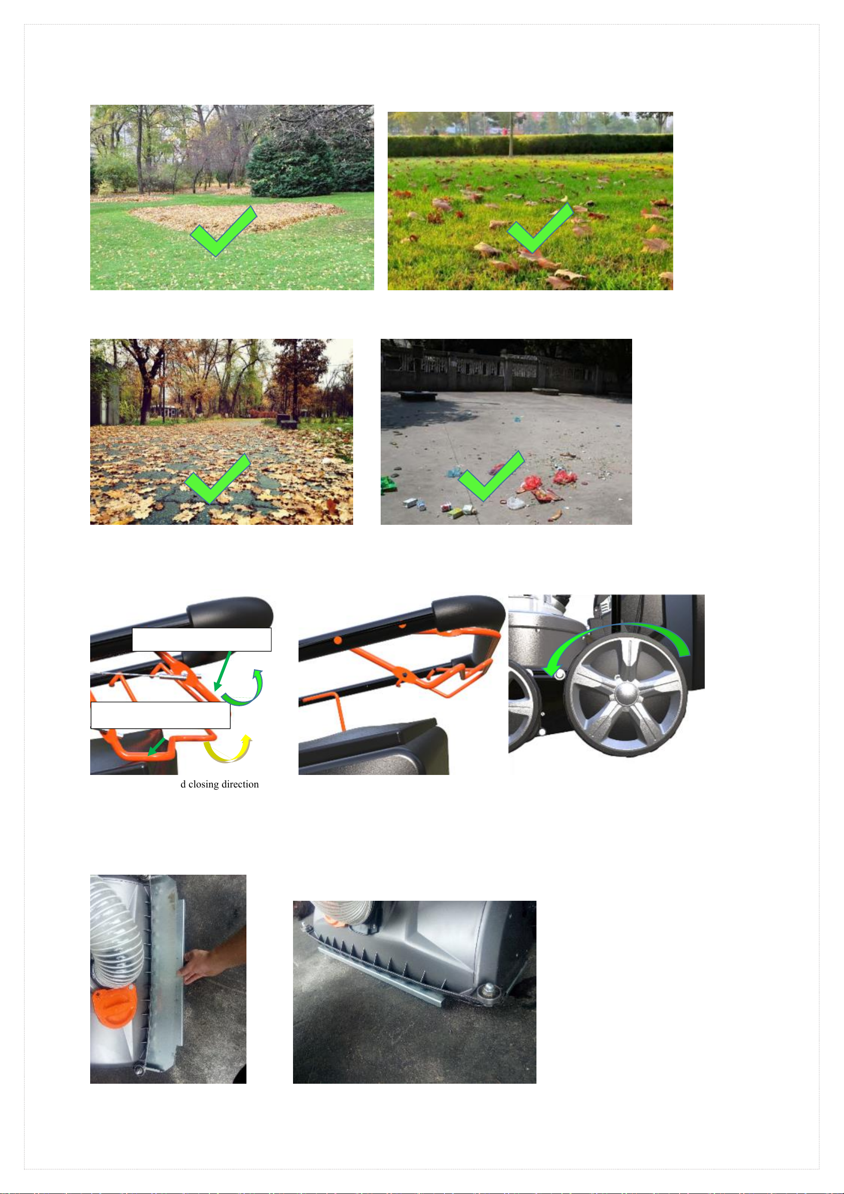
5. Reasonable work area
●Ground and lawn covered by fallen leaves. (See Fig 27-1, 2)
Fig.27-1 Fallen leaves on the lawn Fig.27-2 Fallen leaves on the lawn
●Ground and lawn with more leaves(Please see the picture 28-1, 2)
Fig.28-1 Fallen leaves on the road surface Fig.28-2 Scattered garbage on the road
5) △self-propelled operation instructions
1. After starting the machine, first close the roller brush drive lever and then close the self-propelled drive lever. (See Figure 29-1, 2, 3)
Fig.29-1 Pull rod closing direction Fig.29-2 Clamping lever Fig.29-3 Wheel rotation direction
6) △Auxiliary hose instructions for use
6)-1. Auxiliary hose function—Vacuum function
1. Please assemble the auxiliary hose according to the steps in the assembly instructions "Assembly Step 6" Auxiliary Hose Assembly" (page 9-10).
2. Insert the suction port baffle into the suction port。(see fig 30-1、2)
Fig.30-1 Insert baffle Fig.30-2 The baffle is inserted into place
roller brush drive lever
self-propelled drive lever
17
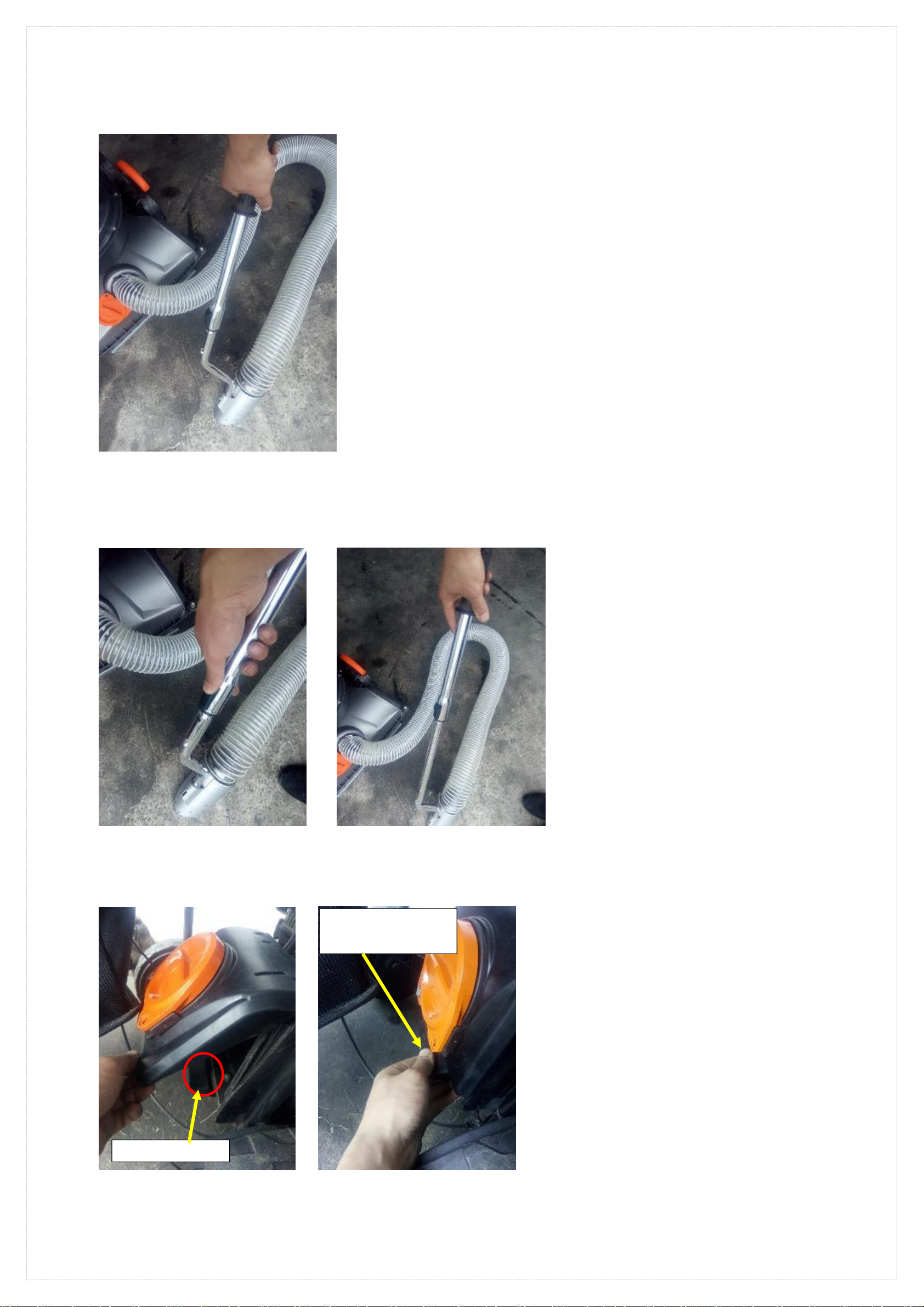
3. Start the machine,Point the hose mouth at the trash。(see fig 31)
●Note: When loading and unloading the hose, please turn off the engine first.
●Note: The suction port baffle is only used when the auxiliary hose is vacuumed.
Fig.31 Using a hose
6)-2. Auxiliary hose function—Telescopic function
1. Telescopic tube can adjust the height of different handle positions
2. Push the Lock with your thumb while adjusting the handle position forward or backward. (See Fig 32-1, 2)
Fig.32-1 Push open the lock Fig.32-2 Adjust the telescopic height
6)-2. Auxiliary hose function—Blow function
1. Close the rear cover(see fig 33-1、2、3)
Fig.33-1 Close the rear cover Fig.33-2 Close completely
Rear cover baffle
Rear cover baffle locks
the rear cover
18
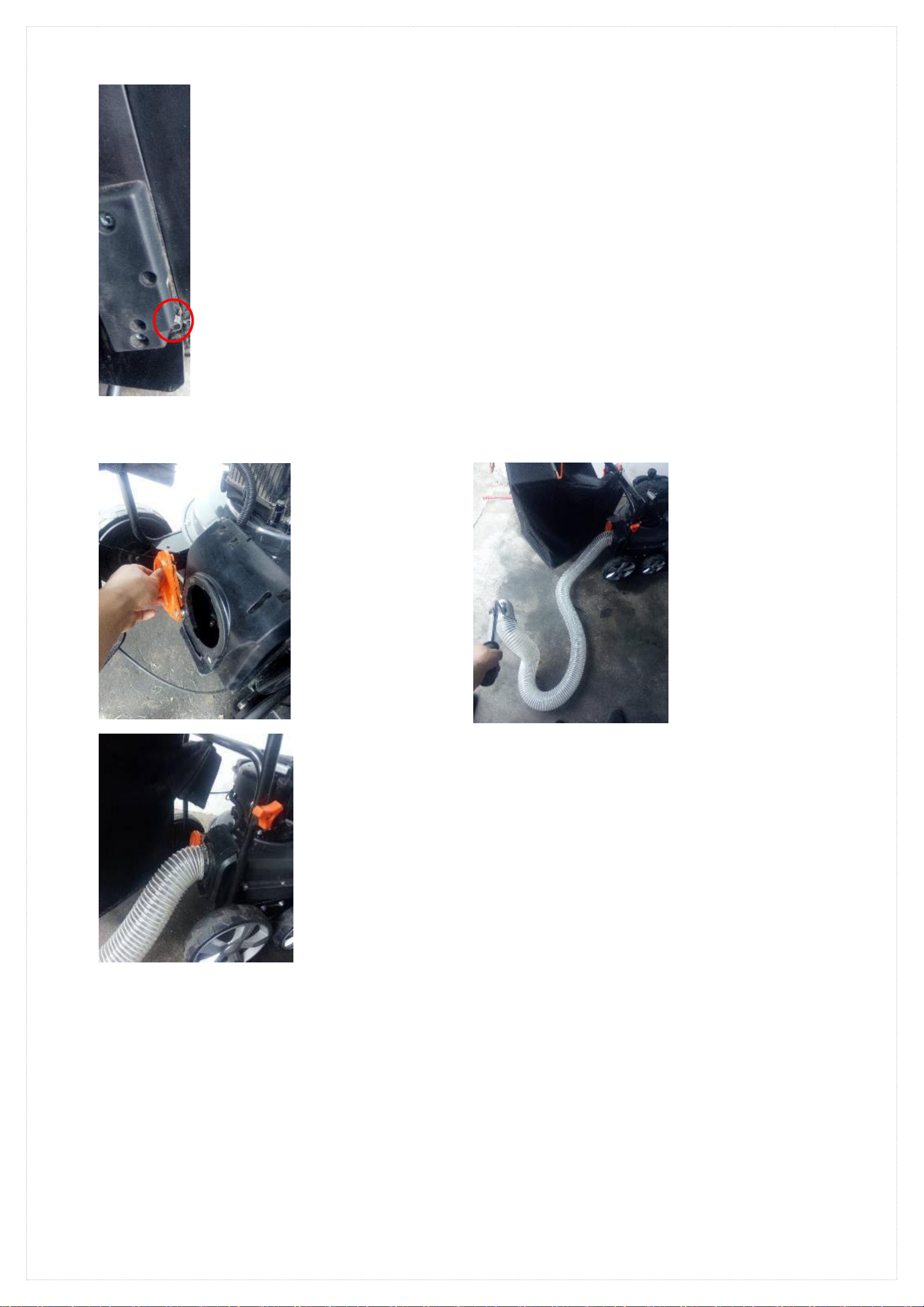
Fig.33-3 The switch rocker arm is fully closed
●Note: When using this function, please turn off the machine.
●Note: When fully closed, check that the rear panel bezel securely
locks the rear cover.
●Note: When fully closed, please check if the switch rocker arm has
been closed by the rear cover
●Note: It is strictly forbidden to remove the auxiliary hose when the
machine is working.
2. Attach the auxiliary hose tail connector to the rear cover hose
connector. (See Fig 34-1, 2)
Fig.34-1 Open the cover
Fig.34-2 Fixed interface
3. Start the machine,Point the hose mouth at the trash。(see fig 35)
Fig.35 Using a hose
6)-3. Auxiliary hose use precautions.
1. Please understand in detail the operation according to the "Precautions for the working area of the whole machine (pages 14-15)" and the following
precautions.
●Note: Please understand the parameters of the auxiliary hose in “Accessory Parameters (page 14)” before use.
●Note: When working, try to straighten the hose and work it to ensure maximum suction and wind speed.
●Note: It is strictly forbidden to point the hose to others or any non-working area during work.
●Note: It is strictly forbidden to load and unload the hose interface when the machine is started.。
●Note: Do not pull the hose to move the machine forward or backward.
●Note: Do not align the hose head with liquids, fire, and hazardous gases.
●Note: Do not pick up the trash that is larger than the hose port.
●Note: When the hose is clogged, stop the machine and then maintain it.
●Note: Keep the hose away from the engine silencer.
19
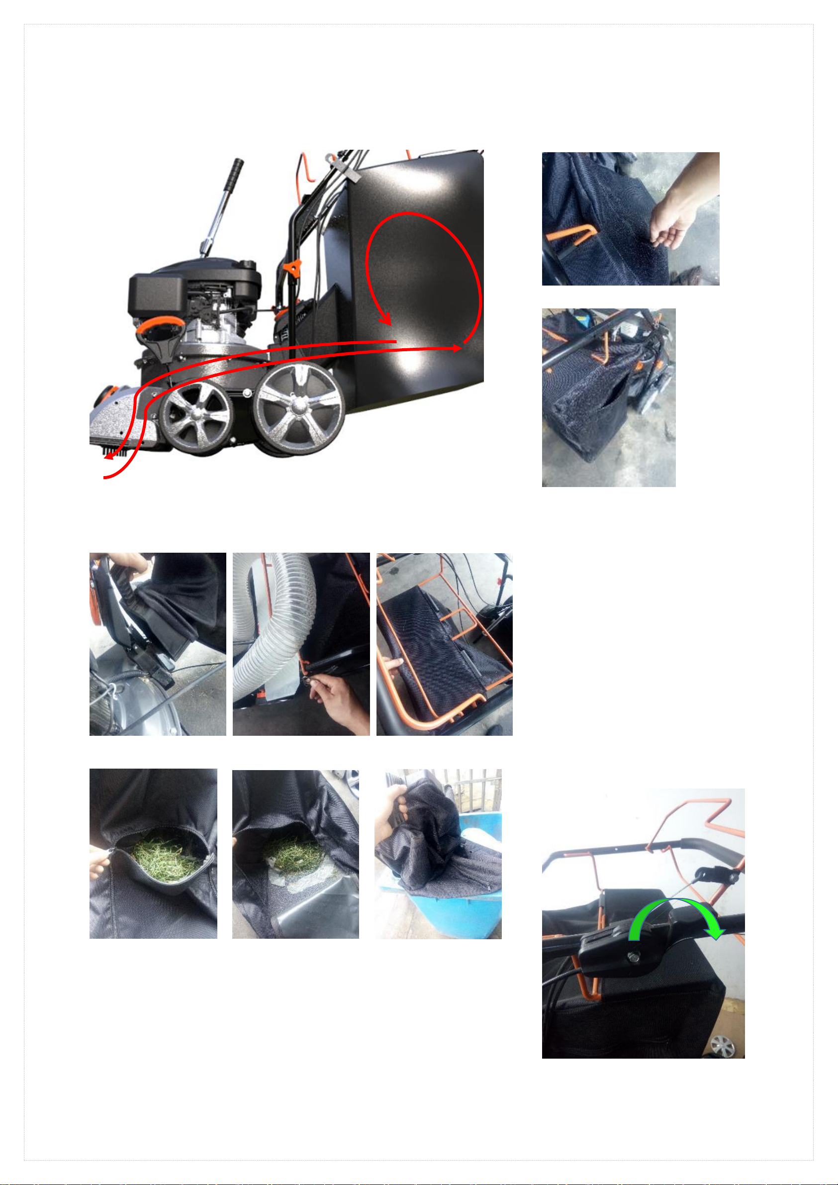
7)Instructions for using the collection bag
1. Please assemble the collection bag according to the steps in the assembly instructions "Assembly Step 4" Collection Bag Assembly" (page 7-8).
2. During the use of the machine, the dust inhaled by the machine may cause the venting holes of the collecting bag to become clogged or cause the
air to return when the collecting bag is full. At this time, please open the exhaust window zipper to make the collection bag ventilate; or check if the
collection bag is full. (See Fig 36-1, 2, 3)。
Fig.36-2 Open zipper
Fig.36-3
Fig.36-1 Reflux
3. When the collection bag is full, stop the machine; remove the collection bag and dump the
garbage.(see fig 37-1、2、3、4、5、6)
Fig.37-1 Fig.37-2 Fig.37-3
Take down the bag interface Remove the collection bag hanging plate Remove the collection bag
Fig.37-4 Fig.37-5 Fig.37-6
Open the collection bag mouth Open the collection bag mouth Pour out the garbage in the collection
bag
4. Collection bag precautions
●Note:1. When encountering backflow, please check if the venting hole of the collecting bag is
blocked;
2. Whether the collection bag is full;
3. Stop the machine and check if the collection bag interface is block。
●Note: When loading and unloading the collection bag, please make sure the machine has been
turned off.
●Note: Before starting the machine,
please check if the collection bag mouth is
closed.
●Note: It is strictly forbidden to open the
collection bag mouth when the machine is
working.
●Note: When cleaning the collection bag, do
not tap the collection bag with a tool.
8)Stop the engine.
Please understand the individual indications of
the throttle marks in the "Control Marks (page
5)".
1. Move the throttle handle to the flameout
position.(see fig 38)
Fig.38 Handle off position
20
This manual suits for next models
1
Table of contents
Other Feider Machines Blower manuals


Popular Blower manuals by other brands


Hydro-Force
Hydro-Force OmniPro OmniDry 2.9 Amp owner's manual

GreenWorks Pro
GreenWorks Pro 2404602 Operator's manual

NuTone
NuTone 335 instructions

Grizzly
Grizzly ELS 2614-2 E Translation of the original instructions for use

AL-KO
AL-KO LB 4060 Translation of the original instructions for use

HART
HART HGHBL02 Operator's manual