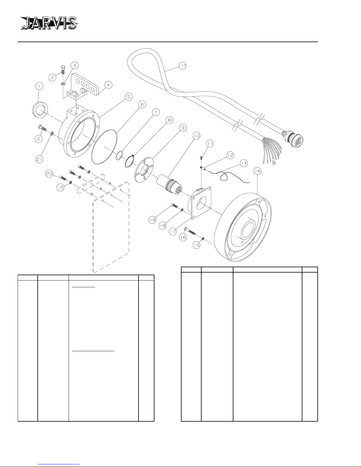
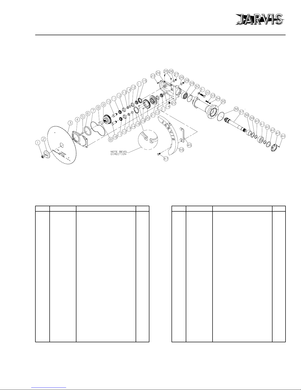
parts diagram and list
Model SEC 400 page 4 of 24
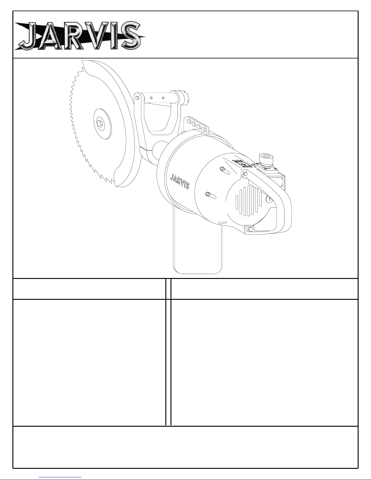
JARVIS PRODUCTS CORPORATION
33 ANDERSON ROAD, MIDDLETOWN, CONNECTICUT 06457--4926
TEL. 860--347--7271 FAX. 860--347--6978 WWW.jarvisproducts.com
6204004;.
®
1 1055749** Hex Head Screw 1
2 1012076 Blade Clamp 1
3 1023297 Standard Blade (16 inch) 1
1023284 Saw Blade (18 inch)
1023290 Saw Blade (21 inch)
4 1010360 Dowel Pin 2
5 1030053 Key 2
6 1020222 Blade Mounting Shaft 1
(includes item 4)
7 1055746 Socket Head Cap Screw 4
8 1038011 Grease Fitting 2
9 1002312 Gear Box Cover 1
10 1035371 O--ring 1
11 1035256 Shaft Seal 1
12 1032322 Bearing Plate 1
13 1021328 Ball Bearing 1
14 1026151 Crown Gear, Std 1
1026199 Crown Gear, Low Speed
15 1013212 Retaining Ring 1
16 1021276 Cylindrical Bearing 1
17 1016462 Gear Housing (2.84 dia.) 1
18 1055613 Hex Head Screw 2
19 1004245 Flat Washer 1
20 1042266* Ft Hdl Bkt (2.44 dia Gr Hsg) 1
1042339 Ft Hdl Bkt (2.84 dia Gr Hsg) 1
21 1055743 Set Screw 2
22 1018120 Trigger Lever (with Item 33) 1
23 1019140 Front Handle Grip 1
24 1010334 Threaded Pin 4
25 3005026 Switch Assembly 1
26 1063009 Wire Nut 2
27 1035375 O--ring 1
28 1002314 Front Handle Cover 1
29 1055744 Socket Head Cap Screw 3
30 1011305 Connector 1
31 1001122 Molded Plug and Wire 1
32 1059056* Hose Assembly 1
33 1014150 Compression Spring 1
ITEM PART NO. PART NAME QTY
34 1055753 Hex Head Screw 7
35 1004232 Split Lock Washer 7
36 1035372 O--ring 1
37 1021327 Needle Bearing 1
38 1026164 Pinion Gr. Sft (Splined, 15T) 1
1026180* Pinion Gr. Sft (Tang, 15T)
1026198 Pinion Gr. Sft (Splined, 13T)
Low Speed
39 1063220 Connector 1
40 1036190 Inner Ring Bushing 1
41 1013237 Retaining Ring 1
42 1013243 Retaining Ring 2
43 1021329 Ball Bearing 1
44 1035537 Oil Seal 1
45 1013208 Thrust Ring 1
46 1055617 Socket Head Cap Screw 6
47 1011301 Splined Coupling 1
48 1035534 O--ring 1
49 1030052* Key 2
50 1054132* Special Screw 1
51 1035367 Guard Gasket 1
52 1055748 Socket Head Cap Screw 2
53 1038025* Grease Relief Fitting 1
54 1050607 Hex Head Plug 1
55 1024125 Blade Guard (16 inch blade) 1
1024128 Blade Guard (18 inch blade)
1024131 Blade Guard (21 inch blade)
56 1055750 Hex Head Screw 2
3016271 Gear Hsg. Assy (incls. 1, 2,
4--17, 34--38, 40--46 and 54)
3016381 Gear Hsg. Assy, Low Speed
3019143 Front Handle Assy (incls.
items 18--31, 33, 39 and 52)
3011022 Coupling and Seal Assy
(incls. items 47 and 48)
3013005 Thrust Ring Seal Assy
(incls. items 44 and 45)
ITEM PART NO. PART NAME QTY
Figure A
*
*
*
*
*
**
***
* For spare parts only, not in current tools.
** Tighten to 65 lbf--ft.
*** Install open end facing blade.