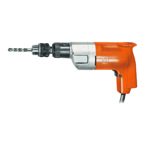
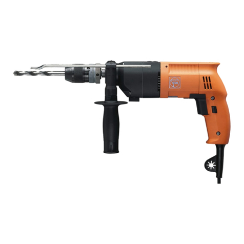
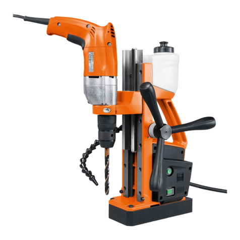
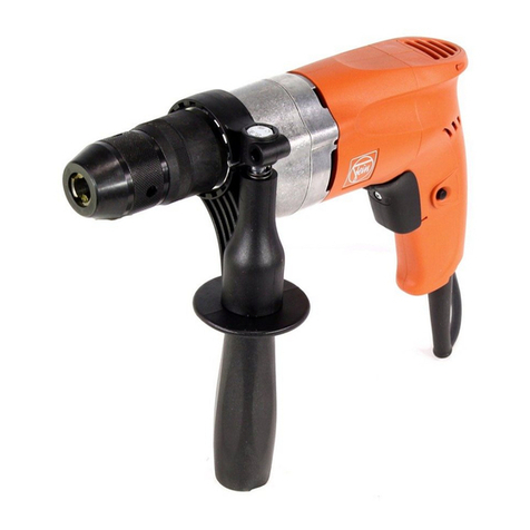
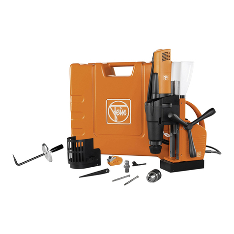
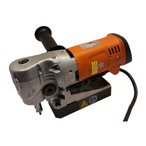
DSc 648
To
be handed to
the
workshop!
Operating instructions
for·
the
double insulated and radio suppressed
Two
Speed Percussion Drill type DSc
648
and type DSc 7
48
(42
Volts)
1.
Technical
Data
Type
of
current
:
""
Double
insulation
without
earth
wire
according
to
VDE 0740
Radio
suppressed
according
to
VDE 0875
Capacity
in
Net
weight
Type
stone
steel
Speed
R.P.M.
Percussions
Input
Output
with
chuck
I I
full
load
full
load
Watts
Watts
in.
mm
in.
mm
DSc 648 }
1st
sp
e
ed
5/s 16
DSc
748 13
/16
30
(42V)
2nd
speed
3/s
10
2.
Operation
Main
voltage
must
correspond
to
the
operation
voltage
marked
on
the
rating
plate.
Switch
in
"Off"
position.
1
~,
To
prevent overbridging of
the
protecting insulation,
no
additio-
nal
marking
plates
and
signs
must
be
riveted
or
screwed.
We
recommend
the
use
of
transfers.
Changing
of
the
speed
Push
slide
(61)
into
the
position
I
or
II.
Change
speed
only
at
stand-still
of
the
machine.
Percussion
mechanism:
The
rotatable
sleeve
(69)
engages
and
disengages
the
percussion
mechanism
steplessly.
The
final
po-
sition
is
marked.
3.
Maintenance
and
Lubrication
Pull
out
plug
before
carrying
out
any
maintenance
work.
Twice
a
week
gr~ase
percuss
i
on
mechanism
with
a
grease
gun.
After
300
working
hours
.
clean
air
openings
of
the
motor
hous-
ing.
Blow
out
motor
with
dry
pneumatic
air.
Renew
the
gear
grease.
Loosen
screws
(80, 81)
and
take
off
percussion
drill
head.
Only
use
the
Fein
special
grease
Sst
i.
After
900
working
hours
clean
machine
thoroughly.
Rinse
gears
in
clean
solvent
and
pack
with
fresh
grease
Sst
1.
Rinse
ball
bearings
in
clean
solvent
and
pack
with
fresh
grease
for
ball
bearings
Sst
1.
Dismantling
see
paragraph
4.
BE
234/e X 9.
71
lbs
kg
370
6000
500 300 9.1
4.1
900 14500
Quantity
Order
Contents
Type
of
grease
Ref
e
rence
oz
g
oz
g
Sst 1 13/ 4
50
MZ
60-3/Sst l 31
/s
90
Clean
electric
parts
'
only
dry.
Replace
.
carbon
brushes
when
they
have
worn
down
to
7 mm
(0.28 in).
To
replace
brushes
see
paragraph
4,
pos
iti
ons
1
and
3.
Only
use
Fein
carbon
brushes.
After
fitting
new
br
ush
es check
that
the
y
mo
ve
easily
in
th
e
ir
holder.
Run
tool
unloaded
for
about
15
min
.
Check
connection
cable
at
regular
intervals.
To
replace
unscrew
screws
(20,
21),
remove
cover
(19),
loosen
screws
(16)
of
the
ter-
minal
clamp
and
clamp
off
cable
from
switch
(12).
No
claims
can
be
entertained
f
or
damage
due
to
negligent
main-
te
nance
and
inadequ
a
te
lubricat
ion.
