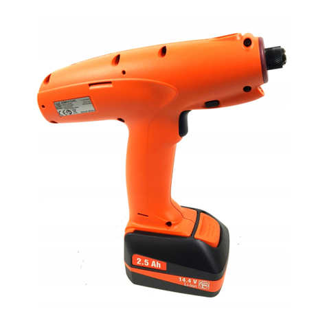
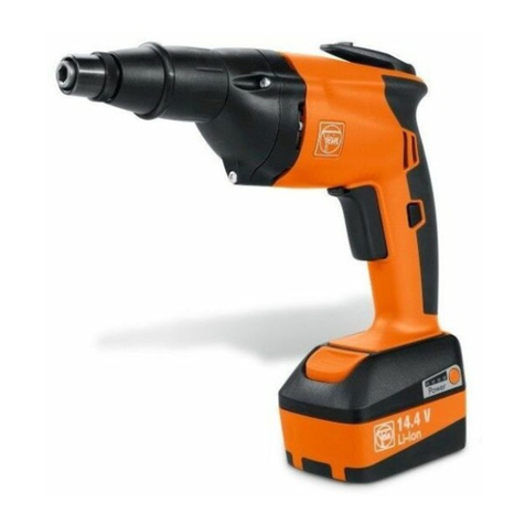
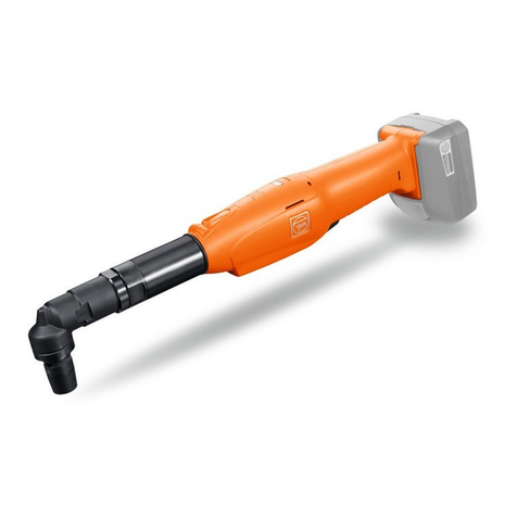
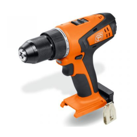
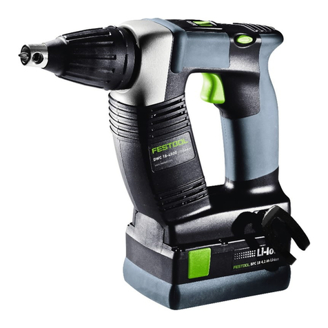
Fein Handy Master ABS9 User manual

© C. & E. FEIN GmbH. Printed in PRC. Abbildungen unverbindlich. Technische Änderungen vorbehalten. 3 41 01 031 06 1 BY 2011.05 DE.
EN 60745, EN 55014
2006/42/EG, 2004/108/EG
Hammersdorf
Quality Manager Dr. Schreiber
Manager of R&D department
FEIN Service
C. & E. FEIN GmbH
Hans-Fein-Straße 81
D-73529 Schwäbisch Gmünd-Bargau
www.fein.com
ABS9 7 113 01
ABS12 7 113 02
ABS14 7 113 03
ABS18 7 113 06
ASB14 7 104 03
ASB18 7 104 04
ASB_ABS 9-18 - Titel-Rück.fm Seite 1 Freitag, 20. Mai 2011 9:47 09

2
de 5es 35 sv 65 pl 95
en 11 pt 41 fi 70 ru 102
fr 17 el 47 hu 76
it 23 da 53 cs 82
nl 29 no 59 sk 88
3 41 01 031 06 1.book Seite 2 Dienstag, 10. Mai 2011 9:32 09

3
7
6
5
3
4
2
8
click
1ABS12
ABS14
ABS18
ASB14
ASB18
ABS18
ASB18
3 41 01 031 06 1.book Seite 3 Dienstag, 10. Mai 2011 9:32 09

4
d
b
c
e
9a
3 41 01 031 06 1.book Seite 4 Dienstag, 10. Mai 2011 9:32 09

5
de
Original Betriebsanleitung H
ANDY
M
ASTER
Akku-Bohrschrau-
ber und Akku-Schlagbohrschrauber.
Verwendete Symbole, Abkürzungen und
Begriffe.
Die in dieser Betriebsanleitung und ggf. auf dem Elektro-
werkzeug verwendeten Symbole dienen dazu, Ihre Auf-
merksamkeit auf mögliche Gefährdungen bei der Arbeit
mit diesem Elektrowerkzeug zu lenken.
Sie müssen die Bedeutung der Symbole/Hinweise verste-
hen und sinngemäß handeln, um das Elektrowerkzeug
effizienter und sicherer zu gebrauchen.
Die Sicherheitswarnungen, Hinweise und Symbole sind
kein Ersatz für vorschriftsgemäße Maßnahmen zur
Unfallprävention.
Symbol Erklärung
➤
Handlung des Bedieners
Allgemeines Verbotszeichen. Diese Handlung ist verboten!
Rotierende Teile des Elektrowerkzeugs nicht berühren.
Den Anweisungen im nebenstehenden Text oder Grafik folgen!
Die beiliegenden Dokumente wie Betriebsanleitung und Allgemeine Sicherheitshinweise
unbedingt lesen.
Schlagen Sie zum besseren Verständnis die Klappseite am Beginn dieser Betriebsanleitung auf.
Vor diesem Arbeitsschritt den Akku aus dem Elektrowerkzeug entfernen. Sonst besteht Ver-
letzungsgefahr durch unbeabsichtigtes Anlaufen des Elektrowerkzeugs.
Beim Arbeiten Augenschutz benutzen.
Beim Arbeiten Gehörschutz benutzen.
Die Hinweise im nebenstehenden Text beachten!
Bestätigt die Konformität des Elektrowerkzeugs mit den Richtlinien der Europäischen
Gemeinschaft.
Dieser Hinweis zeigt eine möglicherweise gefährliche Situation an, die zu ernsten Verletzun-
gen oder zum Tod führen kann.
Ausgemusterte Elektrowerkzeuge und andere elektrotechnische und elektrische Erzeugnisse
getrennt sammeln und einer umweltgerechten Wiederverwertung zuführen.
Erzeugnis mit doppelter oder verstärkter Isolierung
NiCd Nickel-Cadmium Akku
NiMH Nickel-Metall-Hydrid Akku
WARNUNG
3 41 01 031 06 1.book Seite 5 Dienstag, 10. Mai 2011 4:52 16

6
de
Zu Ihrer Sicherheit.
Lesen Sie alle Sicherheitshinweise und
Anweisungen.
Versäumnisse bei der
Einhaltung der Sicherheitshinweise
und Anweisungen können elektrischen Schlag, Brand
und/oder schwere Verletzungen verursachen.
Bewahren Sie alle Sicherheitshinweise und Anweisungen
für die Zukunft auf.
Verwenden Sie dieses Elektrowerkzeug nicht,
bevor Sie diese Betriebsanleitung und die
Betriebsanleitung des zu verwendenden Akku-
Ladegeräts sowie die beiliegenden „Allgemeinen Sicher-
heitshinweise“ (Schriftennummer 3 41 30 054 06 1)
gründlich gelesen und vollständig verstanden haben.
Bewahren Sie die genannten Unterlagen zum späteren
Gebrauch auf und überreichen Sie diese bei einer Wei-
tergabe oder Veräußerung des Elektrowerkzeugs.
Beachten Sie ebenso die einschlägigen nationalen
Arbeitsschutzbestimmungen.
Bestimmung des Elektrowerkzeugs:
ABS9/ABS12/ABS14/ABS18
handgeführter Bohrschrauber zum Ein- und Ausdrehen
von Schrauben und Muttern und zum Bohren und
Schrauben in Metall, Holz, Kunststoff und Keramik sowie
zum Gewindeschneiden mit den von FEIN zugelassenen
Einsatzwerkzeugen und Zubehör ohne Wasserzufuhr in
wettergeschützter Umgebung.
ASB14/ASB18
handgeführter Schlagbohrschrauber zum Ein- und Aus-
drehen von Schrauben und Muttern und zum Bohren
und Schrauben in Metall, Holz, Kunststoff und Keramik
sowie zum Gewindeschneiden und Schlagbohren in
Beton, Gestein und Ziegel mit den von FEIN zugelasse-
nen Einsatzwerkzeugen und Zubehör ohne Wasserzu-
fuhr in wettergeschützter Umgebung.
Spezielle Sicherheitshinweise.
Tragen Sie Gehörschutz beim Schlagbohren.
Die Einwir-
kung von Lärm kann Gehörverlust bewirken.
Benutzen Sie mit dem Gerät gelieferte Zusatzhandgriffe.
Der Verlust der Kontrolle kann zu Verletzungen führen.
Halten Sie das Elektrowerkzeug an den isolierten Griffflä-
chen, wenn Sie Arbeiten ausführen, bei denen das Einsatz-
werkzeug oder die Schraube verborgene Stromleitungen
treffen kann.
Der Kontakt mit einer spannungsführenden
Leitung kann auch metallene Teile des Elektrowerkzeu-
ges unter Spannung setzen und zu einem elektrischen
Schlag führen.
Achten Sie auf verdeckt liegende elektrische Leitungen,
Gas- und Wasserrohre.
Kontrollieren Sie vor Arbeitsbe-
ginn den Arbeitsbereich z. B. mit einem Metallortungsge-
rät.
ASB18/ABS18: Halten Sie das Elektrowerkzeug fest mit bei-
den Händen und sorgen Sie für einen sicheren Stand.
Das
Elektrowerkzeug wird mit zwei Händen sicherer geführt.
Sichern Sie das Werkstück.
Ein mit einer Spannvorrich-
tung gehaltenes Werkstück ist sicherer gehalten als in
Ihrer Hand.
Bearbeiten Sie kein asbesthaltiges Material.
Asbest gilt als
krebserregend.
Halten Sie das Elektrowerkzeug gut fest und setzen es nur
ausgeschaltet auf Schrauben oder Muttern.
Es können
kurzzeitig hohe Reaktionsmomente auftreten.
Es ist verboten Schilder und Zeichen auf das Elektrowerk-
zeug zu schrauben oder zu nieten.
Eine beschädigte Isolie-
rung bietet keinen Schutz gegen elektrischen Schlag.
Verwenden Sie Klebeschilder.
Verwenden Sie kein Zubehör, das vom Hersteller nicht spe-
ziell für dieses Elektrowerkzeug vorgesehen und empfohlen
wurde.
Nur weil Sie das Zubehör an Ihrem Elektrowerk-
zeug befestigen können, garantiert das keine sichere Ver-
wendung.
Reinigen Sie regelmäßig die Lüftungsöffnungen des Elektro-
werkzeugs mit nichtmetallischen Werkzeugen.
Das Motor-
gebläse zieht Staub in das Gehäuse. Dies kann bei
übermäßiger Ansammlung von Metallstaub elektrische
Gefährdungen verursachen.
Zeichen Einheit international Einheit national Erklärung
V V elektrische Gleichspannung
n /min /min Leerlaufdrehzahl/Schlagzahl
M… Nm Nm Drehmoment
Ø
mm mm Durchmesser eines runden Teils
L
wA
dB dB Schallleistungspegel
L
pA
dB dB Schalldruckpegel
L
pCpeak
dB dB Spitzenschalldruckpegel
K… Unsicherheit
m/s
2
m/s
2
Schwingungsemissionswert nach EN 60745
(Vektorsumme dreier Richtungen)
m/s
2
m/s
2
mittlerer Schwingungswert für Bohren in Metall
m/s
2
m/s
2
mittlerer Schwingungswert für Schlagbohren in
Beton
m, s, kg, A, mm, V,
W, Hz, N, °C, dB,
min, m/s
2
m, s, kg, A, mm, V,
W, Hz, N, °C, dB,
min, m/s
2
Basis- und abgeleitete Einheiten aus dem Interna-
tionalen Einheitensystem
SI
.
h
,
D
h
,
ID
WARNUNG
3 41 01 031 06 1.book Seite 6 Dienstag, 10. Mai 2011 4:52 16

7
de
Bringen Sie den Drehrichtungsumschalter des Elektrowerk-
zeugs vor allen Arbeiten am Elektrowerkzeug sowie bei des-
sen Transport und Aufbewahrung in Mittelstellung.
Läuft
das Elektrowerkzeug unbeabsichtigt an, besteht Verlet-
zungsgefahr.
Verwendung und Behandlung des Akkus
(Akkublocks)
Um Gefährdungen wie Verbrennungen, Brand, Explosion,
Hautverletzungen und andere Verletzungen beim Umgang mit
den Akkus zu vermeiden, beachten Sie folgende Hinweise:
Akkus dürfen nicht zerlegt, geöffnet oder zerkleinert wer-
den. Setzen Sie die Akkus keinen mechanischen Stößen aus.
Bei Beschädigung und unsachgemäßem Gebrauch des
Akkus können schädliche Dämpfe und Flüssigkeiten aus-
treten. Die Dämpfe können die Atemwege reizen. Aus-
tretende Akkuflüssigkeit kann zu Hautreizungen oder
Verbrennungen führen.
Falls aus dem beschädigten Akku ausgetretene Flüssigkeit
angrenzende Gegenstande benetzt hat, überprüfen Sie die
betroffenen Teile, reinigen Sie diese oder tauschen Sie sie
gegebenenfalls aus.
Setzen Sie den Akku nicht der Hitze oder dem Feuer aus.
Lagern Sie den Akku nicht im direkten Sonnenlicht.
Entnehmen Sie den Akku erst dann aus seiner Originalver-
packung, wenn er verwendet werden soll.
Nehmen Sie den Akku vor Arbeiten am Elektrowerkzeug aus
dem Elektrowerkzeug.
Läuft das Elektrowerkzeug unbeab-
sichtigt an, besteht Verletzungsgefahr.
Nehmen Sie den Akku nur bei ausgeschaltetem Elektro-
werkzeug ab.
Halten Sie Akkus von Kindern fern.
Halten Sie den Akku sauber und geschützt vor Feuchtigkeit
und Wasser.
Reinigen Sie die verschmutzten Anschlüsse
des Akkus und des Elektrowerkzeugs mit einem trocke-
nen, sauberen Tuch.
Verwenden Sie nur intakte original FEIN-Akkus, die für Ihr
Elektrowerkzeug bestimmt sind.
Beim Arbeiten mit und
Laden von falschen, beschädigten, reparierten oder auf-
gearbeiteten Akkus, Nachahmungen und Fremdfabrika-
ten besteht Brandgefahr und/oder Explosionsgefahr.
Befolgen Sie die Sicherheitshinweise in der Betriebsanlei-
tung des Akku-Ladegeräts.
Hand-Arm-Vibrationen
Der in diesen Anweisungen angegebene Schwingungspe-
gel ist entsprechend einem in EN 60745 genormten
Messverfahren gemessen worden und kann für den Ver-
gleich von Elektrowerkzeugen miteinander verwendet
werden. Er eignet sich auch für eine vorläufige Einschät-
zung der Schwingungsbelastung.
Der angegebene Schwingungspegel repräsentiert die
hauptsächlichen Anwendungen des Elektrowerkzeugs.
Wenn allerdings das Elektrowerkzeug für andere
Anwendungen, mit abweichenden Einsatzwerkzeugen
oder ungenügender Wartung eingesetzt wird, kann
der Schwingungspegel abweichen. Dies kann die Schwin-
gungsbelastung über den gesamten Arbeitszeit-
raum deutlich erhöhen.
Für eine genaue Abschätzung der Schwingungsbelas-
tung sollten auch die Zeiten berücksichtigt werden, in
denen das Gerät abgeschaltet ist oder zwar läuft, aber
nicht tatsächlich im Einsatz ist. Dies kann die Schwin-
gungsbelastung über den gesamten Arbeitszeitraum
deutlich reduzieren.
Legen Sie zusätzliche Sicherheitsmaßnahmen zum
Schutz des Bedieners vor der Wirkung von Schwingun-
gen fest wie zum Beispiel: Wartung von Elektrowerk-
zeug und Einsatzwerkzeugen, Warmhalten der Hände,
Organisation der Arbeitsabläufe.
Auf einen Blick.
Die nachfolgend verwendete Nummerierung
der Bedienelemente bezieht sich auf die Abbil-
dungen am Anfang dieser Betriebsanleitung.
1 Schnellspann-Bohrfutter
Werkzeug aufnehmen und spannen.
2 Drehmoment-Einstellring mit Bohrstufe/Schlagbohr-
stufe (ASB14, ASB18)
Einstellen des Drehmomentes.
Betriebsart „Bohren“ oder „Schlagbohren“ auswählen.
3 Umschalter der Getriebestufe für langsame oder
schnelle Drehzahl
(ABS12, ABS14, ABS18, ASB14, ASB18)
Drehzahl einstellen.
4 Zusatzhandgriff mit Tiefenanschlag (ABS18, ASB18)
Elektrowerkzeug mit zweiter Hand halten.
Zur Einstellung der Bohr- bzw. Schraubtiefe mit Tie-
fenanschlag arbeiten.
5 Drehrichtungsumschalter Rechtslauf oder Linkslauf
Drehrichtung wählen.
6 Schalter
Elektrowerkzeug ein- und ausschalten.
7 Akku
Akku von Elektrowerkzeug abnehmen und mit
Ladegerät laden.
8 Entriegelungstaste
Taste betätigen und Akku vom Elektrowerkzeug
abziehen.
9 Mitgeliefertes Zubehör
Werkzeugkoffer (9a),
2 Akkus (9b),
Akku-Ladegerät (9c),
Bit (Kreuzschlitz Pozi Gr. 2 und 3) (9d),
Bit (Philips Gr. 2 und Schlitz Gr. 6) (9e).
Betriebsanweisungen.
Akku laden.
Lesen Sie vor dem ersten Ladevorgang die
Betriebsanleitung des Ladegeräts.
Laden Sie vor der ersten Inbetriebnahme den Akku
vollständig auf.
➤
Entriegeln Sie den Akku (7) durch Drücken der
Entriegelungstaste (8) und ziehen Sie den Akku
nach vorn aus dem Griff. Wenden Sie keine
Gewalt an.
➤
Schließen Sie das Ladegerät an die Steckdose an,
schieben Sie den Akku auf das Ladegerät und laden
Sie den Akku. Stecken Sie nach Ende des Ladevor-
ganges den Akku am Elektrowerkzeug auf und zie-
hen Sie den Stecker des Ladegerätes aus der
Steckdose.
3 41 01 031 06 1.book Seite 7 Dienstag, 10. Mai 2011 4:52 16
8
de
Ein neuer Akku erreicht erst nach einigen Lade-/Entlade-
vorgängen die volle Leistung.
Laden Sie einen geladenen Akku nicht noch einmal.
Laden Sie den Akku erst, wenn er entladen ist und somit
keine Verschraubung mehr durchgeführt werden kann.
Lässt der Akku trotz korrekter Aufladung innerhalb kur-
zer Zeit in seiner Leistung nach, so ist das Ende seiner
Lebensdauer erreicht.
Benutzen Sie das Elektrowerkzeug über einen längeren
Zeitraum nicht, ziehen Sie den Akku ab. Damit wird ein
schädliches Tiefentladen des Akkus verhindert.
Zusatzhandgriff montieren (Bild 4).
➤
Öffnen Sie den Spannring durch Drehen des
Zusatzhandgriffes (4) gegen den Uhrzeigersinn.
➤
Stecken Sie den Zusatzhandgriff (4) auf den
Spindelhals und drehen Sie ihn in die gewünschte
Winkellage.
➤
Schließen Sie den Spannring durch Drehen des
Zusatzhandgriffes (4) im Uhrzeigersinn.
Einstellungen.
Drehrichtung wählen (Bild 5).
➤
Stellen Sie den Drehrichtungsumschalter (5)
nach Bedarf auf Rechts- oder Linkslauf. Steht der
Drehrichtungsumschalter in der Mittelstellung,
kann der Motor nicht gestartet werden (Ein-
schaltsperre).
Betätigen Sie den Drehrichtungsumschalter (5) nur
bei Stillstand des Motors.
Umschalten der Getriebestufe (Bild 3)
(ABS12, ABS14, ABS18, ASB14, ASB18).
Stellen Sie die Getriebestufe 1 ein, um mit einer niedri-
gen Drehzahl und einem hohem Drehmoment zu arbei-
ten. Geeignet zum Schrauben und Bohren mit großen
Bohrdurchmessern.
Stellen Sie die Getriebestufe 2 ein, um mit einer hohen
Drehzahl und einem niedrigem Drehmoment zu arbei-
ten. Geeignet zum Bohren mit kleinen Bohrdurchmes-
sern.
Durch einen praktischen Versuch können Sie die werk-
stoffabhängige Getriebestufe ermitteln.
Stellen Sie die Getriebestufe nur im Auslauf oder
Stillstand des Motors um.
Tiefenanschlag einstellen (ABS18, ASB18).
➤
Lockern Sie den Zusatzhandgriff (4) durch Dre-
hen gegen den Uhrzeigersinn.
➤
Stellen Sie die gewünschte Bohr- bzw. Schraub-
tiefe am Tiefenanschlag ein.
➤
Schrauben Sie den Zusatzhandgriff (4) durch
Drehen im Uhrzeigersinn fest.
Schrauben, Bohren und Schlagbohren (Bilder 2+3).
➤
Spannen Sie das Werkzeug in das Schnellspann-
Bohrfutter ein.
➤
Wählen Sie je nach Anwendung Getriebe-
stufe (3) und die Schraub-, Bohr- oder Schlagbohr-
funktion (2).
Zum Schrauben stellen Sie den Drehmoment-Ein-
stellring (2) auf eine der Stufen 1–9. Mit der Ein-
stellstufe 1 stellen Sie das niedrigste Drehmoment
ein. Der Anpressdruck auf die Schraube hat keinen
Einfluss auf das Drehmoment.
➤
Bei Erreichen des gewählten Drehmomentes
ratscht die Kupplung, dann lassen Sie den Schal-
ter (6) los.
➤
Zum Bohren stellen Sie den Drehmoment-Ein-
stellring (2) auf das Symbol „Bohren“.
➤
Zum Schlagbohren stellen Sie den Drehmo-
ment-Einstellring (2) auf das Symbol „Schlag-
bohren“.
Bohrfutterwechsel.
Durch unbeabsichtiges Einschalten kann es zu Ver-
letzungen kommen.
➤
Stellen Sie den Drehmoment-Einstellring (2) auf
das Symbol „Bohren“.
➤
Stellen Sie den Umschalter der Getriebe-
stufe (3) auf Gang 1.
➤
Öffnen Sie das Bohrfutter (1) und drehen Sie
die Sicherungsschraube (Schlitzschraube mit Links-
gewinde) heraus.
➤
Spannen Sie den Innensechskantschlüssel in das
Bohrfutter (1) ein und lösen das Bohrfutter durch
einen leichten Schlag (Rechtsgewinde).
Die Montage erfolgt in umgekehrter Reihenfolge.
Werkzeugwechsel (Bild 1).
➤
Öffnen Sie das Bohrfutter (1) durch Drehen, bis
Sie das Werkzeug einsetzen können. Setzen Sie
das Werkzeug ein.
➤
Drehen Sie das Bohrfutter von Hand kräftig zu,
bis kein Überrasten („click“) mehr hörbar ist. Das
Bohrfutter wird dadurch automatisch verriegelt.
➤
Drehen Sie das Bohrfutter (1) in die Gegenrich-
tung, um das Werkzeug zu entnehmen.
Allgemeine Bedienungsanweisungen.
Ein- und Ausschalten (Bild 6).
➤
Stecken Sie den geladenen Akku auf.
Einschalten:
➤
Drücken Sie den Schalter (6). Die Drehzahl
steigt mit zunehmendem Eindrücken des Schalters.
Ausschalten:
➤
Zum Ausschalten lassen Sie den Schalter (6) los.
Instandhaltung und Kundendienst.
Bei extremen Einsatzbedingungen kann sich
bei der Bearbeitung von Metallen leitfähiger
Staub im Innern des Elektrowerkzeuges
absetzen. Blasen Sie häufig den Innenraum des Elektro-
werkzeugs durch die Lüftungsschlitze mit trockener und
ölfreier Druckluft aus.
➤
Prüfen Sie ob die Akkukontakte sauber sind.
Folgende Teile können Sie bei Bedarf selbst austauschen:
– Bohrfutter (1)
– Einsatzwerkzeuge
– Akku (7)
– Zusatzhandgriff (4)
3 41 01 031 06 1.book Seite 8 Dienstag, 10. Mai 2011 4:52 16

9
de
Zubehör.
Nur durch FEIN freigegebenes Zubehör verwen-
den.
Gewährleistung und Garantie.
Die Gewährleistung auf das Erzeugnis gilt gemäß den
gesetzlichen Regelungen im Lande des Inverkehrbrin-
gens.
Darüber hinaus leistet FEIN Garantie entsprechend der
FEIN-Hersteller-Garantieerklärung. Details diesbezüglich
erfahren Sie bei Ihrem Fachhändler, der FEIN-Vertretung
in Ihrem Land oder beim FEIN-Kundendienst.
Konformitätserklärung.
Die Firma FEIN erklärt in alleiniger Verantwortung, dass
dieses Produkt den auf der letzten Seite dieser
Betriebsanleitung angegebenen einschlägigen Bestim-
mungen entspricht.
Technische Daten.
Typ ABS9 ABS12 ABS14
Bestellnummer NiCd 7 113 01 50 7 113 02 50 7 113 03 50
Bestellnummer NiMH 7 113 01 51 7 113 02 51 7 113 03 51
Spannung 9,6 V 12 V 14,4 V
Leerlaufdrehzahl
1. Gang 0
–
600/min 0
–
400/min 0
–
400/min
2. Gang
–
0
–
1 400/min 0
–
1 400/min
Anziehdrehmoment max.
Weicher Schraubfall 9 Nm 19 Nm 21 Nm
Harter Schraubfall 16 Nm 31 Nm 37 Nm
Schlagzahl
–––
Bohr-Ø Stahl 10 mm 13 mm 13 mm
Bohr-Ø Holz 20 mm 30 mm 32 mm
Bohr-Ø Stein
–––
Bohrfutterspannbereich 1
–
10 mm 2
–
13 mm 2
–
13 mm
Holzschrauben-Ø 5 mm 7 mm 8 mm
Stahlschrauben-Ø M 5 M 8 M 8
Gewicht entsprechend EPTA-Procedure 01/2003 1,4 kg 2,0 kg 2,1 kg
Typ ASB14 ABS18 ASB18
Bestellnummer NiCd 7 104 03 50 7 113 06 50 7 104 04 50
Bestellnummer NiMH 7 104 03 51 7 113 06 51 7 104 04 51
Spannung 14,4 V 18 V 18 V
Leerlaufdrehzahl
1. Gang 0
–
400/min 0
–
400/min 0
–
400/min
2. Gang 0
–
1 400/min 0
–
1 400/min 0
–
1 400/min
Anziehdrehmoment max.
Weicher Schraubfall 21 Nm 35 Nm 35 Nm
Harter Schraubfall 37 Nm 60 Nm 60 Nm
Schlagzahl
1. Gang 0
–5 200/min –0–6 400/min
2. Gang 0 –18 200/min –0–22 400/min
Bohr-Ø Stahl 13 mm 13 mm 13 mm
Bohr-Ø Holz 32 mm 50 mm 50 mm
Bohr-Ø Stein 13 mm –16 mm
Bohrfutterspannbereich 2 –13 mm 2 –13 mm 2 –13 mm
Holzschrauben-Ø 8 mm 10 mm 10 mm
Stahlschrauben-Ø M 8 M 10 M 10
Gewicht entsprechend EPTA-Procedure 01/2003 2,15 kg 2,9 kg 3,0 kg
3 41 01 031 06 1.book Seite 9 Dienstag, 10. Mai 2011 4:52 16

10 de
Emissionswerte für Geräusch und Vibration
(Zweizahl–Angaben nach ISO 4871)
Umweltschutz, Entsorgung.
Verpackungen, ausgemusterte Elektrowerkzeuge und
Zubehör einer umweltgerechten Wiederverwertung
zuführen. Weitere Informationen erhalten Sie bei Ihrem
Fachhändler.
Verbrauchte Akkus nicht in den Hausmüll
werfen.
FEIN nimmt verbrauchte Akkus zur Wiederverwertung
zurück.
Weitere Informationen erhalten Sie bei Ihrem Fachhänd-
ler.
Bohren, Schrauben Schlagbohren
ABS9 ABS12 ABS14 ASB14 ABS18 ASB18 ASB14 ASB18
Schallemission
Gemessener A-bewerteter Schallleis-
tungspegel LwA (re 1 pW), in Dezibel 71 82 82 82 81 82 97 101
Unsicherheit KwA, in Dezibel 33333333
Gemessener A-bewerteter Emissions-
Schalldruckpegel am Arbeitsplatz
LpA (re 20 µPa), in Dezibel 60 71 71 71 70 71 86 90
Unsicherheit KpA, in Dezibel 33333333
Gemessener C-bewerteter Spitzen-
schalldruckpegel am Arbeitsplatz
LpCpeak, in Dezibel 74 84 84 85 84 85 104 105
Unsicherheit KpCpeak, in Dezibel 33333333
Vibrationsemission
0,9 1,2 1,3 1,3 1,6 1,6 – –
––––––1412
Unsicherheit K, in m/s21,5 1,5 1,5 1,5 1,5 1,5 1,5 1,5
ANMERKUNG: Die Summe aus gemessenem Emissionswert und zugehöriger Unsicherheit stellt die obere Grenze
der Werte dar, die bei Messungen auftreten können.
Gehörschutz benutzen!
Messwerte ermittelt nach zutreffender Produktnorm (siehe die letzte Seite dieser Betriebsanleitung).
h
,
D
h
,
ID
3 41 01 031 06 1.book Seite 10 Dienstag, 10. Mai 2011 4:52 16

11
en
Original Instruction Manual HANDYMASTER Cordless Drill/
Driver and Cordless Combi Drill.
Symbols, abbreviations and terms used.
The symbols in the Instruction Manual and on the power
tool shall aide in directing your attention to possible haz-
ardous situations when working with this power tool.
It is mandatory for you to understand the symbols/infor-
mation and to act accordingly, in order for the power
tool to be implemented more efficiently and more safely.
The safety warnings, information and symbols do not
serve as a substitute for the measures to be taken accord-
ing to the regulations for the prevention of accidents.
Symbol Explanation
➤Action to be taken by the user
General prohibition sign. This action is forbidden!
Do not touch the rotating parts of the power tool.
Observe the instructions in the text or graphic opposite!
Make sure to read the enclosed documents such as the Instruction Manual and the General
Safety Instructions.
For a better understanding, unfold the fold-out page at the beginning of this Instruction Man-
ual.
Before commencing this working step, remove the battery from the power tool. Otherwise
there is danger of injury if the power tool should start accidentally.
Use eye-protection during operation.
Use ear protection during operation.
Observe the information in the adjacent text!
Confirms the conformity of the power tool with the directives of the European Community.
This sign indicates a possible dangerous situation that could cause severe or fatal injury.
Worn out power tools and other electrotechnical and electrical products should be sorted
separately for environment-friendly recycling.
Product with double or reinforced insulation
NiCd Nickel cadmium battery
NiMH Nickel metal hydride battery
WARNING
3 41 01 031 06 1.book Seite 11 Dienstag, 10. Mai 2011 4:52 16

12 en
For your safety.
Read all safety warnings and all instruc-
tions. Failure to follow the warnings
and instructions may result in electric
shock, fire and/or serious injury.
Save all warnings and instructions for future reference.
Do not use this power tool before you have thor-
oughly read and completely understood this
Instruction Manual and the Instruction Manual of
the battery charger to be used, as well as the enclosed
“General Safety Instructions” (document number
3 41 30 054 06 1).
The documents mentioned should be kept for later use
and enclosed with the power tool, should it be passed on
or sold.
Please also observe the relevant national industrial safety
regulations.
Intended use of the power tool:
ABS9/ABS12/ABS14/ABS18
hand-held cordless drill/driver for screwing in and
unscrewing screws and nuts, and for drilling and screw-
driving in metal, wood, plastic, ceramics, as well as for
tapping in weather-protected environments without
water supply using the application tools and accessories
recommended by FEIN.
ASB14/ASB18
hand-held cordless combi drill for screwing in and
unscrewing screws and nuts, and for drilling and screw-
driving in metal, wood, plastic, ceramics, as well as for
tapping and impact drilling in concrete, stone and bricks
in weather-protected environments without water sup-
ply using the application tools and accessories recom-
mended by FEIN.
Special safety instructions.
Wear hearing protection when impact drilling.Exposure to
noise can cause hearing loss.
Use auxiliary handles provided with the machine. Loss of
control can lead to injury.
Hold the power tool by the insulated gripping surfaces when
performing operations where the application tool or the
screw could contact hidden wires. Contact with a “live”
wire will also make exposed metal parts of the power
tool “live” and shock the operator.
Beware of any concealed electric cables, gas or water con-
duits; check the working area with a metal detector, for
example, before commencing work.
ASB18/ABS18: Hold the power tool firmly in both hands and
make sure you have a firm stance. The power tool can be
guided more safely using both hands.
Secure the workpiece firmly. A work piece that is gripped
tightly in a clamping device or vice, is more secure than if
held by hand.
Do not machine any material containing asbestos.Asbestos
is cancerogenic.
Hold the power tool firmly and only position it onto screws
or nuts whilst it is switched off. It is possible that strong,
sudden jerking reactions occur.
Do not rivet or screw any name-plates or signs onto the
power tool. If the insulation is damaged, protection against
an electric shock will be ineffective. Adhesive labels are
recommended.
Do not use accessories which are not specifically designed
and recommended by the tool manufacturer. Just because
the accessory can be attached to your power tool, it does
not assure safe operation.
Clean the ventilation openings on the power tool at regular
intervals using non-metal tools. The blower of the motor
draws dust into the housing. An excessive accumulation
of metallic dust can cause an electrical hazard.
Before commencing any work on the power tool and when
transporting and storing it, always set the rotation direction
switch to the centre position. The power tool could cause
personal injury if it were to start running accidentally.
Use and handling of the battery (battery pack)
To avoid hazardous situations such as burns, fire, explo-
sion, skin injuries, and other injuries when handling the
battery, observe the following instructions:
Character Unit of measure,
international Unit of measure,
national Explanation
V V DC voltage
n /min rpm No-load speed/Impacts
M… Nm Nm Torque
Ømm mm Diameter of a round part
LwA dB dB Sound power level
LpA dB dB Sound pressure level
LpCpeak dB dB Peak sound pressure level
K… Uncertainty
m/s2m/s2Vibration emission value (triax vector sum) deter-
mined according to EN 60745
m/s2m/s2Mean vibrational value for drilling in metal
m/s2m/s2Mean vibrational value for impact drilling in concrete
m, s, kg, A, mm, V,
W, Hz, N, °C, dB,
min, m/s2
m, s, kg, A, mm, V,
W, Hz, N, °C, dB,
min, m/s2
Basic and derived units of measure from the inter-
national system of units SI.
h
,
D
h
,
ID
WARNING
3 41 01 031 06 1.book Seite 12 Dienstag, 10. Mai 2011 4:52 16

13
en
Batteries must not be disassembled, opened or reduced in
size. Do not subject batteries to mechanical impact or
shock. Hazardous vapours and fluid can escape in case of
damage and improper use of the battery. The vapours
can irritate the respiratory system. Liquid ejected from
the battery may cause skin irritations or burns.
When battery fluid from a damaged battery has come into
contact with objects close by, check the respective compo-
nents, clean them or replace them as required.
Keep the battery away from heat and fire. Do not store the
battery in direct sunlight.
Do not remove the battery from its original packaging until
it is going to be used.
Before any work on the machine itself, remove the battery
from the power tool. If the power tool accidentally starts,
there is danger of injury.
Remove the battery only when the power tool is switched off.
Keep the battery away from children.
Keep the battery clean and protect it against moisture and
water. Clean contaminated battery terminals and power
tool connections with a dry, clean cloth.
Use only intact original FEIN batteries that are intended for
your power tool. When working with and charging incor-
rect, damaged, repaired or reconditioned batteries, imi-
tations or other brands, there is danger of fire and/or
explosion.
Follow the safety warnings in the operating instructions of
the battery charger.
Hand/arm vibrations
The vibration emission level given in this information
sheet has been measured in accordance with a standard-
ised test given in EN 60745 and may be used to compare
one tool with another. It may be used for a preliminary
assessment of exposure.
The declared vibration emission level represents the
main applications of the tool. However if the tool is used
for different applications, with different accessories or
poorly maintained, the vibration emission may differ.
This may significantly increase the exposure level over
the total working period.
An estimation of the level of exposure to vibration
should also take into account the times when the tool is
switched off or when it is running but not actually doing
the job. This may significantly reduce the exposure level
over the total working period.
Identify additional safety measures to protect the opera-
tor from the effects of vibration such as: maintain the tool
and the accessories, keep the hands warm, organisation
of work patterns.
At a glance.
The following numbering of the product fea-
tures refers to the illustrations at the beginning
of this Instruction Manual.
1 Quick-action chuck
For mounting the tools and clamping them.
2 Torque setting ring with drilling level/impact drilling
level (ASB14, ASB18)
For setting the torque.
Select the operation mode, “drilling” or “impact
drilling”.
3 Gear level switch for slow or fast speed
(ABS12, ABS14, ABS18, ASB14, ASB18)
For setting the speed.
4 Auxiliary handle with depth stop (ABS18, ASB18)
Hold the power tool with both hands.
For setting the drilling/driving depth, work using the
depth stop.
5 Rotation selector switch for clockwise/anti-clockwise
rotation
For selecting the direction of rotation.
6 Switch
For switching the power tool ON and OFF.
7 Battery
Remove the battery from the power tool and charge
using the battery charger.
8 Unlocking button
Press the button and remove the battery from the
power tool.
9 Standard accessories
Carrying case (9a),
2 batteries (9b),
Battery capacity (9c),
Bit (cross-slot Pozi size 2 and 3) (9d),
Bit (Philips size 2 and slot size 6) (9e).
Operating instructions.
Charging the battery.
Prior to the first charging procedure, read the
operating instructions of the battery charger.
Charge the battery fully before putting into opera-
tion for the first time.
➤Remove the battery (7) by pressing the unlock-
ing button (8) and pulling the battery out of the
handle towards the front. Do not exert any force.
➤Plug the battery charger into the socket, push
the battery onto the battery charger and charge the
battery. Once the battery has been charged, mount
the battery onto the power tool and pull the plug
of the battery charger out of the socket.
A new battery does not reach its full capacity until after
several charging/discharging cycles.
If a battery is already charged, do not charge it
again.
Do not charge the battery until it is has become dis-
charged and is therefore no longer able to carry out any
more screwdriving.
If the battery becomes discharged within a short time
despite being charged correctly, it has reached the end of
its service life.
If the power tool is not going to be used for a longer
period, pull out the battery. In this way, harmful, low bat-
tery discharging is avoided.
Mounting the auxiliary handle (Figure 4).
➤Open the clamping ring by turning the auxiliary
handle (4) anti-clockwise.
➤Position the additional handle (4) on the spindle
collar and turn to the required angle.
➤Close the clamping ring by turning the auxiliary
handle (4) clockwise.
3 41 01 031 06 1.book Seite 13 Dienstag, 10. Mai 2011 4:52 16

14 en
Adjustments.
Selecting the direction of rotation (Figure 5).
➤Set the rotation selection switch (5) to clock-
wise or anti-clockwise rotation, as required. If the
rotation selection switch is in the central position,
the motor cannot be started (lock-off).
Only actuate the rotation selector switch (5) when
the motor is at a standstill.
Selecting the gear level (Figure 3)
(ABS12, ABS14, ABS18, ASB14, ASB18).
Set the gear level to setting 1 for operations requiring a
low speed and a high torque. Suitable for screwdriving
and drilling large drilling diameters.
Set the gear level to setting 2 for operations requiring a
high speed and a low torque. Suitable for drilling small
drilling diameters.
You can determine the correct gear level to suit the
material by carrying out a trial run.
Only switch the gear level over when the motor
has slowed down or is at a standstill.
Setting the depth stop (ABS18, ASB18).
➤Loosen the auxiliary handle (4) by turning anti-
clockwise.
➤Set the required drilling/driving depth on the
depth stop.
➤Screw the auxiliary handle (4) on tightly by
turning clockwise.
Driving screws, drilling and impact drilling (Figures 2+3).
➤Clamp the tool in the quick-action chuck.
➤Depending on the application, select the respec-
tive gear level, using gear level switch (3), and the
screwdriving, drilling or impact drilling func-
tion (2).
For screwdriving, set the torque setting ring (2) to
one of the settings 1–9. The lowest torque is set
using setting 1. The contact pressure on the screw
has no influence on the torque.
➤When the selected torque is reached the cou-
pling clicks; then let go of the switch (6).
➤For drilling, set the torque setting ring (2) to the
“drilling” symbol.
➤For impact drilling, set the torque setting ring (2)
to the “impact drilling” symbol .
Changing the drill chuck.
Switching on accidentally can cause personal injury.
➤Set the torque setting ring (2) to the “drilling”
symbol.
➤Position the gear level switch (3) to gear 1.
➤Open the drill chuck (1) and unscrew the lock-
ing screw (slotted screw with left-handed thread).
➤Press the Allen key into the drill chuck (1) and
loosen the drill chuck by giving it a light tap (right-
handed thread).
Assemble in the reverse sequence.
Changing the tool (Figure 1).
➤Open the drill chuck (1) by turning until you are
able to insert the tool. Insert the tool.
➤Screw on the drill chuck tightly by hand until the
clicking sound stops. This automatically locks the
drill chuck.
➤Turn the drill chuck (1) in the opposite direction
to remove the tool.
General operating instructions.
Switching ON and OFF (Figure 6).
➤Mount the charged battery.
Switching ON:
➤Press the switch (6). The speed increases the
deeper the switch is pressed in.
Switching OFF:
➤To switch OFF, let go of the switch (6).
Repair and customer service.
When working metal under extreme operat-
ing conditions, it is possible for conductive
dust to settle in the interior of the power
tool. Blow out the interior of the power tool via the ven-
tilation slots frequently with dry and oil-free compressed
air.
➤Check whether the battery contacts are clean.
If required, you can change the following parts yourself:
– Drill chuck (1)
– Application tools
– Battery (7)
– Auxiliary handle (4)
Accessories.
Only use accessories recommended by FEIN.
Warranty and liability.
The warranty for the product is valid in accordance with
the legal regulations in the country where it is marketed.
In addition, FEIN also provides a guarantee in accordance
with the FEIN manufacturer’s guarantee. For further
details on this, please contact your specialist dealer, your
national FEIN representative, or the FEIN customer serv-
ice centre.
Declaration of conformity.
FEIN declares itself solely responsible for this product
conforming with the relevant provisions given on the last
page of this Instruction Manual.
3 41 01 031 06 1.book Seite 14 Dienstag, 10. Mai 2011 4:52 16

15
en
Specifications.
Type ABS9 ABS12 ABS14
Reference number NiCd 7 113 01 50 7 113 02 50 7 113 03 50
Reference number NiMH 7 113 01 51 7 113 02 51 7 113 03 51
Voltage 9.6 V 12 V 14.4 V
No-load speed
1st gear 0
–
600 rpm 0
–
400 rpm 0
–
400 rpm
2nd gear
–
0
–
1 400 rpm 0
–
1 400 rpm
Tightening torque max.
Soft screwdriving 9 Nm 19 Nm 21 Nm
Hard screwdriving 16 Nm 31 Nm 37 Nm
Impacts
–––
Drilling-Ø Steel 10 mm 13 mm 13 mm
Drilling-Ø Wood 20 mm 30 mm 32 mm
Drilling-Ø Stone
–––
Drill-chuck clamping range 1
–
10 mm 2
–
13 mm 2
–
13 mm
Wooden screws-Ø 5 mm 7 mm 8 mm
Steel screws-Ø M 5 M 8 M 8
Weight according to EPTA-Procedure 01/2003 1.4 kg 2.0 kg 2.1 kg
Type ASB14 ABS18 ASB18
Reference number NiCd 7 104 03 50 7 113 06 50 7 104 04 50
Reference number NiMH 7 104 03 51 7 113 06 51 7 104 04 51
Voltage 14.4 V 18 V 18 V
No-load speed
1st gear 0
–
400 rpm 0
–
400 rpm 0
–
400 rpm
2nd gear 0
–
1 400 rpm 0
–
1 400 rpm 0
–
1 400 rpm
Tightening torque max.
Soft screwdriving 21 Nm 35 Nm 35 Nm
Hard screwdriving 37 Nm 60 Nm 60 Nm
Impacts
1st gear 0
–5 200 bpm –0–6 400 bpm
2nd gear 0 –18 200 bpm –0–22 400 bpm
Drilling-Ø Steel 13 mm 13 mm 13 mm
Drilling-Ø Wood 32 mm 50 mm 50 mm
Drilling-Ø Stone 13 mm –16 mm
Drill-chuck clamping range 2 –13 mm 2 –13 mm 2 –13 mm
Wooden screws-Ø 8 mm 10 mm 10 mm
Steel screws-Ø M 8 M 10 M 10
Weight according to EPTA-Procedure 01/2003 2.15 kg 2.9 kg 3.0 kg
3 41 01 031 06 1 - GB Seite 15 Mittwoch, 11. Mai 2011 9:02 09

16 en
Emission values for sound and vibration
(Two-figure – specifications as per ISO 4871)
Environmental protection, disposal.
Packaging, worn out power tools and accessories should
be sorted for environment-friendly recycling. Further
information can be obtained from your specialist dealer.
Do not dispose of batteries in the household
waste.
Used batteries can be returned to FEIN for recycling.
Further information can be obtained from your specialist
dealer.
Drilling, screwdriving Impact drilling
ABS9 ABS12 ABS14 ASB14 ABS18 ASB18 ASB14 ASB18
Sound emission
Measured A-weighted sound power
level LwA (re 1 pW), in decibels 71 82 82 82 81 82 97 101
Measuring uncertainty KwA, in decibels33333333
A-weighted emission pressure power
level measured at the workplace LpA
(re 20 µPa), in decibels 60 71 71 71 70 71 86 90
Measuring uncertainty KpA, in decibels33333333
Measured C-weighted peak sound
pressure level at the workplace
LpCpeak, in decibels 74 84 84 85 84 85 104 105
Uncertainty KpCpeak in decibels 33333333
Vibration emission
0.9 1.2 1.3 1.3 1.6 1.6 ––
––––––14 12
Measuring uncertainty K, in m/s21.5 1.5 1.5 1.5 1.5 1.5 1.5 1.5
REMARK: The sum of the measured emission value and respective measuring inaccuracy represents the upper limit
of the values that can occur during measuring.
Wear ear protection!
Measured values determined in accordance with the corresponding product standard (see last page in this Instruction
Manual).
h
,
D
h
,
ID
3 41 01 031 06 1.book Seite 16 Dienstag, 10. Mai 2011 4:52 16

17
fr
Notice originale HANDYMASTER Perceuse-visseuse sans fil et
perceuse-visseuse à percussion sans fil.
Symboles, abréviations et termes utilisés.
Les symboles utilisés dans cette notice d’utilisation et, le
cas échéant, sur l’outil électrique, servent à attirer votre
attention sur les dangers éventuels que comporte le tra-
vail avec cet outil électrique.
Vous devez comprendre la signification des symboles/
des indications et agir en conséquence afin d’utiliser
l’outil électrique de façon plus efficace et plus sûre.
Les instructions de sécurité, les indications et les symbo-
les ne remplacent pas les mesures réglementaires visant
la prévention des accidents.
Symbole Explication
➤Action de l’utilisateur
Signal d’interdiction général. Cette action est interdite !
Ne pas toucher les éléments en rotation de l’outil électrique.
Suivre les indications données dans le texte ou la représentation graphique ci-contre !
Lire impérativement les documents ci-joints tels que la notice d’utilisation et les instruc-
tions générales de sécurité.
Pour mieux comprendre, dépliez le volet au début de la notice présente d’utilisation.
Avant d’effectuer ce travail, sortir l’accu de l’outil électrique. Sinon, il y a des risques de
blessures dus à un démarrage non intentionné de l’outil.
Lors des travaux, porter une protection oculaire.
Lors des travaux, porter une protection acoustique.
Suivre les indications données dans le texte ci-contre !
Confirme la conformité de l’outil électrique aux directives de l’Union Européenne.
Cette indication indique une situation potentiellement dangereuse qui peut entraîner de
graves blessures ou la mort.
Trier les outils électriques ainsi que les autres produits électrotechniques et électriques et
les rapporter à un centre de recyclage respectant les directives concernant la protection
de l’environnement.
Produit avec double isolation ou isolation renforcée
NiCd Accumulateur Nickel-Cadmium
NiMH Accumulateur au nickel-hydrure de métal
AVERTISSEMENT
3 41 01 031 06 1.book Seite 17 Dienstag, 10. Mai 2011 4:52 16
18 fr
Pour votre sécurité.
Lire tous les avertissements de
sécurité et toutes les instruc-
tions. Ne pas suivre les avertis-
sements et instructions peut donner lieu à un choc
électrique, un incendie et/ou une blessure sérieuse.
Conserver tous les avertissements et toutes les instructions
pour pouvoir s’y reporter ultérieurement.
N’utilisez pas cet outil électrique avant d’avoir soi-
gneusement lu et compris à fond cette notice d’uti-
lisation, la notice d’utilisation du chargeur sans fil à
utiliser, ainsi que les « Instructions générales de sécurité
» (réf. documents 3 41 30 054 06 1).
Conservez ces documents pour une utilisation ultérieure
et joignez-les à l’outil électrique en cas de transmission
ou vente à une tierce personne.
De même, respecter les dispositions concernant la pré-
vention des accidents du travail en vigueur dans le pays
en question.
Conception de l’outil électrique :
ABS9/ABS12/ABS14/ABS18
perceuse-visseuse manuelle sans fil, conçue pour le ser-
rage et le desserrage à sec de vis et écrous et pour le per-
çage et le vissage à sec dans le métal, le bois, les matières
plastiques et la céramique ainsi que pour le taraudage à
l’abri des intempéries avec les outils de travail et les
accessoires autorisés par FEIN.
ASB14/ASB18
perceuse-visseuse à percussion manuelle sans fil, conçue
pour le serrage et le desserrage à sec de vis et écrous et
pour le perçage et le vissage à sec dans le métal, le bois,
les matières plastiques et la céramique ainsi que pour le
taraudage à l’abri des intempéries avec les outils de travail
et les accessoires autorisés par FEIN.
Instructions particulières de sécurité.
Porter des protections auditives. L’exposition aux bruits
peut provoquer une perte de L’audition.
Utilisez la(les) poignée(s) auxiliaire(s) fournie(s) avec
l’outil. Le perte de contrôle peut provoquer des blessu-
res.
Tenez l’outil électrique par les surfaces de préhension isolées,
lors de la réalisation d’une opération au cours de laquelle
l’outil de travail ou la vis pourrait entrer en contact avec des
conducteurs électriques encastrés. Le contact de l’accessoire
coupant avec un fil « sous tension » peut également mettre
« sous tension » les parties métalliques exposées de l’outil
électrique et provoquer un choc électrique sur l’opérateur.
Faire attention aux câbles électriques, conduites de gaz et
d’eau éventuellement cachés. Avant de commencer le tra-
vail, contrôler la zone de travail à l’aide d’un détecteur de
métaux par exemple.
ASB18/ABS18 : Maintenir l’outil électrique avec les deux
mains et veiller à toujours garder une position de travail
stable. Maintenu des deux mains, l´outil électrique peut
être guidé de manière sûre.
Bloquer la pièce à travailler. Une pièce à travailler serrée
par un dispositif de serrage est fixée de manière plus sûre
que si elle est tenue par la main.
Ne pas travailler de matériaux contenant de l’amiante.
L’amiante est considérée comme étant cancérigène.
Bien tenir l’outil électrique et ne le poser sur les vis/écrous que
lorsque l’appareil est en position « Arrêt ». Il peut y avoir de
fortes réactions instantanées au niveau de l’appareil.
Il est interdit de visser ou de riveter des plaques ou des
repères sur l’outil électrique. Une isolation endommagée
ne présente aucune protection contre un choc électrique.
Utiliser des autocollants.
Ne pas utiliser d’accessoires non conçus spécifiquement et
recommandés par le fabricant d’outils. Le simple fait que
l’accessoire puisse être fixé à votre outil électrique ne
garantit pas un fonctionnement en toute sécurité.
Nettoyer régulièrement les ouïes de ventilation de l’outil
électrique avec des outils non-métalliques. La ventilation
du moteur aspire de la poussière dans le carter. Une trop
grande quantité de poussière de métal accumulée peut
provoquer des incidents électriques.
Signe Unité internationale Unité nationale Explication
V V tension en courant continu
n /min tr/min Vitesse de rotation en marche à vide/Nombre de
chocs
M… Nm Nm Couple
Ømm mm Diamètre d’un élément rond
LwA dB dB Niveau d’intensité acoustique
LpA dB dB Niveau de pression acoustique
LpCpeak dB dB Niveau max. de pression acoustique
K… Incertitude
m/s2m/s2Valeur d’émission vibratoire suivant EN 60745
(somme vectorielle de trois sens)
m/s2m/s2Valeur de vibration moyenne pour le perçage
dans le métal
m/s2m/s2Valeur de vibration moyenne pour le perçage à
percussion dans le béton
m, s, kg, A, mm, V,
W, Hz, N, °C, dB,
min, m/s2
m, s, kg, A, mm, V,
W, Hz, N, °C, dB,
min, m/s2
Unités de base et unités dérivées du système
international SI.
h
,
D
h
,
ID
AVERTISSEMENT
3 41 01 031 06 1.book Seite 18 Dienstag, 10. Mai 2011 4:52 16
19
fr
Avant d’effectuer des travaux sur l’outil électrique et avant
de le transporter ou de le stocker, toujours mettre le com-
mutateur de sens de rotation en position médiane. Il y a un
risque de blessures dans le cas d’un démarrage non inten-
tionné de l’outil électrique.
Utilisation et entretien de l’accumulateur
(blocs d’accu)
Afin d’éviter des dangers tels que brûlures, incendie, explo-
sion, blessures de la peau et d’autres blessures lors du
maniement de l’accumulateur, respectez les indications
suivantes :
Ne pas ouvrir, ni démonter les accumulateurs. Ne pas expo-
ser les accus à des chocs mécaniques. En cas d’endomma-
gement et d’utilisation non conforme de l’accu, des
vapeurs et liquides nuisibles peuvent s’échapper. Les
vapeurs peuvent irriter les voies respiratoires. Le liquide
qui sort de l’accumulateur peut provoquer des irritations
de la peau ou causer des brûlures.
Au cas où le liquide contenu dans les accumulateurs aurait
contaminé des objets se trouvant à proximité, contrôlez les
parties touchées, nettoyez-les ou, le cas échéant, rempla-
cez-les.
N’exposez pas l’accumulateur à la chaleur ni au feu. Ne
stockez pas l’accumulateur dans un endroit directement
exposé au soleil.
Ne retirez l’accumulateur de son emballage d’origine que
lorsqu’il doit être utilisé.
Avant tous travaux sur l’outil électrique, retirez l’accumula-
teur de l’outil. Risque de blessures en cas de démarrage
non intentionnel de l’outil électrique.
Ne retirez l’accumulateur que lorsque l’outil électrique est
à l’arrêt.
Maintenez les accumulateurs hors de la portée des enfants.
Tenez toujours l’accumulateur propre et protégez-le de
l’humidité et de l’eau. Nettoyez les raccords encrassés de
l’accumulateur et de l’outil électrique a l’aide d’un chiffon
sec et propre.
N’utilisez que des accumulateurs intacts d’origine FEIN con-
çus pour votre outil électrique. Lors du travail avec et lors
du chargement d’accumulateurs d’un type ne convenant
pas à l’outil, d’accumulateurs endommagés, réparés ou
modifiés, d’accumulateurs contrefaits ou d’autres fabri-
cants, il y a danger d’incendie et/ou d’explosion.
Respectez les indications de sécurité de la notice d’utilisa-
tion du chargeur d’accumulateurs.
Vibrations mains-bras
L’amplitude d’oscillation indiquée dans ces instructions
d’utilisation a été mesurée conformément à la norme
EN 60745 et peut être utilisée pour une comparaison
d’outils électriques. Elle est également appropriée pour
une estimation préliminaire de la sollicitation vibratoire.
L’amplitude d’oscillation représente les utilisations prin-
cipales de l’outil électrique. Si l’outil électrique est cepen-
dant utilisé pour d’autres applications, avec d’autres outils
de travail ou avec un entretien non approprié, l’amplitude
d’oscillation peut être différente. Ceci peut augmenter
considérablement la sollicitation vibratoire pendant toute
la durée du travail.
Pour une estimation précise de la sollicitation vibratoire,
il est recommandé de prendre aussi en considération les
espaces de temps pendant lesquels l’appareil est éteint ou
en fonctionnement, mais pas vraiment utilisé. Ceci peut
réduire considérablement la sollicitation vibratoire pen-
dant toute la durée du travail.
Déterminez des mesures de protection supplémentaires
pour protéger l’utilisateur des effets de vibrations, tels
que par exemple : Entretien de l’outil électrique et des
outils de travail, maintenir les mains chaudes, organisa-
tion des opérations de travail.
Vue générale.
La numérotation ci-après des éléments de l’appa-
reil se réfère aux éléments se trouvant sur les figu-
res au début de la présente notice d’utilisation.
1 Mandrin de perçage à serrage rapide
Fixation et serrage de l’outil.
2 Douille de réglage du couple avec position de perçage
et de perçage à percussion (ASB14, ASB18)
Réglage du couple.
Sélectionner le mode de fonctionnement « Per-
çage » ou « Perçage à percussion ».
3 Commutateur pour petite vitesse de rotation ou grande
vitesse de rotation
(ABS12, ABS14, ABS18, ASB14, ASB18)
Réglage de la vitesse de rotation.
4 Poignée supplémentaire avec butée de profondeur
(ABS18, ASB18)
Tenir l’outil électrique de l’autre main.
Pour régler la profondeur de perçage et/ou la profon-
deur de vissage, travailler avec la butée de profondeur.
5 Commutateur du sens de rotation
Commutation du sens de rotation.
6 Interrupteur Marche/Arrêt
Mise en marche et arrêt de l’outil électrique.
7 Accu
Retirer l’accu de l’appareil et le charger à l’aide du
chargeur.
8 Touche de déverrouillage
Appuyer sur la touche et retirer l’accu de l’outil élec-
trique.
9 Accessoires fournis
Coffret à outils (9a),
2 Accus (9b),
Chargeur d’accu (9c),
Bit (pour vis cruciformes Pozidriv, taille 2 et 3) (9d),
Bit (Philips, taille 2, et pour vis à tête fendue,
taille 6) (9e).
Instructions pour le service.
Charger l’accu.
Lisez la notice d’utilisation du chargeur avant le
premier processus de charge.
Avant la première mise en service, charger l’accu
complètement.
➤Déverrouiller l’accu (7) en appuyant sur la tou-
che de déverrouillage (8), le retirer de la poignée
en la tirant vers l’avant, sans forcer.
➤Brancher le chargeur sur la prise de courant,
enfoncer l’accu sur le chargeur et charger l’accu.
Une fois le processus de charge terminé, monter
l’accu sur l’outil électrique et retirer la fiche du
chargeur de la prise de courant.
3 41 01 031 06 1.book Seite 19 Dienstag, 10. Mai 2011 4:52 16

20 fr
Un accu neuf n’atteint sa pleine puissance qu’après quel-
ques cycles de charge et de décharge.
Ne pas charger un accu qui est déjà chargé.
Ne charger un accu que s’il est déchargé et qu’il n’est plus
alors possible d’effectuer des vissages.
Si la puissance de l’accu diminue rapidement malgré un
chargement correct, ceci signifie que sa durée de vie
expirera bientôt.
Au cas où l’outil électrique ne serait pas utilisé pendant
une durée assez longue, retirer l’accu. Ceci permet d’évi-
ter une décharge profonde de l’accu.
Montage de la poignée supplémentaire (Figure 4).
➤Ouvrir la bague de serrage en tournant la poi-
gnée supplémentaire (4) dans le sens inverse des
aiguilles d’une montre.
➤Monter la poignée supplémentaire (4) sur le col
de la broche et la mettre dans la position angulaire
souhaitée en tournant.
➤Fermer la bague de serrage en tournant la poi-
gnée supplémentaire (4) dans le sens des aiguilles
d’une montre.
Réglages.
Commutation du sens de rotation (Figure 5).
➤Positionner le commutateur du sens de rota-
tion (5) sur rotation à droite ou à gauche suivant
besoin. Le moteur ne peut pas être mis en marche
lorsque le commutateur se trouve en position
médiane (cran d’arrêt).
N’actionner le commutateur du sens de rota-
tion (5) qu’à l’arrêt total du moteur.
Commutation de la vitesse de rotation (Figure 3) (ABS12,
ABS14, ABS18, ASB14, ASB18).
Régler sur la vitesse de rotation 1 pour travailler avec une
faible vitesse et un couple élevé. Approprié pour le vis-
sage et le perçage de grands diamètres de perçage.
Régler sur la vitesse de rotation 2 pour travailler avec une
vitesse élevée et un petit couple. Approprié pour le per-
çage de petits diamètres de perçage.
La vitesse de rotation ainsi que le couple dépendent du
matériau à travailler et peuvent être déterminés le plus
facilement par des essais pratiques.
Ne régler la vitesse de rotation qu’au ralenti ou à
l’arrêt du moteur.
Réglage de la butée de profondeur (ABS18, ASB18).
➤Desserrer la poignée supplémentaire (4) en la
tournant dans le sens inverse des aiguilles d’une
montre.
➤Régler la profondeur de perçage et/ou la pro-
fondeur de vissage sur la butée de profondeur.
➤Serrer la poignée supplémentaire (4) en la tour-
nant dans le sens des aiguilles d’une montre.
Vissage, perçage et perçage à percussion (Figures 2+3).
➤Introduire l’outil dans le mandrin de perçage à
serrage rapide.
➤Suivant l’utilisation désirée, mettre le commuta-
teur (3) sur la position souhaitée et choisir la fonc-
tion de vissage, de perçage ou de perçage à
percussion (2).
Pour le vissage, positionner la bague de réglage du
couple (2) sur une des positions 1 à 9. La position
de réglage 1 permet de régler le plus petit couple.
La pression exercée sur la vis n’a aucune influence
sur le couple.
➤Une fois que le couple choisi est atteint, l’accou-
plement émet un cliquetis ; relâchez alors l’inter-
rupteur (6).
➤Pour le perçage, positionner la bague de réglage
du couple (2) sur le symbole « Perçage ».
➤Pour le perçage à percussion, positionner la
bague de réglage du couple (2) sur le symbole
« Perçage à percussion ».
Changement du mandrin de perçage.
Une mise en marche non intentionnée peut entraî-
ner des blessures.
➤Positionner la bague de réglage du couple (2)
sur le symbole « Perçage ».
➤Mettre le commutateur (3) sur la position 1.
➤Ouvrir le mandrin de perçage (1) et dévisser la
vis de blocage (vis à tête fendue – filet à gauche).
➤Serrer la clé mâle pour vis à six pans creux dans le
mandrin de perçage (1) et desserrer le mandrin de
perçage en donnant un léger coup (filet à droite).
Le montage s’effectue dans l’ordre inverse.
Changement d’outil (Figure 1).
➤Ouvrir le mandrin de perçage (1) par un mouve-
ment de rotation jusqu’à ce que l’outil puisse être
monté.
➤Bien visser le mandrin de perçage en le tournant
fermement à la main jusqu’à ce qu’il n’y ait plus de
déclic perceptible. Le mandrin de perçage se
trouve alors verrouillé automatiquement.
➤Tourner le mandrin de perçage (1) en sens
inverse pour sortir l’outil.
Instructions générales d’utilisation.
Mise en fonctionnement/Arrêt (Figure 6).
➤Monter l’accu chargé.
Mise en fonctionnement :
➤Appuyer sur l’interrupteur (6). Plus on appuie sur
l’interrupteur, plus la vitesse de rotation est élevée.
Arrêt :
➤Pour arrêter, relâcher l’interrupteur (6).
Travaux d’entretien et service après-vente.
En cas de conditions d’utilisation extrêmes,
lors du travail de métaux, des poussières
conductrices pourraient se déposer à l’inté-
rieur de l’outil électrique. Soufflez fréquemment de l’air
comprimé sec et sans huile dans l’intérieur de l’outil élec-
trique à travers les fentes de ventilation.
➤Contrôler si les contacts des accus sont propres.
Si nécessaire, vous pouvez vous-même remplacer les élé-
ments suivants :
– Mandrin de perçage (1)
– Outils pour être montés sur l’appareil
– Accu (7)
– Poignée supplémentaire (4)
3 41 01 031 06 1.book Seite 20 Dienstag, 10. Mai 2011 4:52 16
Other manuals for Handy Master ABS9
1
This manual suits for next models
11
Table of contents
Languages:
Other Fein Power Screwdriver manuals

Fein
Fein ASW14-6 PC User manual
Fein
Fein SCS4.8-25 User manual

Fein
Fein SCU7-9 User manual

Fein
Fein ASCD 12-100 User manual

Fein
Fein ASCT14 ASCT14M ASCT14U ASCT14UM ASCT18 User manual

Fein
Fein ASM14-4 User manual

Fein
Fein ASW18-6 Series User manual

Fein
Fein ASCS6.3 User manual

Fein
Fein SCT5-40X User manual

Fein
Fein ASs 636-1 b User manual