manuals.online logo
Brands
  1. Home
  2. •
  3. Brands
  4. •
  5. Fein
  6. •
  7. Power Screwdriver
  8. •
  9. Fein ASs 636 User manual

Fein ASs 636 User manual

r
ASs
636
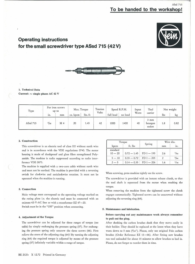
To be handed to the workshop
Operating instructions
for the double insulated and radio suppressed
Electric Screw-Driver type ASs
636,
ASs
636
b
and for type ASs
736,
ASs
736
b
(42
Volts)
1.
Techn
i
cal
data
Current:
""'
(single
phase
AC)
I
for
screws Speed R.P.M.
Ne
t
weight
Type
Input
Output
up
to
I m. I
mm
full load I
A
Ss
636
ASs
736 (42 V)
1/4
6 450
ASs
636b
self
drilling
screws
up
to
1900
ASs
736 b (42 V) 3
ft6
I 4,8
2.
Construction
T
hi
s
sc
r
ew-d
ri
ver
is
an
electric
tool
of
Class
II
w
ith
protective
insulat-
ion
without
earthin
g
conductor
and
is
in
accordance
with
the
VDE
regulations 0740.
Th
e
protective
insulation
is
attained
by
the
shoc
k-
proof
motor
hou
sing
made
of
Polyamide
an
d
by
insulating
th
e arm
a-
tur
e aga
in
st
th
e
pinion.
The
prot
ec
ti
ve
insulation is tested
wit
h
the
prescribed
test
vo
lt
age
of
4000 V.
Th
e machine is radio suppressed
in
accordance w
ith
radio
int
erfe
rence degree
N.
It
is supplied
wi
th
a
t
wo
-cor
e cable w
ithout
eart
hin
g
conductor
and
must
not
be
eart
hed.
Ty
pe
ASs 736
for
low
tension (42 V) is
of
the
same design,
but
with
~
out
double insulation
and
not
radio
s
uppr
essed.
The
machine is
pr
ovi
ded
with
a
rever
s
in
g switch
for
clockwi
se
a
nd
anticlockwise
rot
ation.
It
must
not
be
operated
when
the
machine
is
running.
To
pr
event
the
overbridgi
ng
of
the
in
sulation
no
addit
i
ona
l
mark
in
g
plates
and
signs
must
be
ri
ve
ted
or
screwed
on
the
hou
sin
g.
We
recommend
the
use
of
transfers
only.
3.
Connection
Before
plu
gg
in
g m the tool check
that
vo
lt
age st
ate
d
on
the
rating
plate
is
in
acco
rdance
with
the voltage of t
he
mains
supp
ly.
Switch
must
be
in
the
"Off"
position
when
connecting.
BE
173/e
XEW
11.69
Printed
in
Germany
no
load
Watts
Watts
lb
s I
kg
800
-
..
3.5 1.6
.230
115
3000 3.5 1.6
.230
11
5
4.
Adjustment
of
the
torque
The
machine is
pro
v
ided
w
ith
a positive clutch.
The
torque
is adju
sted
by
changi
ng
the
positi
on
of
the
clut
ch claws;
the
deeper
the
gripping
of
the
claws,
the
higher
the
torque
.
In
order
to
ad
ju
st
the
claws loosen securing screw (56),
then
turn
sc
r
ew
(55).
Moreover, the
torqu
e is depe
nd
e
nt
on
th
e pressure
of
th
e
driver
agai
nst
the
sc
re
w.
5.
Maintenance
Befor
e
carr
y
ing
out
any maintenance
work
al
ways
re
m
ember
to
pull
out
the
plu
g.
Eve
ry 300
dut
y hours
blow
or
brush
out
th
e
tool
with
special a
tt
en
tion
to
car
bon brush ho
ld
ers
and
ins
ulate
d parts
in
orde
r
to
gua
r
antee
the
safety
gi
ven
by
the
protective
insulation.
After
checking
the
carbon
bru
shes m
ake
sure
to
r
efit
them
in
their
original
position
and
check th
at
th
ey
move
easily
in
their
holde
r.
They
sh
ou
ld
be
repla
ced
at
the
latest when
th
ey
h
av
e
worn
do
wn
to
7
mm
(1
/4"). Please,
on
ly use o
ri
ginal
Fein
carbon
brushes.
Aft
er fitting
new brushes,
run
tool
u
nl
oaded
for
a
bout
15
minute
s to
allow
bru
shes
to
bed
in.
One
pair
of
spare
ca
rbon
br
ush
es
w
ill
be
f
ound
in
th
e
cover
of
th
e
hand
le; please, do
not
forget
to
reorder
them
in time.
From
August 1970, gear and ball bearin
gs
are
pr
ovided with
the
special gre
ase
Sst 1. Correct quantity for gear 20 g.
59
63
Connecting
plan
60
61
57
58
38
54
53
52
I I
56
55
43
43a
39
40
41
42
35
S)
~
i
(j(j
(jo
'
..-...--.~
lr-
':.-+-..A
----
,_......
51
37
36
--
J44
49
50
I I I
•
0•
! l j
.~~
-~
I I . - I
=;.,.
1 I l
46
45
I
.-.
___
...
__
J
M
~
~~~
-
___._.
....
~
~--------""'
---------"""'
~--------------
~
I I
"'
I
e-
..
___
____
_
26
L-~®)~
\I,
w
"'"T
--
1 L
64
33
31
32
,.,.----
,.,.,.,...
,.,.,.,.
....
~
~
,.,.,.,.,.,.
15
-~
Reserving
,..
switch I 3
I
------------.:_
Switch
!
I
I
I
13a 12
-----
----
..
4t!"'
......
-----
------
~
/
--
----
1~.
~
3~
--f~
'
~
'I
/
,/?'
,/'
Q
-
~/
~
~
/
23
I
.,.
L-~
A,..,
____
,,
I v'
-·
--"f/
·
L{f
~
14
24/c#'
~
11
distributing
main
Component
Parts
0
z
Ord
er
>..
D
es
cription
....
ry
....
Reference
"'
p..
0
z Order
>..
....
ry
Descri
ption
....
Reference
"'
p..
1-25
MK
1-18-2 1
motor
housing,
assembled
40
LK
1-32 1 ball bearing
with
cable
41
ZR15-16x0,75 1 gear
wh
eel for ASs 636, 46 tee
th
1-15
MK
1-18-1 1 motor housing, assembled
41
ZR15-35x0,75 1 gear
whe
el
for
ASs 636 b, 34 teeth
1
MK
1-18 1 motor housing 42
LK
15-4 1 bearing
2
EZ
1-58 1 switch 43 BF 19-40 1 pressure
pin
FD
1-196 1 spring 43a
FD
1-152 1 compression spring
3
EZ
22-35 1
int
e
rfer
ence capacitor 44
LK
1-1 2 ball bearing
4 EZ 1-59 1 reversing switch 45
LK
6a-11 1 needle cage
5-7
EZ
12-43-1 2 carbon holder, assembled 46
PT
8-153 1
dr
iv
ing
plate
8 EZ 11-59 2 carbon brush 47 ZR16-16x0,75 1 countershaftpinion
for
ASs 636, 9teeth
9
EZ
13-8 2 sliding cover 47 ZR16-19x0,75 1 countershaftpinion
for
ASs 636 b,
10 SR 2-M3,5x12 4 cylindrical screw
21
teeth
11
BF 19-42-1 1 locking pin, assembled
48
ZR
15-13x0,75 1 countershaft gear
whe
el, 30 tee
th
12
state
type
1 pole housing
wi
th
winding
and
volt
age
13 SR 2-M3,5x50 2 cylindrical
sc
re
w
13a
PT
6-M 3,5 2 securing
plate
I14 JS 28-4 1 insulating
ring
15 JS 15-11 1 bolster
16
EZ
7-101 1 cable
I 17 JS 13-7 1 cable protecting sl
ee
ve
18
PT
31
-21 1 cable clamping
br
id
ge
19 SR3-M3,5x10 2 fillister he
ad
screw
20-23
GH
1-
18
-1 1 cover
20-23
GH
1-20-1 1 cover wi
th
bow
24 SR2-M3,5x15 2 cylindrical screw
25
SR6-M3,5x8 1 fillister screw
26
state
tyfce 1
armature
with
wi
nding
and
vo
cage collector
and
fan
49-51
WB
16-4-1 1 countershaft, assembled
49
WB
16-4 1 countershaft
50 ZR15-15x0,75 1 countersh
af
t gear wheel,
31
tee
th
51
ZR15-14x0,75 1 counters
haft
gear wheel,
41
teeth
52 A 4-37 1
tool
holder
53
FD
6-14 1 ball retaining ring
I 54
LK
8-2,5 3 ball
55
SR
18-9 1 setting screw
56 SR 9-M4x8 1 grubscrew I
57
LG
3-14 1 bearing bushing
58
JS 15-9 1 securing
plu
g I
59-63
BU
4-24-1 1 guide bush, assembled
59
BU
4-24 1 guide bush
60
FD
1-90 1 compression spring
61
RJ
2-17 1 lock ring
30
ZR
4-42 1
armature
dri
ve, 6 teeth
31
SR2-M3,5x6 3 cylindrical screw
32
PT
5d
-M3,5 3 securing
plate
33
LK
16-
35
2 ba
ll
bearing
63
FD
6-13-1 1 spring
ri
ng
64
RJ
12-47 1 sealing
rin
g
65 SR2-M3,5x60 2 cylindrical screw
66 SR2-M3,5x
45
2 cylindrical screw
34-63 LA 8-102-2 1
gear
head,
assembled
34-37 LA 6-142-1 1 intermediate bearing, assembled
35
LG
1-94 1 bearing bushing
36
LG
4-3 1 coun
ter
sha
ft
bea
rin
g
37 SR2-M3,5x10 2 cy
lind
rical screw I
38--63 LA 8-102-1 1
outer
bearing, assembled
38 LA 8-102 1 outer bearing
39
WB
8-17 1 cl
aw
sha
ft
I
Parts
for
low
voltage
42
Volts
1-15
MK
1-18-3 1
motor
housing, assembled
16
EZ
6-126 1 c
ab
le
Accessories
BU
81-9,5x
11
1 centering
bu
sh }
further
sizes
Z 81-8x1,2 1 screw
driver
bit
see leaflet Zs 1
Z
81k-2H
1 screw
driver
bit
(ASs 636 b)
21
EZ
11-59 2 c
ar
bon
brush
In
order
to
prevent
accidents
check
cable
at
regular intervals.
To
replace
the
cable
take
off
the
screws (24, 25),
then
take
off the handle
cover t20), loosen the
two
screws (19)
of
the
terminal clamp (18)
and
clamp off
the
cable from the switch (2).
6.
Lubrication
We recommend
to
renew
the
gear grease
after
300
duty
hours. Please,
only
use
the
Fein special grease
FG
12.
For
ball
bearings which should
be lubricated
after
approx. 900
duty
hours
we
recommend
our
ball
bearing grease
FK
3.
The
ball
bearings
are
to
be rinsed in clean solvent
and
packed
with
new
grease.
The
space
between
inner
and
outer
ring
is
to
be
one
third
filled
with
grease
in
order
that
the
bearings
do
not
overheat.
Type
of
grease
FG
12 for gears
FK
3 for ball bearings
Grease tubes
d N
or
er
o.
MZ
60-3/FG
12
MZ
60-2/FK
3
Contents
oz
g
22
/a
80
11/a
40
No
claims
can
be
entertained
for
damage
due
to
negligent
maintenance
and
inadequate
lubrication.
7.
Overhaul
After
900
duty
hours
the
machine should be completely dismantled
as described under
paragraph
8
and
all
parts
should be thoroughly
cleaned. Rinse ball
beari~gs
and
gears
in
clean solvent
and
pack
with
fresh grease
as
per
paragraph
6.
Please
be
sure
that
all
electric
parts
are
only
cleaned
dry.
8.
Dismantling
The
tool should
onl
y be taken
apart
by
an
expert.
1. Unscrew fillister head screw (25)
and
the
two
cylindrical screws
(24),
then
take
off handle cover (20).
2.
Remove supply cable from switch,
draw
out
switch
and
disconnect
motor
cable.
3.
After
unscrewing the screws (10)
dra
w
out
carbon
holder
(5
).
Push

reversing
swith

(4) backwards. Distributi
on
of
connections
se
e con-
necting
plan.
4.
Loosen cylindrical screws (65, 66), remove
outer
bearin
g (
38
)
with
intermediate bearing (34)
and
take
apar
t.
5.
Pull
out
armature
(26), unscrew three screws (31)
and
remove
armature
drive
(30).
6.
Draw
insulation ring (14)
out
of
motor housing (1), unscrew cylin-
drical screws (13)
and
remove pole housing (12).
Re-assemble
in
reverse sequence.
Please
bear
in
mind
that
existing
washers
are
to
be
placed
in
the
right
places.
Their
loss
would
lead
to
damage.
9.
Repair
and
spare
parts
We recommend
our
Fein Service
Stat
ions to
carry
out
all ov
erhau
l a
nd
repair
work
quickly
and
expertly.
Please
quote
Order
Reference
when
ordering
spare
parts
or
send
in
sample
part,
stating
the
type
of
the
machine.
We
draw
your
att
ent
i
on
to
the
need to ca
rry
out
a high vo.
lt
ag
e test
in accordance w
ith
y
our
local regulations (
or
VDE
re
g
ul
a
tio~
0740)
before
taking
a tool i
nto
service after
any
repair
carried
out
by y
our
own
staff.
(

This manual suits for next models

3

Other Fein Power Screwdriver manuals

Fein ASCS4.8 User manual

Fein

Fein ASCS4.8 User manual

Fein ASCM14 User manual

Fein

Fein ASCM14 User manual

Fein SCS4.8-25 User manual

Fein

Fein SCS4.8-25 User manual

Fein ASCD 12-100 User manual

Fein

Fein ASCD 12-100 User manual

Fein ASW18-6 Series User manual

Fein

Fein ASW18-6 Series User manual

Fein ASW 10-6 Setup guide

Fein

Fein ASW 10-6 Setup guide

Fein Handy Master ABS9 User manual

Fein

Fein Handy Master ABS9 User manual

Fein ASW18-6 PC Series User manual

Fein

Fein ASW18-6 PC Series User manual

Fein ASCM 14 Setup guide

Fein

Fein ASCM 14 Setup guide

Fein ASM14-2 PC User manual

Fein

Fein ASM14-2 PC User manual

Fein M55 X User manual

Fein

Fein M55 X User manual

Fein SCT5-40X User manual

Fein

Fein SCT5-40X User manual

Fein SCT 6-25 Quick start guide

Fein

Fein SCT 6-25 Quick start guide

Fein ASse 636 2b Kinetik User manual

Fein

Fein ASse 636 2b Kinetik User manual

Fein ASM14-4 User manual

Fein

Fein ASM14-4 User manual

Fein ASCD 18-1000 W34 Setup guide

Fein

Fein ASCD 18-1000 W34 Setup guide

Fein M55 User manual

Fein

Fein M55 User manual

Fein SCS4.8-25 User manual

Fein

Fein SCS4.8-25 User manual

Fein ASW14-6 Setup guide

Fein

Fein ASW14-6 Setup guide

Fein ABSU 12 User manual

Fein

Fein ABSU 12 User manual

Fein ASW18-6 PC Series User manual

Fein

Fein ASW18-6 PC Series User manual

Fein ASCD18W2 User manual

Fein

Fein ASCD18W2 User manual

Fein SCT 5-40 Quick start guide

Fein

Fein SCT 5-40 Quick start guide

Fein SCT 5-40 U User manual

Fein

Fein SCT 5-40 U User manual

Popular Power Screwdriver manuals by other brands

Ryobi ERGO Original instructions

Ryobi

Ryobi ERGO Original instructions

Makita 6823TP instruction manual

Makita

Makita 6823TP instruction manual

Draper CD36LITH instructions

Draper

Draper CD36LITH instructions

RED ROOSTER RRI-BS9H2 manual

RED ROOSTER

RED ROOSTER RRI-BS9H2 manual

PROFECO 77415 instruction manual

PROFECO

PROFECO 77415 instruction manual

Makita FS2700 instruction manual

Makita

Makita FS2700 instruction manual

Parkside PABSS 3,6Li Operation and safety notes

Parkside

Parkside PABSS 3,6Li Operation and safety notes

Westfalia 85 95 45 Original instructions

Westfalia

Westfalia 85 95 45 Original instructions

Sumake CA10 quick start guide

Sumake

Sumake CA10 quick start guide

Black & Decker SD1000 instruction manual

Black & Decker

Black & Decker SD1000 instruction manual

Hilti SID 2 A12 Original operating instructions

Hilti

Hilti SID 2 A12 Original operating instructions

VONROC S2 CD505DC Original instructions

VONROC

VONROC S2 CD505DC Original instructions

Chicago Pneumatic CP783 Operator's manual

Chicago Pneumatic

Chicago Pneumatic CP783 Operator's manual

Black & Decker VP720 instruction manual

Black & Decker

Black & Decker VP720 instruction manual

Chicago Electric 93690 Assembly and operating instructions

Chicago Electric

Chicago Electric 93690 Assembly and operating instructions

Beta 583 Nstructions for use

Beta

Beta 583 Nstructions for use

Parkside PSF 4.6 A1 Translation of the original instructions

Parkside

Parkside PSF 4.6 A1 Translation of the original instructions

Parkside PBSA 12 C2 Original instructions

Parkside

Parkside PBSA 12 C2 Original instructions

manuals.online logo
manuals.online logoBrands
  • About & Mission
  • Contact us
  • Privacy Policy
  • Terms and Conditions

Copyright 2025 Manuals.Online. All Rights Reserved.