Fein ASse 636 2b Kinetik User manual

ASse 636 - 2b Kinetik
7 210 77
3 41 00 758 06 6
Printed in Germany 07.01
ASse 636 -2b .book Seite 1 Donnerstag, 28. Juni 2001 8:55 08

2
Deutsch
English
Français
Italiano
ederlands
Español
Português
EÏÏËÓÈο
Dansk
orsk
Svenska
Suomi
Magyar
âesky
Slovensky
Polski
На русском
языке
5
9
13
17
21
25
29
33
37
41
45
49
53
57
61
65
74
76
69
ASse 636 -2b .book Seite 2 Donnerstag, 28. Juni 2001 8:55 08

3
43
1
a
b
2
5c
d
ef
ASse 636 -2b .book Seite 3 Donnerstag, 28. Juni 2001 8:55 08

4
0
6 7
B
A
8
B-A
9
B-A-C
C
g
h
ASse 636 -2b .book Seite 4 Donnerstag, 28. Juni 2001 8:55 08

ASse 636 - 2b Kinetik
5
DE
Bedienungsanleitung Schrauber.
Auf einen Blick.
1 Tiefenanschlag
Schra btiefe einstellen.
2 Drehmoment-Einstellschraube
Einstell ng Drehmoment.
3 Schalter
Ein- nd A sschalten (a),
Arretier ng für Da erla f (b).
4 Umschaltung Rechtslauf oder Linkslauf
Im Stillstand mschalten.
5 Mitgeliefertes Zubehör
Tiefenanschlag (c),
Magnetbithalter (d),
Einsatz 1/4" für Kre zschlitzschra -
ben Phillips Form H Größe 2 mit
Sta bsch tzring (e),
Stiftschlüssel (f).
Zu Ihrer Sicherheit.
Vor Gebra ch dieses Gerätes lesen
nd danach handeln:
diese Bedien ngsanleit ng,
die beiliegenden Sicherheitshinweise
(Schriftenn mmer 3 41 30 054 06 1),
die einschlägigen nationalen Arbeits-
sch tzbestimm ngen.
Diese Bedien ngsanleit ng nd die beilie-
genden Sicherheitshinweise sind z m spä-
teren Gebra ch a fz bewahren nd bei
einer Weitergabe oder Verä ßer ng dem
Gerät beiz legen.
Bestimmungsgemäße Verwendung.
Dieses Gerät ist bestimmt:
für den gewerblichen Einsatz in Ind strie
nd Handwerk,
z m Ein- nd A sdrehen von Schra ben,
speziell für den Einsatz im Trockenba mit
Schnellba schra ben nd Selbstbohr-
schra ben.
Die Verschra b ngen sind mit Tiefen-
anschlag a sz führen.
Sicherheitshinweise.
Verletzungsgefahr
Gerät g t festhalten.
N r mit nbeschädigtem Einsatz arbeiten.
Vorsicht vor verdeckt liegenden elektri-
schen Leit ngen, Gas- nd Wasserrohren:
Den Arbeitsbereich z. B. mit einem
Metallort ngsgerät kontrollieren.
Keine Schilder nd Zeichen a f das Gerät
nieten oder schra ben. Die Sch tzisolie-
r ng kann dad rch nwirksam werden.
Empfohlen werden Klebeschilder.
N r nbeschädigte Stecker nd Kabel
verwenden.
Sachbeschädigung
Netzspann ng nd Spann ngsangabe am
Gerät müssen übereinstimmen.
Persönliche Schutzausrüstung.
Beim Arbeiten mit diesem Gerät folgende
Sch tza srüst ng tragen:
festes Sch hwerk, Haarnetz (bei langen
Haaren).
!
!
ASse 636 -2b .book Seite 5 Donnerstag, 28. Juni 2001 8:55 08

6
ASse 636 - 2b Kinetik
DE
Bedienen.
Ein- und Ausschalten (3).
■
Z erst Kabel nd Stecker a f Beschädi-
g ngen prüfen.
Einschalten:
■
Schalter (a) drücken. Drehzahl je nach
Eindrücktiefe des Schalters.
A sschalten:
■
Z m A sschalten Schalter loslassen.
Arretieren für Da erla f:
■
Bei ganz gedrücktem Schalter (a)
(= maximale Drehzahl) Arretier-
knopf (b) drücken.
■
Z m Entriegeln Schalter (a) nochmals
drücken nd loslassen.
Drehrichtung wählen (4).
■
Drehricht ng an Schalter a f Rechtsla f
oder Linksla f stellen.
Betätigung nur im Stillstand des Motors.
Einsatz wechseln.
Verletzungsgefahr
durch unbeabsichtigtes Einschalten.
Vor dem Wechseln Stecker ziehen.
■
Tiefenanschlag (1) mit Drehbeweg ng
abziehen.
■
Einsatz entnehmen.
■
Ne en Einsatz einrasten.
■
Tiefenanschlag (1) mit Drehbeweg ng
a fsetzen.
Drehmoment einstellen.
Das Gerät ist mit einer Einfach-Kla en-
k ppl ng a sgerüstet. Das Drehmoment
kann d rch das Verstellen der Eingrifftiefe
der K ppl ngskla e verändert werden.
Großer Kla eneingriff ergibt großes
Drehmoment nd kleiner Kla eneingriff
ergibt kleines Drehmoment.
Eingestellt wird d rch Drehen der Dreh-
moment-Einstellschra be (2).
■
Lagerhülse abschra ben nd Gewin-
destift entfernen.
■
Drehmoment-Einstellschra be (2) in
gewünschte Richt ng drehen.
Rechtsdrehen der Schra be in die fol-
gende Kerbe erhöht den Eingriff m
0,16 mm. Die Eingrifftiefe ist vom Werk
a f ca. 0,75 mm eingestellt.
■
Lagerhülse a fschra ben (10–12 Nm).
Das Drehmoment ist abhängig von der
Kraft, mit der die Maschine gegen die
Schra be gedrückt wird.
Tiefenanschlag einstellen (6-9).
Verletzungsgefahr
durch unbeabsichtigtes Einschalten.
Vor dem Einstellen Stecker ziehen.
Der Tiefenanschlag besteht a s Überw rf-
hülse (g) nd Anschlaghülse (h). Eine
ganze Umdreh ng der Anschlaghülse
(viermaliges Ratschen) verändert die
Schra btiefe m 1 mm.
■
Tiefenanschlag (1) mit Drehbeweg ng
a fsetzen.
■
Als Voreinstell ng die Anschlaghülse so
einstellen, dass sie mit der A flageflä-
che der Schra be eine Ebene bildet.
■
Eine Schra be z r Probe bis z m
Anschlag eindrehen.
!!
ASse 636 -2b .book Seite 6 Donnerstag, 28. Juni 2001 8:55 08

ASse 636 - 2b Kinetik
7
DE
■
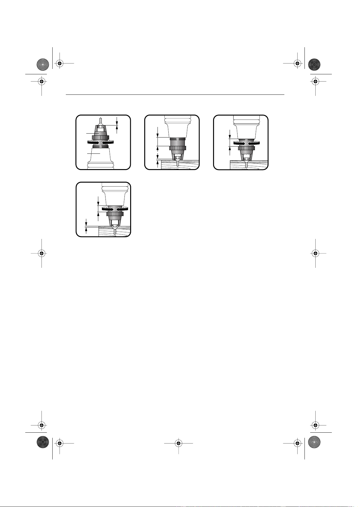
Schra btiefe korrigieren.
Soll die Schra be tiefer eingedreht
werden, die Anschlaghülse hineindre-
hen. Ist die Schra be z tief eingedreht,
die Anschlaghülse hera sdrehen.
Beispiel: Schra be steht nach erster Ver-
schra b ng noch 1,5 mm a s dem Mate-
rial hera s. Anschlaghülse m
1,5 Umdreh ngen hineindrehen, m kor-
rekte Einschra btiefe z erreichen.
Reinigen und Pflegen.
Verletzungsgefahr
durch unbeabsichtigtes Einschalten.
Vor Pflegearbeiten Stecker ziehen.
Einmal pro Woche, bei hä figem
Gebra ch öfter d rchführen:
■
Kühll ftöffn ngen reinigen.
■
Motorra m von a ßen mit trockener
Dr ckl ft a sblasen.
Warten und Reparieren.
Verletzungsgefahr
Warten, prüfen und reparieren dürfen nur
Elektrofachkräfte nach den im je eiligen
Land gültigen Vorschriften.
Zum Warten und Reparieren.
Wir empfehlen nsere K ndendienstab-
teil ng (Zentralreparat r), FEIN-Vertrags-
werkstätten nd -Vertret ngen. Adressen
am Ende dieser Bedien ngsanleit ng nd
in den beiliegenden Sicherheitshinweisen.
Diese Bedien ngsanleit ng der Reparat r-
werkstatt mitgeben. Ersatzteilübersicht
am Ende dieser Bedien ngsanleit ng.
Elektrofachkräften senden wir a f Anfor-
der ng eine Reparat ranleit ng z .
N r Original-FEIN-Ersatzteile verwen-
den.
Ersatzteile.
Ersatzteilübersicht am Ende dieser
Bedien ngsanleit ng. Teile-Nr. (1),
Bestelln mmer (2) sowie Anzahl der
Ersatzteile (3) erleichtern das Bestellen.
Zubehör.
Bildliche Darstell ng nd Bestelln mmern
am Ende dieser Anleit ng.
Erlä ter ngen z m Z behör:
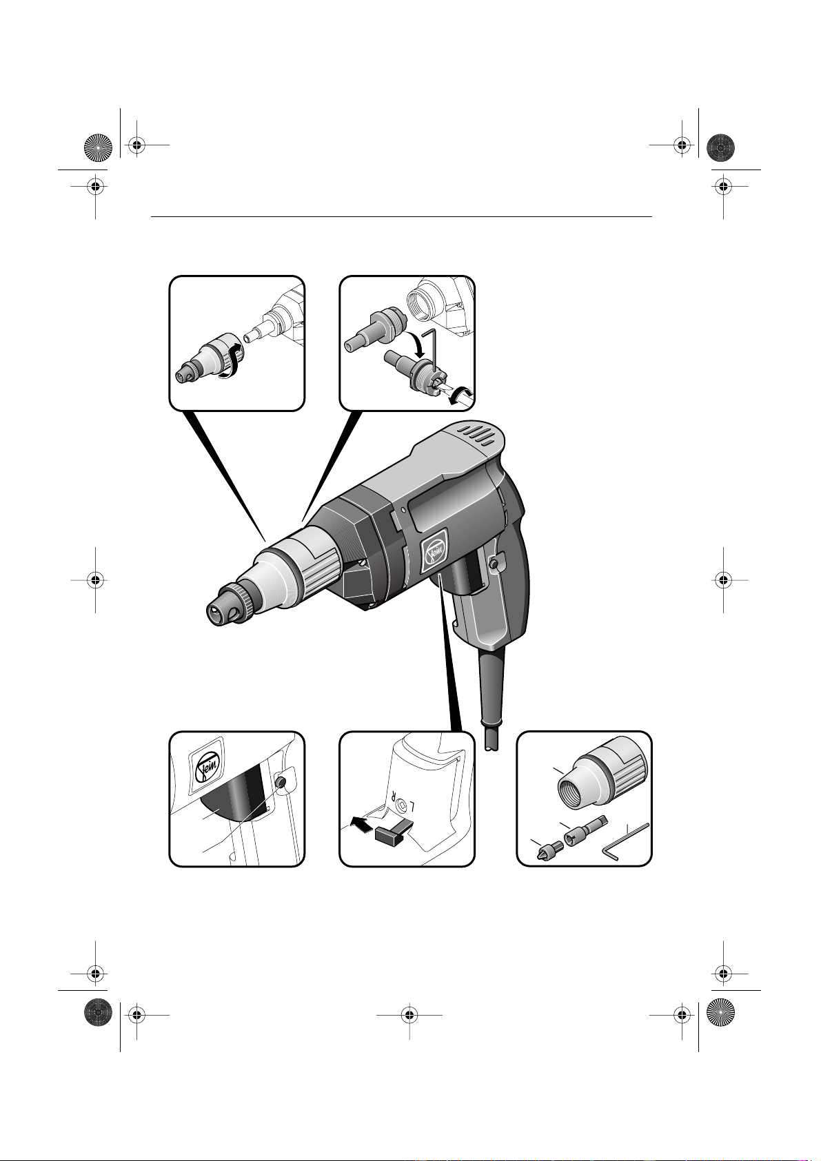
A Tiefenanschlag, z sammengesetzt a s
Überw rfhülse nd Anschlaghülse.
B Verschiedene Einsätze,
Schaft 1/4" Sechskant
(PZ = Pozidriv, Ph = Phillips,
TX = Torx, SW = Schlüsselweite
Sechskant).
C Werkze gkoffer, Metall
(390 x 240 x 110 mm).
D Werkze gkoffer, K nststoff
(305 x 265 x 90 mm).
Garantie.
Für FEIN-Geräte leisten wir Garantie
gemäß den gesetzlichen nd länderspezifi-
schen Bestimm ngen (Nachweis d rch
Rechn ng oder Lieferschein).
Schäden, die d rch nsachgemäße
Behandl ng, Überlast ng oder normale
Abn tz ng entstanden sind, bleiben von
der Garantie a sgeschlossen.
Bitte wenden Sie sich an nsere K nden-
dienstabteil ng (Zentralreparat r), FEIN-
Vertragswerkstätten oder -Vertret ngen.
!
!
ASse 636 -2b .book Seite 7 Donnerstag, 28. Juni 2001 8:55 08

8
ASse 636 - 2b Kinetik
DE
Umweltschutz.
Verpack ngen, a sgediente Geräte nd
Z behör einer mweltgerechten Wieder-
verwert ng z führen.
Weitere Informationen erhalten Sie bei
Ihrem Fachhändler.
Technische Daten.
Der A-bewertete Schalldr ckpegel des
Gerätes beträgt typischerweise 78 dB (A).
Der Gerä schpegel beim Arbeiten kann
85 dB (A) überschreiten.
Gehörsch tz tragen!
Die Hand-Arm-Vibration ist typischer-
weise niedriger als 2,5 m/s
2
.
Messwerte ermittelt nach EN 50 144.
CE-Konformität.
Wir erklären in alleiniger Verantwort ng,
dass dieses Prod kt mit den folgenden
Normen oder normativen Dok menten
übereinstimmt: EN 50 144, EN 55 014,
EN 61 000-3-2/-3-3 gemäß den Bestim-
m ngen der Richtlinien 98/37/EG nd
89/336/EWG.
C. & E. FEIN GmbH & Co. KG,
Postfach 10 14 44 • 70013 St ttgart
Bei Veränder ng des Gerätes verliert
diese Erklär ng ihre Gültigkeit nd die
Garantie erlischt.
Bestelln mmer 7 210 77
Ba art ASse 636-2b
Kinetik
Nenna fnahme 320 W
Leist ngsabgabe 160 W
Lastdrehzahl 0 – 2100/min
Leerla fdrehzahl 0 – 3500/min
max. Anziehdrehmo-
ment bei hartem
Schra bfall 12 Nm
Gewicht 1,4 kg
Werkze ga fnahme 7 mm mit Angel
DIN 3126-H7
Innenflachkant
Bender Peltz
ASse 636 -2b .book Seite 8 Donnerstag, 28. Juni 2001 8:55 08

ASse 636 - 2b Kinetik
9
EN
Operating instructions for screwdriver.
Overview.
1 Bit stop
Setting the screwing depth.
2 Torque adjusting key
For setting the torq e.
3 Switch
Switching ON/OFF (a),
Locking for contin o s mode (b).
4 Selector switch for clockwise and
anti-clockwise rotation.
Select when power tool is at a
standstill.
5 Supplied accessories
Depth stop (c).
Magnetic holder (d) for bits.
Bit 1/4" for Phillips screws size 2,
Form H with d st protection ring (e).
Wrench (f).
For your safety.
Before sing this power tool, read
and comply with:
these operating instr ctions,
the enclosed safety instr ctions
(doc ment n mber 3 41 30 054 06 1),
the relevant national ind strial safety
reg lations.
These operating instr ctions and the
enclosed safety information sho ld be
kept caref lly for later se and enclosed
with the machine, sho ld it be passed on
or sold.
Intended use.
This power tool is intended for:
commercial se in ind stry and trade,
for screwdriving and removing screws,
specially for se in dry wall constr ction
with fast dry-wall screws and self-drilling
screws.
Screwing sho ld be carried o t sing the
bit stop.
Safety instructions.
Risk of injury
Hold the power tool firmly.
Only work with ndamaged insert.
Beware of any concealed electric cables,
gas or water cond its; check the working
area with a metal detector, for example.
Do not rivet or screw any name-plates or
signs onto the power tool. The protective
ins lation can thereby be rendered inef-
fective. Adhesive labels are recom-
mended.
Only se an ndamaged pl g and cable.
Damage to property/material
Mains voltage m st correspond with the
voltage specifications on the power tool.
Personal protective equipment.
When sing this power tool wear the fol-
lowing protective items:
st rdy shoes, hair net (for long hair).
!
!
ASse 636 -2b .book Seite 9 Donnerstag, 28. Juni 2001 8:55 08

10
ASse 636 - 2b Kinetik
EN
Operating the power tool.
Switching O /OFF (3).
■
First check that the cable and pl g are
not damaged.
Switching the power tool ON:
■
Press switch (a). Speed according to
how far the switch is pressed in.
Switching the power tool OFF:
■
To t rn off, release switch.
Locking for contin o s mode:
■
When the switch (a) is f lly pressed in
(= maxim m speed) press the locking
b tton (b).
■
To release, press switch (a) again and
then let go.
Select direction of rotation (4).
■
Set the direction of rotation sing
selector switch for clockwise and anti-
clockwise rotation.
Only operate when power tool is at a
standstill.
Changing the insert.
Risk of injury
by s itching the tool ON unintentionally.
Before changing the tool, pull out the mains
plug.
■
P ll of the bit stop (1) with a t rning
movement.
■
Remove the insert.
■
Notch in a new insert.
■
Mo nt the bit stop (1) sing a t rning
movement.
Adjusting the torque.
The power tool is fitted with a single jaw
cl tch co pling. The torq e can be
changed by adj sting the depth engage-
ment of the cl tch.
A greater depth of engagement prod ces
a greater torq e and a lesser depth a
smaller/lower torq e.
The adj stment is carried o t by t rning
the torq e adj sting key (2).
■
Unscrew the bearing sleeve and
remove the screwed pin.
■
T rn the torq e adj sting key (2) in the
desired direction.
T rning the screw/key clockwise to the
next notch will increase the depth engage-
ment by 0.16 mm. The depth engagement
is pre-set at the factory to approx.
0.75 mm.
■
Unscrew the bearing sleeve
(10 – 12 Nm).
The torq e is dependent pon the force at
which the power tool is pressed against
the screw.
Setting the bit stop (6-9).
Risk of injury
by s itching the tool ON unintentionally.
Before adjusting, pull out the mains plug.
The bit stop consists of a connecting col-
lar (g) and a stop collar (h). One f ll t rn
of the stop collar (fo r notching intervals)
changes the screwing depth by 1 mm.
■
Mo nt the bit stop (1) sing a t rning
movement.
■
As a preliminary setting, set the stop
collar s ch that it is fl sh with the s r-
face of the screw.
■
Screw in one sample screw as far as the
stop.
!!
ASse 636 -2b .book Seite 10 Donnerstag, 28. Juni 2001 8:55 08

ASse 636 - 2b Kinetik
11
EN
■
Correct the screwing depth.
If the screw is to be screwed in deeper,
screw in the stop collar f rther. If the
screw is screwed in too deeply,
nscrew the collar stop accordingly.
Example: After being screwed in for the
first time, the screw is still projecting
1.5 mm from the material. T rn in the
stop collar 1.5 t rns to reach the correct
screwing depth.
Cleaning and care.
Risk of injury
by s itching the tool ON unintentionally.
Before cleaning, pull out the mains plug.
Carry o t the following once a week, or
more often if the power tool is sed more
freq ently:
■Clean the venting openings.
■Blow o t the motor space from o tside
with dry compressed air.
Maintenance and repairs.
Risk of injury
Service, testing and repairs may only be car-
ried out by electrical engineers in conformity
ith the regulations valid in the respective
country.
Maintenance and repairs.
We recommend o r c stomer service
department (repair centre), FEIN a thor-
ized service centres and agencies.
Addresses can be fo nd at the end of
these operating instr ctions and in the
enclosed safety instr ctions.
Please hand these operating instr ctions
to the repair centre. An overview of spare
parts can be fo nd at the end of these
operating instr ctions.
Upon req est a repair man al is sent to
the electrical engineers.
Only se original FEIN spare parts.
Spare parts.
The overview of spare parts is at the end
of these operating instr ctions. Q oting
the parts no. (1), order no. (2) as well as
the n mber of spare parts (3) facilitates
the ordering proced re.
Accessories.
Ill strations and order n mbers can be
fo nd at the end of these instr ctions.
Description of the accessories:
A The bit stop consists of the connecting
collar and stop collar.
B Different inserts,
shaft 1/4" hexagon
(PZ = Pozidriv, Ph = Phillips,
TX = Torx, SW = width across flats,
hexagon).
C Metal carry case
(390 x 240 x 110 mm).
D Carry case, plastic
(305 x 265 x 90 mm).
Guarantee.
FEIN power tools are g aranteed in
accordance with stat tory and national
reg lations (evidence of p rchase by
invoice or delivery note).
Damage ca sed by improper handling,
overload or normal wear shall be
excl ded from the g arantee.
Please contact o r c stomer service
(repair centre), FEIN a thorized service
centres or agencies.
!
!
ASse 636 -2b .book Seite 11 Donnerstag, 28. Juni 2001 8:55 08

12
ASse 636 - 2b Kinetik
EN
Environmental protection.
Packaging, worn o t power tools and
accessories sho ld be recycled.
F rther information is available from yo r
dealer.
Specifications.
The A-weighted so nd press re level of
the power tool is typically 78 dB (A).
D ring operation of the power tool the
noise level may exceed 85 dB (A).
Wear ear protection!
The hand/arm vibration is typically less
than 2.5 m/s2.
Meas red val es are determined accord-
ing to EN 50 144.
CE conformity.
We declare o rselves solely responsible
for this prod ct conforming with the fol-
lowing standards or standardized doc -
ments: EN 50 144, EN 55 014,
EN 61 000-3-2/-3-3 in accordance with
the reg lations in the recommendations
98/37/EC and 89/336/EEC.
C. & E. FEIN GmbH & Co. KG,
Postfach 10 14 44 • 70013 St ttgart
Any alterations made to the power tool
shall render this declaration invalid and
the g arantee shall become ineffective.
Order n mber 7 210 77
Type ASse 636-2b
Kinetik
Rated inp t 320 W
O tp t 160 W
On-load speed 0 – 2100 rpm
No-load speed 0 – 3500 rpm
max. tightening torq e
for hard material 12 Nm
Weight 1.4 kg
Tool receptacle 7 mm with hinge
DIN 3126-H7
with internal flat
Bender Peltz
ASse 636 -2b .book Seite 12 Donnerstag, 28. Juni 2001 8:55 08

ASse 636 - 2b Kinetik
13
FR
otice d’utilisation, visseuse.
Vue générale.
1 Butée de profondeur
Réglage de la profonde r de vissage.
2 Vis de réglage du couple
Réglage d co ple.
3 Interrupteur Marche/Arrêt
Mise en marche et arrêt (a),
Blocage po r marche permanente (b).
4 Commutation du sens de rotation
Ne comm ter le sens de rotation q ’à
l’arrêt total de l’appareil.
5 Accessoires fournis
B tée de profonde r (c),
Porte-embo t aimanté (d),
Insert 1/4" po r vis à empreinte cr ci-
forme Phillips, forme H, taille 2, avec
bag e anti-po ssières (e),
Clé mâle co dée po r vis à six pans (f).
Pour votre sécurité.
Avant d’ tiliser cet appareil, lire et
respecter scr p le sement :
la présente notice d’ tilisation,
les conseils de séc rité ci-joints
(réf. doc ments 3 41 30 054 06 1),
les dispositions concernant la prévention
des accidents d travail en vig e r dans le
pays en q estion.
Bien garder ces instr ctions d’ tilisation
ainsi q e les conseils de séc rité ci-joints
en v e d’ ne tilisation ltérie re ; ils doi-
vent être joints à l’appareil en cas de trans-
mission o de vente à ne tierce
personne.
Utilisation conforme à la
destination.
Cet appareil a été conç :
po r être mis en œ vre dans les métiers
de l’ind strie et de l’artisanat,
po r le vissage et le dévissage des vis, pl s
partic lièrement de vis rapides et vis a to-
fore ses dans les cloisons en placoplâtre.
Effect er les vissage à l’aide de la b tée de
profonde r.
Consignes de sécurité.
Risques de blessures
Maintenir l’appareil fermement.
Ne travailler q ’avec n embo t q i n’est
pas endommagé.
Faire attention a x cond cte rs électri-
q es, cond ites de gaz et d’ea po vant
être cachés : contrôler l’endroit de travail
à l’aide d’ n détecte r de méta x par
exemple.
Ne pas riveter ni visser de plaq es o de
repères s r l’appareil. Vo s risq eriez
sinon de rendre inopérante la do ble iso-
lation de l’appareil. Il est recommandé
d’ tiliser des a tocollants.
Utiliser niq ement ne fiche et n câble
en bon état.
Détérioration du matériel
La tension d secte r doit correspondre à
celle mentionnée s r l’appareil.
Equipements de protection
individuelle.
Pendant les trava x avec cet appareil, por-
ter l’éq ipement de protection s ivant :
cha ss res solides, filet à cheve x
(po r cheve x longs).
!
!
ASse 636 -2b .book Seite 13 Donnerstag, 28. Juni 2001 8:55 08

14
ASse 636 - 2b Kinetik
FR
Utilisation.
Mise en marche et arrêt (3).
■Vérifier d’abord q e le câble d’alimen-
tation et la fiche sont en parfait état.
Mise en marche :
■Enfoncer l’interr pte r M/A (a). La
vitesse de rotation varie selon la pres-
sion exercée s r l’interr pte r.
Arrêter :
■Po r arrêter l’appareil, relâcher l’inter-
r pte r Marche/Arrêt.
Blocage po r marche permanente :
■Après avoir app yé à fond s r l’inter-
r pte r (a) (= vitesse de rotation maxi-
male), app yer s r le bo ton de
blocage (b).
■Afin de débloq er, app yer de no -
vea s r l’interr pte r (a) et le relâ-
cher.
Commutation du sens de
rotation (4).
■A l’aide d comm tate r, régler le sens
de rotation de l’appareil s r rotation à
droite o rotation à ga che.
e commuter qu’à l’arrêt total du moteur.
Changement de l’embout.
Risques de blessures
pouvant survenir en cas d’une mise en mar-
che non intentionnée.
Avant tout changement d’outil, débrancher la
fiche de la prise de courant.
■Retirer la b tée de profonde r (1) par
n mo vement de rotation.
■Enlever l’embo t.
■Faire encliq eter le no vel embo t.
■Monter la b tée de profonde r (1) par
n mo vement de rotation.
Réglage du couple.
L’appareil est éq ipé d’ n acco plement
simple à griffes. Le co ple pe t être modi-
fié en réglant la profonde r de prise des
griffes de l’acco plement.
Une profonde r de prise importante des
griffes entraîne n co ple élevé, ne faible
profonde r de prise des griffes entraîne
n co ple réd it.
Le réglage s’effect e en to rnant la vis de
réglage d co ple (2).
■Dévisser la do ille et enlever la cheville
filetée.
■To rner la vis de réglage d co ple (2)
dans le sens désiré.
Un mo vement de rotation de la vis vers
la droite j sq ’à l’entaille s ivante a g-
mente la prise de 0,16 mm. La profonde r
de prise a été réglée à l’ sine à environ
0,75 mm.
■Visser la do ille (10 – 12 Nm).
Le co ple dépend de la force avec laq elle
l’appareil est pressé contre la vis.
Réglage de la butée de profondeur
(6-9).
Risques de blessures
pouvant survenir en cas de mise en marche
non intentionnée.
Avant tout réglage, débrancher la fiche de la
prise de courant.
La b tée de profonde r se compose d’ ne
do ille-chapea (g) et d’ ne do ille de
b tée (h) Un to r complet de la do ille de
b tée (q atre déclics) modifie la profon-
de r de vissage de 1 mm.
■Monter la b tée de profonde r (1) par
n mo vement de rotation.
■Régler dans n premier temps la do ille
de b tée de sorte q ’elle constit e n
se l nivea avec la s rface assise de la
vis.
!
!
ASse 636 -2b .book Seite 14 Donnerstag, 28. Juni 2001 8:55 08

ASse 636 - 2b Kinetik
15
FR
■Visser ne vis à fond à titre d’essai.
■Corriger la profonde r de vissage.
Si la vis doit être vissée pl s profondé-
ment, visser la do ille de b tée. Si la vis
est vissée trop profondément, dévisser
la do ille de b tée.
Exemple : Une fois le premier vissage
effect é, la vis dépasse encore le matéria
de 1,5 mm. Visser la do ille de b tée d’ n
to r et demi afin d’atteindre la bonne pro-
fonde r de vissage.
ettoyage et entretien.
Risques de blessures
pouvant survenir en cas d’une mise en mar-
che non intentionnée.
Avant tous travaux d’entretien et de nettoya-
ge, débrancher la fiche de la prise de courant.
A effect er ne fois par semaine, o pl s
so vent en cas d’ tilisation fréq ente :
■Nettoyer les o ïes de ventilation.
■Nettoyer le compartiment mote r de
l’extérie r en y so fflant de l’air com-
primé sec.
Entretien et réparation.
Risques de blessures
Faire effectuer l’entretien, le contrôle et les
réparations de l’appareil uniquement par un
électricien respectant les prescriptions en vi-
gueur dans le pays respectif.
Consignes d’entretien et de
réparation.
No s vo s recommandons de vo s adres-
ser à notre Service après-vente (centre de
réparation), a x ateliers agréés FEIN ainsi
q ’a x représentants FEIN. Vo s tro ve-
rez le r adresse à la fin de la présente
notice d’ tilisation et dans les consignes
de séc rité ci-jointes.
Remettre la présente notice d’ tilisation à
l’atelier chargé des réparations. Vo s
tro verez n récapit latif des pièces de
rechange à la fin de cette notice d’ tilisa-
tion.
No s faisons parvenir ne notice de répa-
ration a x électriciens s r demande.
Utiliser niq ement des pièces de
rechange FEIN d’origine.
Pièces de rechange.
Vo s tro verez n récapit latif des pièces
de rechange à la fin de cette notice d’ tili-
sation. Le n méro de la pièce (1), la réfé-
rence (2) ainsi q e le nombre de
pièces (3) facilitent la commande.
Accessoires.
Les ill strations et les n méros de réfé-
rence fig rent à la fin de la présente notice
d’ tilisation.
Note explicative s r les accessoires :
A B tée de profonde r composée d’ ne
do ille-chapea et d’ ne do ille de
b tée.
B Différents embo ts,
tige 1/4" six pans
(PZ = Pozidriv, Ph = Phillips,
TX = Torx, SW = Taille d’o vert re
six pans).
C Coffret à o tils, métal
(390 x 240 x 110 mm).
D Coffret à o tils, matière plastiq e
(305 x 265 x 90 mm).
!
!
ASse 636 -2b .book Seite 15 Donnerstag, 28. Juni 2001 8:55 08

16
ASse 636 - 2b Kinetik
FR
Garantie.
Notre garantie co vre les appareils FEIN
conformément a x dispositions légales en
vig e r dans le pays respectif (la fact re
servant de pre ve d’achat).
Cette garantie correspond à n emploi
normal de l’appareil et excl t les avaries
d es à n ma vais sage, à n entretien
défect e x o à l’ s re normale.
Ve illez vo s adresser à notre Service
après-vente (centre de réparation), a x
ateliers agréés o a x représentants FEIN.
Respect de l’environnement.
Rapporter les emballages, les appareils
hors d’ sage et les accessoires à n centre
de recyclage respectant les directives con-
cernant la protection de l’environnement.
Po r pl s de précisions, ve illez vo s
adresser à votre revende r spécialisé.
Caractéristiques techniques.
Les mes res réelles (A) d nivea de pres-
sion aco stiq e de l’appareil sont de
78 dB (A). Lors d travail, le nivea
sonore pe t dépasser 85 dB (A).
Porter ne protection aco stiq e !
Les vale rs de vibration main-bras sont
normalement inférie res à 2,5 m/s2.
Les vale rs de mes re ont été détermi-
nées conformément à la norme e ro-
péenne EN 50 144.
Déclaration de conformité CE.
No s déclarons so s notre propre res-
ponsabilité q e ce prod it est en confor-
mité avec les normes o doc ments
normatifs s ivants : EN 50 144,
EN 55 014, EN 61 000-3-2/-3-3 confor-
mément a x dispositions fig rant dans les
directives 98/37/CE et 89/336/CEE.
C. & E. FEIN GmbH & Co. KG,
Postfach 10 14 44 • 70013 St ttgart
To te modification apportée à l’appareil
fait perdre to te validité à la présente
déclaration ainsi q e le bénéfice de la
garantie.
Référence 7 210 77
Type ASse 636-2b
Kinetik
P issance absorbée 320 W
P issance débitée 160 W
Vitesse de rotation
so s charge 0 – 2100 tr/min
Vitesse à vide 0 – 3500 tr/min
Co ple de vissage max.
en cas de vissage d r 12 Nm
Poids 1,4 kg
Porte-o til 7 mm Avec fixa-
tion de centrage
DIN 3126-H7,
empreinte
femelle à
embo t carré
Bender Peltz
ASse 636 -2b .book Seite 16 Donnerstag, 28. Juni 2001 8:55 08

ASse 636 - 2b Kinetik
17
IT
Istruzioni per l’uso Cacciavite/avvitatore.
Guida rapida.
1 Battuta profondità
Impostare la profondità di avvita-
mento.
2 Vite di regolazione del momento tor-
cente
Impostazione del momento torcente.
3 Interruttore
Accensione e spegnimento (a),
Arresto per f nzionamento conti-
n o (b).
4 Inversione del senso di rotazione
Comm tare a trapano fermo.
5 Accessori a corredo
Dispositivo di batt ta di profondità (c),
Porta tensile magnetico per
inserti (d),
Inserto da 1/4" per viti con testa a
croce Phillips Forma H Grandezza 2
con anello antipolvere (e),
Chiave a br gola (f).
Per la Vostra sicurezza.
Utilizzare l’apparecchio solo dopo
avere letto:
q esto libretto d’istr zioni per l’ so,
le accl se istr zioni di sic rezza
(codice p bblicazione 3 41 30 054 06 1),
le norme nazionali in vigore concernenti
la sic rezza s l lavoro.
Le presenti Istr zioni per l’ so e le accl se
Istr zioni per la sic rezza devono essere
conservate sia per tenerle disponibili
anche in n s ccessivo periodo che per
consegnarle insieme alla macchina in caso
q esta dovesse essere ced ta ad altre per-
sone.
Uso regolare.
Q esto apparecchio è destinato:
per tilizzo a livello professionale sia nel
campo ind striale che in q ello artigianale,
nel campo delle costr zioni a secco per
avvitare e svitare viti di impiego specifico,
sia a fissaggio rapido che di tipo a tofo-
rante.
Le avvitat re devono essere eseg ite ti-
lizzando la batt ta di profondità.
Raccomandazioni per la sicurezza.
Pericolo di ferirsi
Tenere la macchina ben ferma.
Operare escl sivamente con bit intatti.
Attenzione a linee elettriche nascoste ed a
t bazioni del gas e dell’acq a invisibili:
controllare la zona di operazione tiliz-
zando p. es. n rilevatore di metalli.
Non applicare all’apparecchio targhette e
simboli per mezzo di rivetti o viti. Ciò
potrebbe rendere inefficace l’isolamento
di sic rezza. Si consigliano targhette ade-
sive.
Controllare che cavo e spina non siano
danneggiati.
Pericolo di danneggiare l’apparecchio
La tensione di rete deve coincidere con
q anto indicato s i dati di targa riportati
s ll’apparecchio.
Abbigliamento protettivo.
Nei lavori con q esto apparecchio, sare il
seg ente abbigliamento di protezione:
calzat re resistenti, reticella per i capelli
(in caso di capelli l nghi).
!
!
ASse 636 -2b .book Seite 17 Donnerstag, 28. Juni 2001 8:55 08

18
ASse 636 - 2b Kinetik
IT
Uso.
Avviare ed arrestare
l’apparecchio (3).
■Prima dell’avviamento controllare
l’integrità del cavo e della spina.
Avvio:
■Premere l’interr ttore (a). Velocità di
rotazione a seconda della pressione
s ll'interr ttore.
Arresto:
■Per arrestare l’apparecchio, rilasciare
l’interr ttore.
Arresto per f nzionamento contin o:
■Ad interr ttore completamente pre-
m to (a) (= n mero massimo di giri)
premere il p lsante di bloccaggio (b).
■Per sbloccare premere di n ovo e poi
rilasciare l’interr ttore (a).
Selezionare il senso di rotazione (4).
■Agendo s ll’apposito comm tatore
impostare la rotazione destrorsa
opp re sinistrorsa.
Azionare solo quando il motore è fermo.
Cambio dell’utensile ad innesto.
Pericolo di ferirsi
pericolo di infortuni a causa di un’accensione
accidentale.
Estrarre la spina dalla presa di corrente
prima di sostituire l’utensile.
■Estrarre la batt ta di profondità (1)
eseg endo n movimento rotatorio.
■Estrarre il bit ad innesto.
■Innestare in posizione il bit ad innesto.
■Applicare la batt ta di profondità (1)
eseg endo n movimento rotatorio.
Impostazione del momento torcente.
La macchina è dotata di na semplice fri-
zione a denti frontali. Il momento tor-
cente p ò essere modificato spostando la
distanza tra ingranaggio e dente d'innesto.
Con na presa maggiore si ha n
momento torcente alto e con na presa
minore si ha n momento torcente basso.
La registrazione avviene r otando la vite
di regolazione del momento torcente (2).
■Svitare la boccola c scinetto e rim o-
vere il perno filettato.
■R otare la vite di regolazione del
momento torcente (2) nella direzione
che si desidera.
R otando la vite s lla tacca s ccessiva, la
presa a menta di 0,16 mm. La profondità
di presa è regolata di fabbrica s
ca. 0,75 mm.
■Svitare la boccola c scinetto
(10 – 12 Nm).
Il momento torcente dipende dalla forza
con c i la macchina viene prem ta contro
la vite.
Regolare la battuta di profondità
(6-9).
Pericolo di ferirsi
a causa di un’accensione accidentale.
Sconnettere la spina dalla presa di corrente
prima di procedere alla regolazione.
La batt ta di profondità è composta da
b ssola a risvolto (g) e b ssola di bat-
t ta (h). Una rotazione completa della
b ssola di batt ta (q attro scatti) modifica
la profondità di avvitamento di 1 mm.
■Applicare la batt ta di profondità (1)
eseg endo n movimento rotatorio.
■Preregolare la b ssola di batt ta in
modo tale che arrivi a formare n nico
piano con la s perficie di appoggio della
vite.
!!
ASse 636 -2b .book Seite 18 Donnerstag, 28. Juni 2001 8:55 08

ASse 636 - 2b Kinetik
19
IT
■Avvitare na vite per prova fino alla
batt ta di g ida.
■Correggere la profondità di avvita-
mento.
Se la vite deve essere avvitata più in
profondità, avvitare la b ssola di bat-
t ta. Se la vite viene avvitata troppo in
profondità, svitare la b ssola di batt ta.
Esempio: Dopo la prima operazione di
avvitamento, la vite si trova ancora a
1,5 mm f ori del materiale. Avvitare la
b ssola di batt ta di 1,5 giro al fine di
poter raggi ngere na corretta profondità
di avvitamento.
Pulizia e cura.
Pericolo di ferirsi
pericolo di infortuni a causa di un’accensione
accidentale.
Estrarre la spina dalla presa di corrente pri-
ma di procedere alle pulizia.
Una volta la settimana, o più spesso in
caso di so freq ente:
■P lire le apert re per l’aria di raffredda-
mento.
■Soffiare dall’esterno il vano motore con
aria compressa asci tta.
Manutenzione e riparazione.
Pericolo di ferirsi
La manutenzione, il controllo e la riparazione
devono essere eseguiti solo da personale elet-
trotecnico specializzato, secondo le rispettive
norme nazionali vigenti.
Manutenzione e riparazione.
Raccomandiamo di rivolgersi sempre
presso le officine a torizzate FEIN e gli
ffici di rappresentanza FEIN. Gli indirizzi
sono riportati alla fine di q esto libretto
d’istr zioni e nelle accl se istr zioni di
sic rezza.
Consegnare q este istr zioni per l’ so
all’officina di riparazione nitamente
all’apparecchio. L’elenco delle parti di
ricambio è riportato alla fine di q esto
libretto d’istr zioni.
Le istr zioni per la riparazione sono
disponibili e verranno inviate agli elettro-
tecnici che ne faranno richiesta.
Utilizzare escl sivamente pezzi di ricam-
bio originali FEIN.
Parti di ricambio.
L’elenco delle parti di ricambio è riportato
alla fine di q esto libretto d’istr zioni. Il
n mero di posizione del pezzo (1), il
n mero d’ordine (2) ed il n mero dei
ricambi (3) necessari rendono più sem-
plice l’ordinazione.
Accessori.
Disegni d’insieme e codici d’ordine si pos-
sono trovare alla fine di q esto libretto
d’istr zioni per l’ so.
Descrizione degli accessori:
A Batt ta profondità, composta da b s-
sola a risvolto e b ssola di batt ta.
B Diversi portabit,
gambo 1/4" dado esagonale
(PZ = Pozidriv, Ph = Phillips,
TX = Torx, SW = apert ra della
chiave dado esagonale).
C Valigetta porta tensili metallica
(390 x 240 x 110 mm).
D Valigetta porta tensili, in materia pla-
stica (305 x 265 x 90 mm).
!
!
ASse 636 -2b .book Seite 19 Donnerstag, 28. Juni 2001 8:55 08

20
ASse 636 - 2b Kinetik
IT
Garanzia.
Gli apparecchi FEIN sono coperti da
garanzia in base alle disposizioni di legge
nazionali (s presentazione di fatt ra o
bolla di consegna).
Sono escl si dalla garanzia i danni deri-
vanti da trattamento non appropriato o da
sovraccarico nonché le parti soggette a
normale s ra.
Raccomandiamo di rivolgersi sempre
presso le officine a torizzate FEIN e gli
ffici di rappresentanza FEIN.
Tutela dell’ambiente.
Avviare ad n riciclaggio rispettoso
dell’ambiente gli imballaggi, le macchine e
gli accessori dismessi.
Il nostro rivenditore specializzato potrà
fornirvi informazioni più precise a q esto
proposito.
Dati tecnici.
Il livello di pressione ac stica stimato A
della macchina ammonta a 78 dB (A).
Il livello di r more d rante il lavoro p ò
s perare 85 dB (A).
Usare la protezione ac stica!
La vibrazione s mano-braccio è inferiore
a 2,5 m/s2.
Valori mis rati secondo norma
EN 50 144.
Conformità con la norma CE.
Dichiariamo sotto la nostra escl siva
responsabilità, che q esto prodotto è
conforme alle norme o ai doc menti nor-
mativi seg enti: EN 50 144, EN 55 014,
EN 61 000-3-2/-3-3 secondo le disposi-
zioni delle direttive 98/37/CE e
89/336/CEE.
C. & E. FEIN GmbH & Co. KG,
Postfach 10 14 44 • 70013 St ttgart
Nel caso di modifica all’apparecchio q e-
sta dichiarazione perde la s a validità e la
garanzia si esting e.
N mero d’ordine 7 210 77
Modello ASse 636-2b
Kinetik
Potenza nominale 320 W
Potenza resa 160 W
N mero di giri a carico 0 – 2100 g/min
N mero di giri a v oto 0 – 3500 g/min
Max. coppia di serraggio
in caso di tipo di avvita-
t ra rigida 12 Nm
Peso 1,4 kg
Mandrino porta tensili 7 mm codolo
piatto
DIN 3126-H7
Bender Peltz
ASse 636 -2b .book Seite 20 Donnerstag, 28. Juni 2001 8:55 08
This manual suits for next models
1
Table of contents
Languages:
Other Fein Power Screwdriver manuals

Fein
Fein M55 User manual

Fein
Fein ASW14-6 Setup guide

Fein
Fein ASW18-6 PC Series User manual

Fein
Fein M55 X User manual

Fein
Fein ASW18-6 Series User manual

Fein
Fein ASCT14 ASCT14M ASCT14U ASCT14UM ASCT18 User manual

Fein
Fein ASCS4.8 User manual

Fein
Fein ASCM 14 Setup guide

Fein
Fein ASs 636-1 b User manual

Fein
Fein SCT 6-25 Quick start guide

Fein
Fein SCT 5-40 Quick start guide

Fein
Fein ASCD18W2 User manual

Fein
Fein Handy Master ABS9 User manual

Fein
Fein ABSU 12 User manual

Fein
Fein ASsd 715 User manual

Fein
Fein ASCT14M User manual

Fein
Fein ASM14-4 User manual

Fein
Fein SCU7-9 User manual

Fein
Fein SCT5-40X User manual

Fein
Fein ASW 10-6 Setup guide