Feniex Mini 4200 User manual

FENIEX. 2016 INSTRUCTION MANUAL
WEB. www.feniex.com
Feniex Product Copyrights This price List and the mentioned Feniex products include or describe copyrighted Feniex material. Laws in the
United States and other countries preserve for Feniex Industries and its licensors certain exclusive rights for copyrighted material, including the
exclusive right to copy, reproduce in any form, distribute and make derivative works of the copyrighted material. Accordingly, any copyrighted
material of Feniex and its licensors contained herein or in the Feniex products described in this Price List may not be copied, reproduced,
distributed, merged or modied,transmitted, transcribed, stored in retrieval system or translated into any language or computer language, in any
form or by any means, without prior written permission of Feniex Industries, Inc.. Feniex and the stylized Feniex logo are registered in the U.S.
Patent & Trademark Oce.
This instruction manual serves as a
guide for the Mini 4200.
IMPORTANT! Please read through all
provided instructions and any listed
warnings in regards to product use.
Mini 4200- Instruction Manual
V.2
MINI 4200
Model # - C-4010

V2.0
TM
FENIEX. 2016 INSTRUCTION MANUAL
WEB. www.feniex.com
2
Safety Regulations 3
Warranty 3
Service after Expiration 3
Copyright 3
Feniex Product Copyright 3
Equipment Dimensions 4
Features & Specications 5
Wiring Diagram 6
Mounting Installation 7
Table of Contents

Operational times are from 10 a.m. to 5 p.m.
central time, Monday through Friday. Please
do not send in product without contacting
support rst for a RMA number.
Service After Expiration
Feniex Industries will still provide service for
all products after expiration of the warranty.
For any issues, call the customer support
line. In some instances it may be necessary
for the product to be shipped, freight prepaid
and insured for loss or damage to Feniex
headquarters.
Copyright
This instruction manual and the Feniex
products described in this instruction
manual may include or describe copyrighted
Feniex material. Laws in the United States
and other countries preserve for Feniex
Industries and its licensors certain exclusive
rights for copyrighted material, including
the exclusive right to copy, reproduce in
any form, distribute and make derivative
works of the copyrighted material.
Accordingly, any copyrighted material of
Feniex and its licensors contained herein
or in the Feniex products described in this
instruction manual may not be copied,
reproduced, distributed, merged or modied
in any manner without the express written
permission of Feniex Industries, Inc.
Feniex Product Copyrights
The products described in this document
are the property of Feniex Industries, Inc. It is
furnished by express license agreement only
and may be used only in accordance with the
terms of such an agreement. Products and
documentation are copyrighted materials.
Making unauthorized copies is prohibited by
law. No part of the product or documentation
may be reproduced, transmitted, transcribed,
stored in retrieval system or translated into any
language or computer language, in any form or
by any means, without prior permission from
Feniex Industries, Inc.
Safety Regulations
The following provides all the information
necessary to safely operate the previously
listed products of Feniex Industries, Inc.
Please read this manual thoroughly before
installing or operating your new product
in order to prevent any damage or injury.
Failure to follow the listed instructions in
this manual may result in damage to your
products or personal injury.
• Proper installation of this product
requires good knowledge of automotive
systems, electronics and procedures.
• Please guarantee all vital components
of the vehicle are not in danger of being
damaged by drilling holes necessary
for installation. Check all sides of the
mounting surface before drilling any
holes into the vehicle.
• Do not install this product in any way
that interferes with the deployment of
the air bag. Doing so may damage the
eectiveness of the air bag and can
lead to serious personal and vehicle
injury. The installer will assume full
responsibility of proper installation of the
new unit.
• Please clean the mounting surface
before installation of the unit when using
tape, brackets, magnet, Velcro or suction
cups.
• The product’s ground wire must be
connected directly to the Negative (-)
battery post for eective use of the
unit. Please follow all wiring guidelines
provided to guarantee long lifespan
and productivity. Failing to follow these
instructions may result in damage to the
product.
Warranty
Feniex Industries, Inc. warrants to the original
purchaser that the product shall be free from
defects in material and workmanship for sixty
(60) months from the date of purchase for all
LED products. Feniex Industries warranties
speakers, sirens and controllers for 24
months; switches and ashers for 12 months.
If a warranty problem occurs, please contact
customer support at 1.800.615.8350 or
visit the web site at www.Feniex.com. If the
product needs to be returned for repair or
replacement, call our customer support line
to receive a return merchandise authorization
number.
Warning! Utilizing non-factory screws and mounting
brackets may result in loss of warranty coverage.
V2.0
TM
FENIEX. 2016 INSTRUCTION MANUAL
WEB. www.feniex.com 3
Safety Regulations & Warranty
V2.0
TM
FENIEX. 2016 INSTRUCTION MANUAL
WEB. www.feniex.com
4
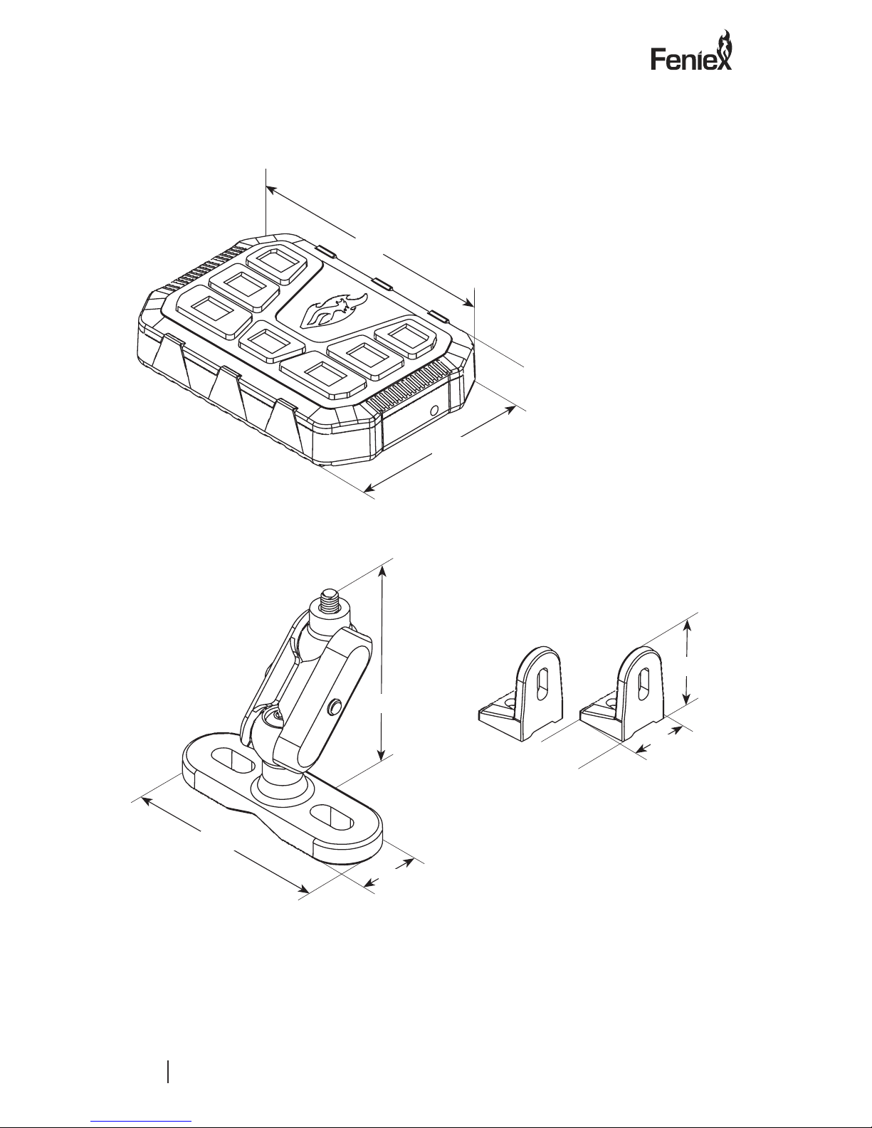
Equipment Dimensions
Mini 4200
3.94in.
0.75in.
2.76in.
0.84in.
0.69in.
2.64in.
2.36in.
1in.
0.63in.
Option 1: Swivel Bracket Option 2: L-Brackets

V2.0
TM
FENIEX. 2016 INSTRUCTION MANUAL
WEB. www.feniex.com
5
Features & specications
System Specication:
Operating Voltage: 12V DC
Max Power Output: 20A
Standby Power 10mA
Number of Outputs: 6
Output Power Rating: 3.5A
Feature 1: Water Proof IP-67
Feature 2: Back-lit LED Panel
Feature 3: 6 Built-in solid state relays
Feature 4: Programmable on/o or momentary
Option 1 Mounting: Swivel Bracket
Option 2 Mounting: Surface Bracket
Button 1 Wig-Wag
Button 2 Wig-Wag
Button 1
Button 3
Button 5
On/O Button
Button 2
Button 4
Button 6

V2.0
TM
FENIEX. 2016 INSTRUCTION MANUAL
WEB. www.feniex.com
6
Wiring Diagram
Wiring Diagram
Blue wire= Activated by switch 3
Yellow wire= Activated by switch 4
Brown wire= Activated by switch 5
Grey wire= Activated by switch 6
White wire= Activated by switch 2
Green wire= Activated by switch 1
Black wire= Ground 12V (-)
Red wire= On: 12V (+)
Programming Instructions:
1.) Setting button as momentary:
• Press the “On/O” button to turn
the system o.
• Press and hold the desired
button you wish to program as
momentary.
• Continue holding the selected
button while holding down the
“On” button for 3 seconds. A beep
will sound when programmed.
• The button is now set as a
momentary button. To reverse the
function, repeat the steps above.
2.) Setting wig-wag functionality:
• Press the “On/O” button to turn
the system o.
• Press and hold buttons 1 and 2
simultaneously.
• Continue holding buttons 1 and
2 while holding down the “On”
button for 3 seconds. A beep will
sound when programmed.
• You have now enabled button 1 as
the “On/O” for wig-wag and the
button 2 as the pattern select.
• To reverse the functionality, repeat
the steps above.
1
3
5
2
4
6

V2.0
TM
FENIEX. 2016 INSTRUCTION MANUAL
WEB. www.feniex.com
7
Mounting installation
1.) Secure the Swivel Ball to the base of the
controller using the #10 screw.
2.) Attach the swivel ball to the swivel
bracket base using the #10 screw.
3.) Using the #10 screw, secure the two
clamps loosely together.
4.) Place the clamps and screw around the
2 swivel balls. Tighten the clamp screw,
thereby attaching the swivel bracket base
to the mini controller.
5.) Secure the Swivel Bracket to the rear of
the controller (as shown in the diagram).
Option 1 Mounting: Swivel Bracket
6.) Place the unit against the intended
mounting surface.
7.) Mark the areas where the mounting
holes will be drilled. If the mounting surface
is part of the vehicle, make sure no vital
components could be damaged by the
drilling process.
8.) Drill two mounting holes on the
mounting surface, making sure no vital
components of the surface are damaged.
9.) Using customer provided screws,
secure the Mini 4200 to the mounting
surface.
V2.0
TM
FENIEX. 2016 INSTRUCTION MANUAL
WEB. www.feniex.com
8
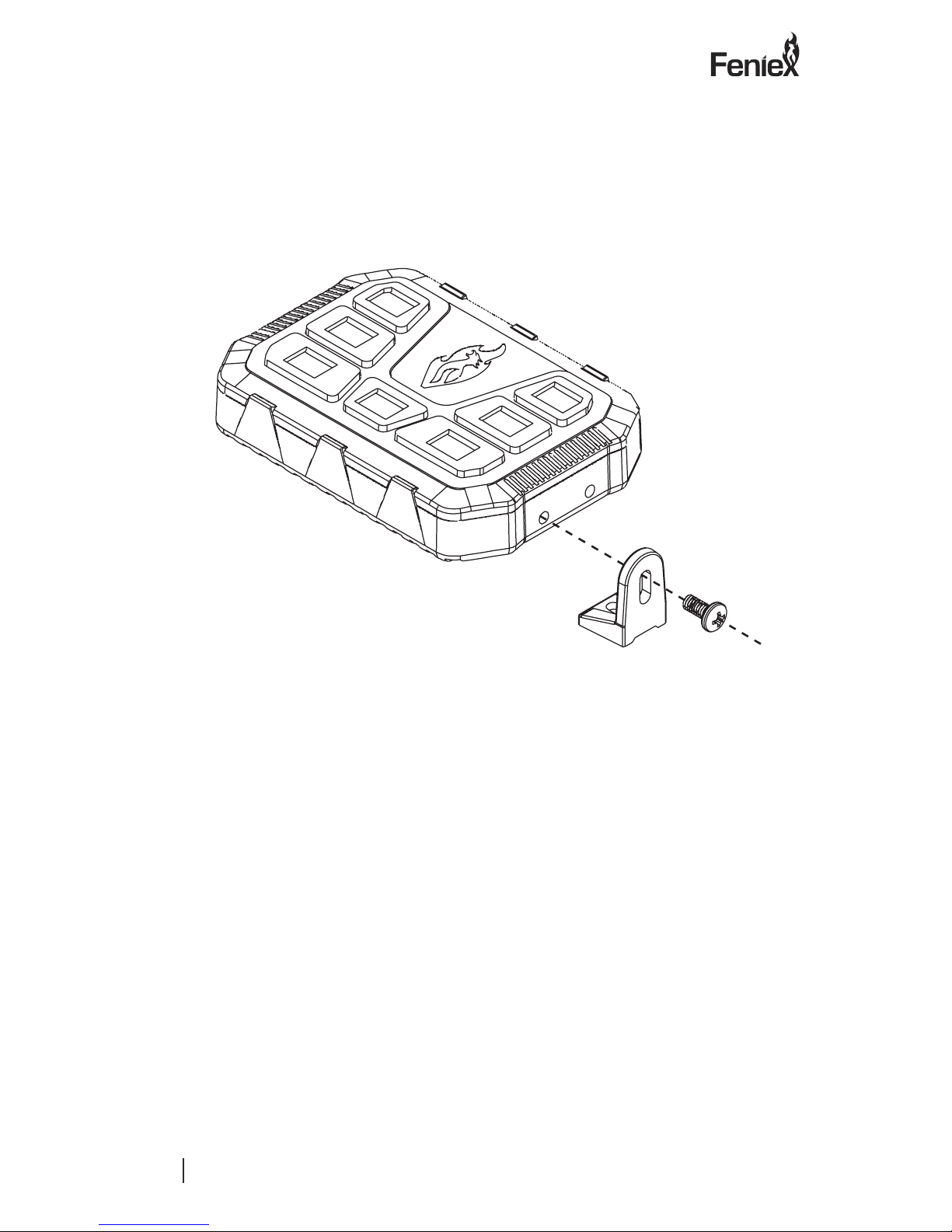
1.) Utilizing the provided screws, secure the
L-Bracket to the side of the controller using
a Phillips head screwdriver.
2.) Repeat Step 1 on the opposite side
of the controller, so both sides have the
L-Bracket securely connected.
3.) Place the unit against the intended
mounting surface.
4.) Mark the areas where the mounting
holes will be drilled. If the mounting
surface is part of the vehicle, make sure
no vital components could be damaged by
the drilling process.
5.) Drill two mounting holes on the
mounting surface, making sure no vital
components of the surface are damaged.
6.) Using customer provided screws,
secure the Mini 4200 to the mounting
surface.
Option 2 Mounting: L-Bracket
Mounting installation
This manual suits for next models
1
Table of contents
Other Feniex Controllers manuals


Popular Controllers manuals by other brands

Digiplex
Digiplex DGP-848 Programming guide

YASKAWA
YASKAWA SGM series user manual

Sinope
Sinope Calypso RM3500ZB installation guide

Isimet
Isimet DLA Series Style 2 Installation, Operations, Start-up and Maintenance Instructions

LSIS
LSIS sv-ip5a user manual

Rockwell Automation
Rockwell Automation 1769-L31 installation instructions


