TECHNICAL FEATURES
The MDS Digitiser is an auxiliary devi e that allows you to onfigure a SKYLINE panel to be integrated in the MDS
DIGITAL installations or ombinations of MDS DIRECT with MDS CITY or VDS.
The onfiguration of the mode in whi h it should fun tion (GENERAL ENTRANCE or INTERIOR BLOCK), is done
via a simple programming after the system installation, keeping in mind the installation's hara teristi s, and in
whi h no tool or spe ial equipment is required.
The following table spe ifies the limitations of ea h of the possible ombinations:
The main te hni al hara teristi s of the MDS Digitiser are as follows:
* Programming via 2 buttons. With a digital display of 4 digits that help programming. This allows for the
programming of MDS DECODERS, MDS/VDS DECODERS when programming and hanging already programmed
telephone numbers.
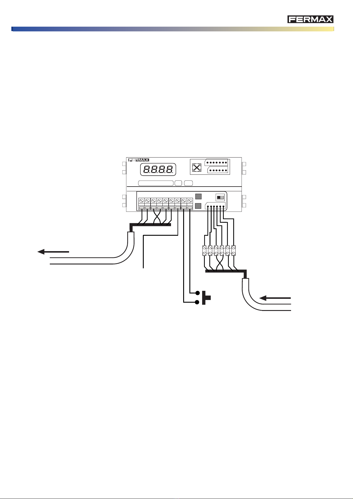
* A tivation time of the lo k release is programmable between 1 and 99 se onds, and indistin tly for the opening
from homes or from the button inside the entran e hall.
GENERAL ENTRANCES INTERIOR BLOCKS LIMITS
Observations:
* You an not onfigure the MDS DIGITAL ombined with the Digitiser onfigured as GENERAL ENTRANCE,
sin e the management of the general entran es is done via the MDS Central Unit via the panel bus.
* "If the installations with MDS Digitiser that are not developments (only one blo k), the limit is 5 a esses and
9999 homes.
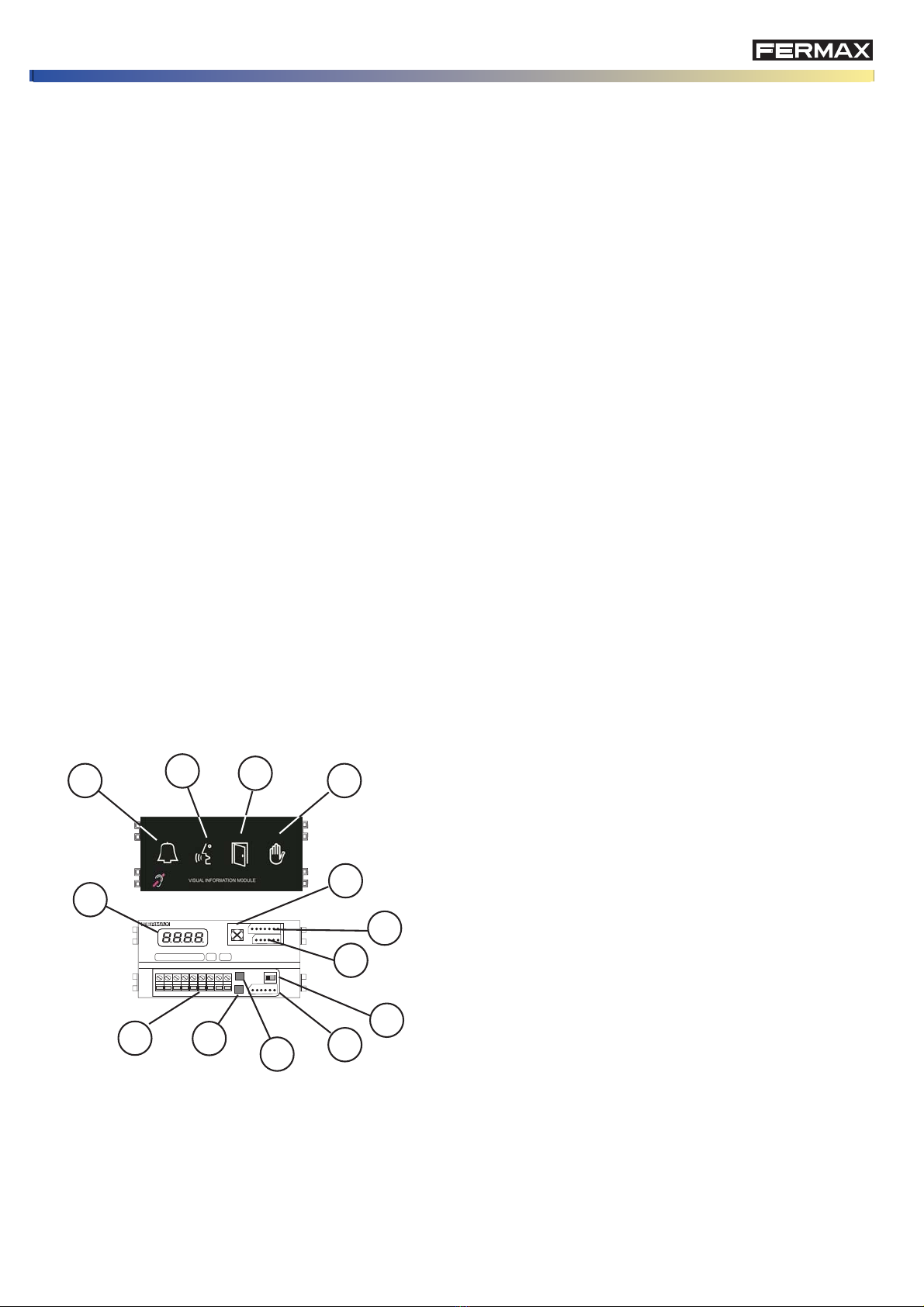
DESCRIPTION OF THE MDS DIGITISER REF. 7460
MDS DIGITAL
- 32 a esses to the General Entran e and/or DIGITAL
Guard Units.
- 99 interior blo ks
- 99 telephones per blo k
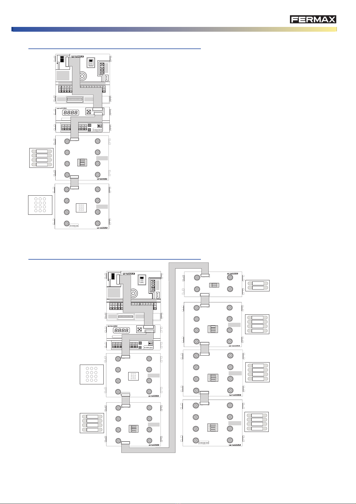
Panel with Digitiser, onfigured
as an INTERIOR BLOCK.
Panel with Digitiser,
onfigured as GENERAL
ENTRANCE
- 5 a esses of MDS DIRECT General Entran e.
- 1 MDS DIRECT Guard unit
- 99 interior blo ks. 9 a esses per blo k.
- 99 telephones per blo k
Digitiser panel, onfigured as
INTERIOR BLOCK
Digitiser panel, onfigured
as a GENERAL
ENTRANCE VDS Panel
- 5 a esses of MDS DIRECT General Entran e.
- 1 MDS DIRECT Guard unit (general)
- 1 VDS guard unit per ea h blo k (lo al)
- 99 interior blo ks. 2 a esses per blo k
- 199 telephones per blo k (installations up to 9
blo ks).
- 99 telephones per blo k (installations from 10 to
99 blo ks)
- installations up to 9999 individual homes