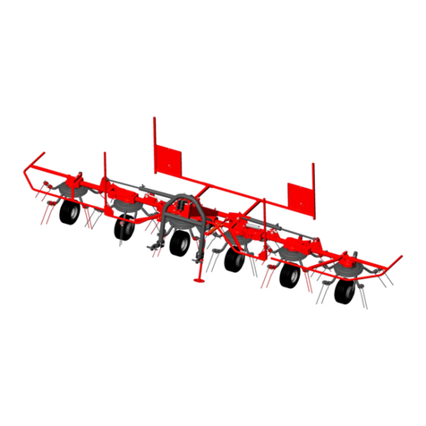
FERPINTA HGR User manual

INTRODUCTION
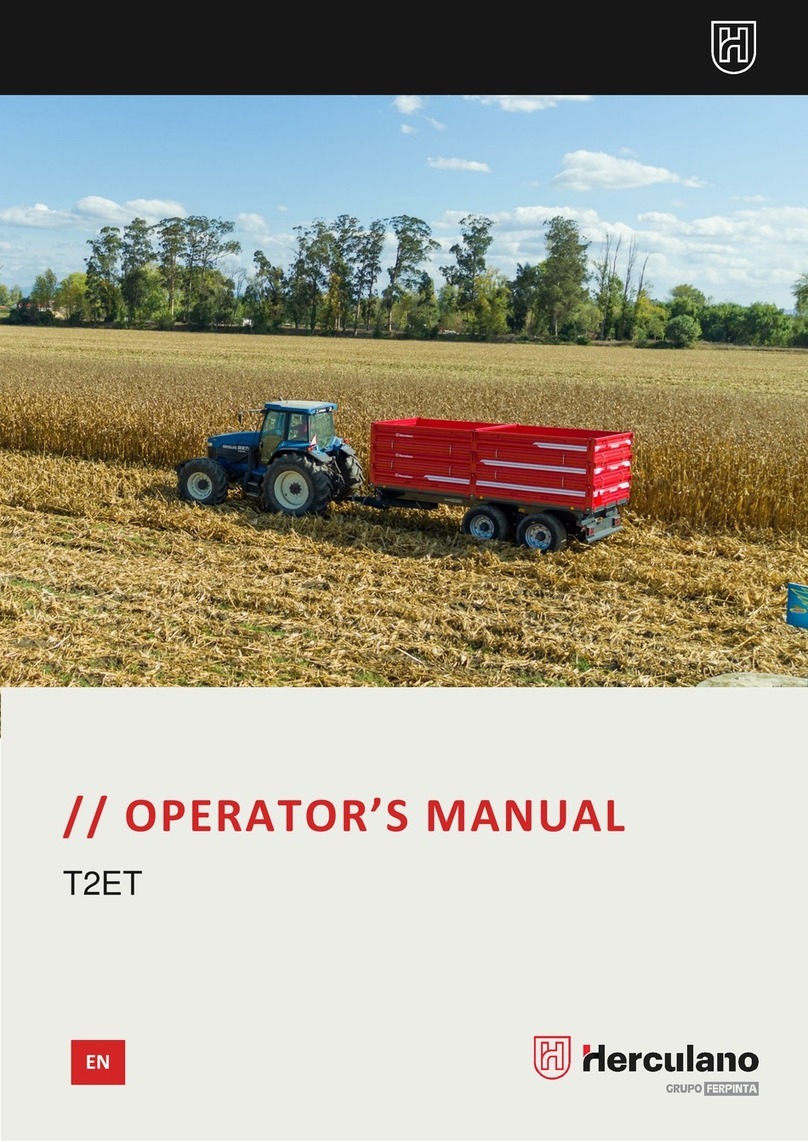
// OPERATOR’S MANUAL
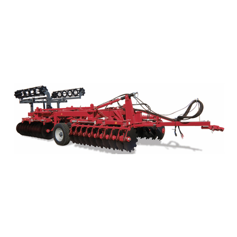
DISC ARROWS •HGR | HGR - H
EN

INTRODUCTION

ÍNDEX
INTRODUCTION__________________________________________
DECLARAÇÃO DE CONFORMIDADE_______________________
SIMBOLOGY_____________________________________________
WARNING LABELS________________________________________
WARNING LABELS POSITION______________________________
TECHNICAL SPECIFICATIONS _____________________________
GENERAL SAFETY RULES __________________________________
TRACTOS’S PREPARATION ________________________________
3 POINT LINLAGE (TUZ) __________________________
DISC HARROW SET’S STABILITY ___________________
COUPLING TO TRACTOR_________________________
STARTING WORK ________________________________________
UPPER ATTACHMENT POINT______________________
DEPTH ADJUSTMENT_____________________________
DISCS SECTIONS________________________________
SIDE SCREENS__________________________________
SCRAPER_______________________________________
OPTIONALS_____________________________________________
LIGHTNING SYSTEM CONNECTION________________________
PREPARE THE MACHINE FOR WORK________________________
UNFOLDING THE MACHINE ______________________
INSTRUCTIONS FOR USE__________________________
TRANSPORTATION ON PUBLIC ROADS____________
MAINTENANCE AND SERVICE_____________________________
TIMETABLE-MAINTENANCE AND SERVICE __________________
MALFUNTIONS OR PROBLEMS / POSSIBLE SOLUTION________
PARTS REPLACEMENT____________________________________
2
3
3
4
5
8
9
11
11
11
12
14
14
14
15
16
18
19
20
21
21
22
23
25
26
29
30
PROLONGED IMMOBLIZATION____________________
WARRANTY CONDITIONS_________________________
HOW TO ORDER PARTS ___________________________
32
33
34

OPERATOR’S MANUAL: DISC ARROWS HGR | HGR - H
2
INTRODUCTION
Dear Customer,
Congratulations on your choice, as you have just purchased equipment built with high technology and
strict quality standards.
All our efforts are put into research, innovation, development and improvement of this product, so that you
can take advantage of the quality, performance, and work in safety.
This manual was created to help you and to advise about safety, maintenance and how to use the
equipment. Thereby, you will be able to use it with confidence to ensure a good performance. Please start
by reading it carefully to become familiar with all the equipment and the most important aspects of safety,
its usage as well as other useful information.
Anyone operating, maintaining, or transporting this equipment must read and thoroughly understand the
instructions outlined in this manual before starting to work.
Please take note of all issues related to safety and instructions included in this manual, complying with them
in order to guarantee your safety and others safety.
Please keep the manual in an accessible and safe place, so that you can refer to it whenever necessary.
It is essential that this equipment is inspected periodically, that it is maintained and fitted with suitable spare
parts.
HERCULANO will provide you with any necessary support, solving problems or clarifying questions that you
may have when using the equipment.
HERCULANO –ALFAIAS AGRÍCOLAS S.A.
3720-051 Oliveira de Azeméis
PORTUGAL

OPERATOR’S MANUAL: DISC ARROWS HGR | HGR - H
3
SIMBOLOGY
DANGER!
Failure to comply with this signal may cause damage
to the equipment and cause serious injuries to people,
endangering your own life.
•All "Danger" instructions must be followed and
respected!
CAUTION!
The special caution signals go next this symbol!
•Please take the necessary precautions and follow
the recommended operating instructions to avoid
problems or accidents.
WARNING!
If you do not respect this signal, you will be subject to
severe injuries and possible damage to the
equipment.
•All "Warning" instructions must be followed and
respected!
MAINTENANCE!
Iconography used for Maintenance and/ or Cleaning!
•Carefully carry out the recommended
maintenance and cleaning procedures in order to
extend the equipment's service life and keeping
the safety conditions.
INFORMATION
Additional useful information goes next these symbols!
•Please read all the points with additional
information carefully since they are useful to
become familiar with your equipment.
“EC” DECLARATION OF CONFORMITY
SAFETY ALERTS
This equipment complies with the requirements of the European Parliament and
Council Directive, 2006/42/EC, of 17 May 2006, transposed into Portuguese law
by Decree-Law No. 103/2008 of 24 June 2008.
The EC Declaration of Conformity is attached to the Trailer User Manual.
This Operator’s manual includes the following symbols:
LUBRICATION!
The Lubrication and Oil Level Replacement
Instructions go next to this symbol!
•Please pay attention to the lubrication points and
periodicity, or the replacement of grease or oil
level. Failure to follow this instruction may
jeopardize the proper performance of the
equipment.


OPERATOR’S MANUAL: DISC ARROWS HGR | HGR - H
4
SAFETY
PERSONAL PROTECTIVE EQUIPMENT
It is very important that the operator wears personal
protective equipment daily to minimize the risks of
an accident.
The instructions in this manual are essential, please
always use PPE's - Personal Protective Equipment
PLEASE WEAR –PROTECTION FOOTWEAR
PLEASE WEAR –PROTECTION GLOVES
PLEASE WEAR–PROTECTION HELMET
PLEASE WEAR –PROTECTION VEST/ CLOTHING
0
READ THE OPERATOR’S USER MANUAL!
Before first usage familiarize yourself with the
instruction manual and safety regulations it
provides.
EW00060
STOP THE ENGINE BEFORE ANY MAINTNANCE
SERVICE!
Turn the engine off and take the key out of ignition
before starting maintenance or service!
EW00061
RISK OF CRUSHING OF THE LIMBS BY WORKING
ELEMENTS OF THE MACHINE OR CUTTING BY SHARP
EDGES!
Keep the distance from the machine! Take special
precautions when replacing sharp elements!
EW00063
RISK OF CRUSHING OF THE BODY WITHIN THE THREE-
POINT LINKAGE OPERATING AREA!
People are not allowed between the harrow and
the tractor when mounting the machine and using
the hydraulic draw- bar!
EW00068
DANGER OF A PALM OR FINGER SQUEEZE BY
MOVING PARTS OF THE MACHINE!
Do not reach the area of moving elements (working
depth regulating actuators, side screens regulation,
outermost discs assembling) during operation or
when the tractor`s engine is on, or when the
hydraulic installation is working!!
EW00062
DANGER OF WHOLE-BODY SQUEEZE WHEN THE
MACHINE SWINGS DURING TURNING!
Do not stay around machine`s range during work or
transportation! Keep safe distance when reversing!
EW00067
MARKS PLACES FOR LIFTING SLING FIXING!
Marks spots suggested for machine`s safe loading
and unloading from the means of transport,
including ensuring its stability when hanging on
ropes, belts, or chains. Always take the lifted
machine`s weight into consideration EW00066
RISK DUE TO UNEXPECTED MOVEMENT OF THE
MACHINE!
This risk can result in serious bodily injuries, potentially
fatal injuries.
Before the machine is detached from the tractor
protect transport wheels with a wedge!
RISK OF CRUSHING OF THE WHOLE BODY OR ITS PART
DUE TO FALLING OF AN UNPROTECTED SUB-ASSEMBLY!
Failure to use a support foot may result in major
injuries. Before the machine is detached, protect the
drawbar against falling by means of a support foot!

OPERATOR’S MANUAL: DISC ARROWS HGR | HGR - H
5
SAFETY
WARNING LABELS POSITION
•PLEASE KEEP THE LABELS LEGIBLE AND IN GOOD CONDITION.
•IF THEY DETERIORATE OR ARE LOST, REPLACE THEM WITH NEW ONES.
(PLEASE ASK THEM FROM YOUR AGENT, OR CONTACT THE MANUFACTURER DIRECTLY)
EW00060
EW00061
EW00068
EW00063
EW00067
EW00066
EW00062
HGR 15 | HGR 17 | HGR 20

OPERATOR’S MANUAL: DISC ARROWS HGR | HGR - H
6
SAFETY
WARNING LABELS POSITION
HGR 25| HGR 27 | HGR 30 | HGR 40
•PLEASE KEEP THE LABELS LEGIBLE AND IN GOOD CONDITION.
•IF THEY DETERIORATE OR ARE LOST, REPLACE THEM WITH NEW ONES.
(PLEASE ASK THEM FROM YOUR AGENT, OR CONTACT THE MANUFACTURER DIRECTLY)
EW00066
EW00062
EW00066
EW00067
EW00068
EW00067
EW00063
EW00061
EW00060

OPERATOR’S MANUAL: DISC ARROWS HGR | HGR - H
7
SAFETY
WARNING LABELS POSITION
EW00060
EW00061
EW00063
EW00068
EW00067
EW00063
EW00062
EW00063
EW00062
EW00062
EW000
HGR 40 H| HGR 50 H | HGR 60 H
•PLEASE KEEP THE LABELS LEGIBLE AND IN GOOD CONDITION.
•IF THEY DETERIORATE OR ARE LOST, REPLACE THEM WITH NEW ONES.
(PLEASE ASK THEM FROM YOUR AGENT, OR CONTACT THE MANUFACTURER DIRECTLY)

OPERATOR’S MANUAL: DISC ARROWS HGR | HGR - H
8
TECHNICAL SPECIFICATIONS
HGR 40 H
HGR 50 H
HGR 60 H
CHARACTERISTICS
WORKING WIDTH (M)
4,0
5,0
6,0
INDICATIVE EMPTY
WEIGHT (KG)
2250
2600
3100
DISCS DIAMETER (“/MM)
22/560
22/560
22/560
DISCS THICKNESS (MM)
6
6
6
NUMBER OF DISCKS
32
40
48
WORKING DEPTH (CM)
14
14
14
RECOMMENDED POWER
(CV)
120-150
140-180
160-200
HGR 15
HGR 17
HGR 20
HGR 25
HGR 27
HGR 30
HGR 40
CHARACTERISTICS
WORKING WIDTH
(M)
1,5
1,7
2,0
2,5
2,7
3,0
4.0
INDICATIVE EMPTY
WEIGHT (KG)
700
780
825
1100
1180
1320
1750
DISCS DIAMETER
(“/MM)
22/560
22/560
22/560
22/560
22/560
22/560
22/560
DISCS THICKNESS
(MM)
6
6
6
6
6
6
6
NUMBER OF
DISCKS
12
14
16
20
22
24
22
WORKING DEPTH
(CM)
14
14
14
14
14
14
14
RECOMMENDED
POWER (CV)
50
60
70
85-115
90-120
100-130
11-150
The Disc Harrow is designed for cultivation of the soil after ploughing and before sowing. The Disc Harrow may
also be used on stubbles on condition that crop residue is crumbled and the stubble is short. The main working
element is a set of disks used for cutting the soil and mixing it intensively afterwards.
The Disc Harrow is designer for cultivation of slightly rocky light and medium soils providing the humidity proper
for agricultural processes, on flat or slightly corrugated terrain. (Maximum slope 8,50).

OPERATOR’S MANUAL: DISC ARROWS HGR | HGR - H
9
GENERAL SAFETY RULES
The below-mentioned safety regulations refer to the disk
harrow mounted on the tractor. Notwithstanding, always
observe general occupational health and safety rules
and road traffic regulations.
•In addition to the recommendations included in this
instruction manual, follow general occupational health and
safety rules as well.
•Observe the warning symbols placed on the machine. Their
observance is for your own safety!
•Stay of any personnel on the machine during work and
transport is forbidden. Before operation, make sure that
nearby the machine there are no bystanders. Pay special
attention to children.
•Lever for the tractor's hydraulic sections should be operated
only from the driver’s seat.
•When the machine is coupled with the tractor, raised or
lowered on the tractor’s hydraulic lift and on the headlands,
check whether there are no bystanders, children in
particular, nearby the the tractor + disk harrow assembly.
•It is forbidden to approach the disk harrow while it is being
lifted and lowered.
•Do not stand between the tractor and the harrow while the
engine is working.
•It is forbidden to reverse the tractor and make turns with the
harrow lowered to the working position.
•While making turns, take the far protruding elements into
account, do not use the brakes independent of the tractor.
•Connect the machine to the tractor as described herein.
•The machine can be connected only to tractors of
adequate power and equipped with category 3 rear three-
point linkage (in accordance with PN-ISO 730-1:1996). Also
remember to choose the tractor's class properly to ensure
its manoeuvrability.
•To maintain proper tractor's manoeuvrability, the machine
should be connected to the tractor equipped with a set of
front axle ballast weights. Pressure of the tractor's front axle
with the mounted harrow must be at least 20% of the
tractor's weight
•Use special, dedicated pins and cotter pins to secure
connections between the machine and the tractor. It is
forbidden to use the substitute means, such as bolts, rods,
wires etc., as these can be sheared or fall out during work or
transport, and thus cause an accident or damage to the
machine. Diameter of the pins must be compliant with the
machine's three-point linkage category.
•It is forbidden to leave the tractor with the machine
mounted on slopes or other sloping areas without protecting
it against uncontrolled rolling. Take special care while
working on the slopes.
•Never leave the tractor with the engine operating. Before
leaving the driver’s seat, lower the machine, turn the
tractor's engine off, remove the ignition key, and engage
the hand brake.
•Because of natural materials wearing out, flexible hydraulic
wires should be replaced every four years. Date of
manufacture (year and number of the week) is placed on
the hydraulic wires.
•Speed must be adjusted to the road conditions.
•When transporting the machine drive your tractor as near
the right side of the road as possible.
•Exercise particular care when driving on public roads,
observe the relevant road traffic rules and regulations. For
the time of transport on the public roads, install the following
on the disk harrow: warning signs painted in white and red
stripes, with lamps: front –white position, rear –red position
and red round reflective (warning signs can be ordered at
the machine's manufacturer on additional charge or
purchased at a point of sale of agricultural machinery) and
a warning triangle for slow moving vehicles.
GENERAL SAFETY RULES

OPERATOR’S MANUAL: DISC ARROWS HGR | HGR - H
10
GENERAL SAFETY RULES
•During transport and work it is forbidden to stand on the
harrow or load it with additional ballast weights.
•During breaks in operation, the harrow should be stored on
a firm and level surface, with all working units lowered in a
place that is inaccessible to unauthorised personnel and
animals.
•Pay particular attention when dismantling and use drawings
provided in the spare parts catalogue.
•When loading, the lifting devices (e.g. forklift truck,
overhead crane) can be operated only by the personnel
with proper qualifications. Elements of the frame (marked on
the machine) should be used as fixing points.
BE CAREFUL! PREVENT ACCIDENTS!
BEFORE START WORKING
•The machine can be used only by adults who hold
adequate qualifications to drive tractors, are familiar with
instruction manuals of both the machine mounted, and the
tractor.
•Antes de começar, verifique se a condição da grade de
disco e do trator garante a segurança rodoviária e do
trabalho.
•The tractor cooperating with the harrow must be equipped
with ballast weights of the front axle. Balance of the tractor
with the machine mounted its manoeuvrability and braking
capacity must be kept. Observe the maximum permissible
load per axle and transport dimensions.
•Exercise particular caution when the machine is being
connected to and disconnected from the tractor. Turn the
tractor's engine off, remove the ignition key, and engage
the hand brake.
•When connecting hoses to tractor's hydraulic system make
sure the hydraulic system is depressurized. Check position of
control levers for the tractor's hydraulic system.
•Appliances controlled by the hydraulic sections can be
activated only when there are no personnel within the
operation area of the machine. There are crushing and
cutting places on the parts activated with the use of the
other force than their own (e.g. hydraulic system).
•Check air pressure in tractor's tyres.
•Balance of the tractor with the machine mounted its
manoeuvrability and braking capacity must be maintained.
Observe the maximum permissible load per axle and
transport dimensions. Balance of the tractor with the
machine mounted its manoeuvrability and braking
capacity must be maintained. Observe the maximum
permissible load per axle and transport dimensions.
•If working units are clogged during operation, clean the
machine by lifting / lowering it few times on the tractor's
linkage.

OPERATOR’S MANUAL: DISC ARROWS HGR | HGR - H
11
PREPARATION OF THE TRACTOR
- Tractor’s overall weight (Kg).
- Front axle load of unloaded tractor (Kg).
- Rear axle load of unloaded tractor (Kg).
- Weight of front ballast weights (Kg).
- Weight of the machine mounted at rear (Kg).
- Distance between centre of gravity of front ballast
weights and centre of the front axle (m).
- Distance between tractor axles (m).
- Distance between the centre of rear axle and
centre of back suspension system couplings (m).
- Distance between the centre of ball joint of rear
suspension system and the centre of gravity of the
mounted machine (m).
The tractor must be equipped with front weights
to ensure the optimum driving properties, proper
mass distribution and equal working depth.
The calculation procedure of the counterweight
mass for the mounted machine as the ballast
weights mounted in front of the tractor are the
following:
−Calculating the increase of the tractor`s rear
axle`s weighting:
11
222222222
3-POINT LINKAGE (TUZ)
Construction of the suspension system assumes that
the tractor and the machine are meant to work
together as set. Functionality of the set is influenced
by the way the upper and lower links on
hangers are regulated.
To make optimal regulation of the BT harrow easier,
in case the tractor has three linking points, the upper
link should be linked to the highest point.
Lower links should be regulated to be set on the
same height
Regulation of the hangers must allow lifting the
machine to the proper height, so that it could be
transported safely.
Regardless of whether the lower links have the
chains attached or not,
the telescopic stretcher bar or other stabilization
system used should be regulated in a way enabling
the BT harrow mounted to the tractor to move
slightly from side to side, without swaying too much
during transportation.
FRONT AXLE LOAD

OPERATOR’S MANUAL: DISC ARROWS HGR | HGR - H
12
PREPARATION OF THE TRACTOR
To verify the total stability so that the minimum weight of front weights can be calculated, what leads to
making sure that the front axle load is at least 20% of the mass of the tractor alone, the formula presented
below can be used:
−Calculating the real load of front axle formula:
−Calculating real total mass formula:
−Calculating real rear axle load formula:
MOUNTING THE HARROW ON TRACTOR
HGR 15 | HGR 17 | HGR 20 | HGR 25| HGR 27 | HGR 30 | HGR 40
Note: For a correct and safe assembly of the harrow,
the tractor must be on firm and level ground.
Proceed as follows:
•Switching the hydraulic system to standing position.
•Putting the ball couplings on harrow catch ball (put
the bolts attached to the harrow through the ball
couplings of tractor`s lower links and secure them
with pins).
•Backing the tractor to the distance enabling linking
the coupling bolts of the harrow to the lower links of
the tractor, as well as connecting the upper link to
the harrow`s hanger
•Connecting the tractor`s upper link and securing its
bolt.
•Regulating tractor`s lower links stabilizators.
•Connecting harrow`s hydraulic wires to the tractor`s
external hydraulic system (if applicable).
•Checking lifting and lowering the harrow, working
section`s folding and unfolding, rear shaft positioning
regulation that are steered hydraulically, (if
applicable).
•Connecting the lighting installation wires (if provided)
by putting the seven-polar plug into the tractor`s
electrical installation slot and check the machine`s
lighting.

OPERATOR’S MANUAL: DISC ARROWS HGR | HGR - H
13
PREPARATION OF THE TRACTOR
MOUNTING THE HARROW ON TRACTOR
HGR 40H | HGR 50H | HGR 60H
Note: For a correct and safe assembly of the harrow,
the tractor must be on firm and level ground. Proceed
as follows:
•Switch the tractor's hydraulic system into position
adjustment;
•Reverse the tractor for a distance enabling
connection of tractor lower links (DC) to latch bar (B)
on the harrow.
•mount ball-and-socket joints of the tractor's lower
links onto latches on the harrow (pass pins provided
with the harrow through ball-and-socket joints and
secure with cotters).
•Adjust the anti-roll bars of the tractor's lower links.
•Connect hydraulic hoses (P) of the harrow to
sockets of external hydraulic sections on the tractor
(H)
•Check lifting and lowering of the whole harrow,
folding of working sections and function of
hydraulically controlled rear roller position
adjustments.
•Connect cable of lighting system of the harrow (if
provided) by plugging the seven-pole plug to the
socket of the tractor's wiring system and check for
proper function of the mounted machine's lighting
system.
BE CAREFUL! PREVENT ACCIDENTS!

OPERATOR’S MANUAL: DISC ARROWS HGR | HGR - H
14
STARTING WORK
UPPER SUSPENTION POINTS
The machine can be connected with the tractor`s
upper link by the permanent slots (OS) or movable
slots (OP) that allow the harrow to lift up slightly when
stumbling upon large disturbing items during working
on rocky fields.
Using movable slots can help eliminating unwanted
machine`s vibrations and swaying.
Movable slots are also recommended for mounting
wide (4m) disk harrows.
When the upper link is connected to the movable slot
of the hanger, the link must be untightened so that
the bolt is unloaded when the harrow is lowered
down.
Note: Movable slots are available on all machines
except HGR 15, HGR 17 and HGR 20 which have 3
slots (OS).
When regulating the tractor`s couplers and changing the geometry of
harrow`s fastening stay cautious! There is a risk of body squeeze!
There is a risk of body squeeze or body parts being cut off by unwanted
and accidental machine and tractor disconnecting! Make sure that no
outsiders are present in the machine`s area during its regulation.
DEPTH REGULATION
Correctly mounted, levelled and adjusted harrow
during cultivation should move evenly behind the
tractor and maintain such position so that the area is
cultivated onto the same depth.
To keep uniform working depth of the harrow, level
the harrow:
•In transverse direction by shortening or
lengthening of the right hanger.
•In lengthwise direction by shortening or
lengthening of the upper connector.
Adjustment of working depth of disks assembly is
done using adjustment located at the coupler
between main frame and rear roller, as the harrow is
lifted by the roller.
To set working depth of the machine by changing
adjustment setting on the frame:
•Lift the machine on the tractor's three-point
linkage lift.
•Remove pins (P) secured with cotters which limit
movements of rear roller arms and the frame of
the machine against each other on the
adjustment gauge (R).

OPERATOR’S MANUAL: DISC ARROWS HGR | HGR - H
15
STARTING WORK
•Turn the actuators (S) on using the tractor`s hydraulic
system (the actuators are placed on each arm- there
are two or three of them, depending on the machine`s
width). Lower or lift the rear shaft towards the main
frame of the disk harrow. If the machine is not
equipped with actuators, it should be lowered or lifted
using TUZ suspension system to change the working
depth settings.
•Secure the shaft`s arms again by putting the pins in the
slots. Make sure that you are using slots placed most
closely to the arms position. Remember! Perform the
described action on both sides of the machine,
making sure that pins are placed equally on both left
and right regulation scales
•Regulate the coupler between the tractor and the disk
harrow so that the harrow is positioned in parallel to the
ground (in working position).
•In case of working resistance exceeding tractor`s
traction output, the working depth should be lowered.
NOTE: It is explicitly important to remember about setting the
regulating pins equally on both sides of the machine.
Disobeying hereby provision will lead to machine`s fast
damage.
If there are problems with pulling the pins out or putting them
back in, the harrow should be unloaded by lifting it up and
letting it fall freely.
DISKS SECTIONS
Both disc sections are mounted to the main frame
using holders allowing for horizontal adjustment of the
discs' working position (three or four holders at each
disc’s section according to working width of the
machine). Thanks to such solution it is also possible to
position the sections against each other in a way
other than factory-set, if the operator finds it is
required by specific soil conditions on a particular lot
(soil type, moisture or amount of harvest residues) to
achieve soil mixture as thorough as possible or to
cover harvest residues.
The horizontal adjustment causes no change in disc
spacing in relation to each other within one section,
or no change in angle of their operation.
ATTENTION! Switching of both disc sections to side
positions (outermost) will cause a slight increase in the
machine's working width and may cause the
machine to leave strips of inaccurate cultivated soil
between rows of discs, operation of which is not
followed by the other section (as a rule each strip of
the soil under cultivation should be “mixed” by two
rows of discs at the same time within a single
passage).

OPERATOR’S MANUAL: DISC ARROWS HGR | HGR - H
16
STARTING WORK
DISK SECTIONS
Para alterar a posição da secção de discos:
•Secure the tractor against rolling and lower the
harrow onto the ground.
•Remove locking screws (R1) on holders of a given
section.
•Loosen nuts of adjustment screws (R2) on holders
of a given section.
•Slightly lift the harrow on the tractor's hydraulic
system and slide the disks section into a desired
position.
•Re-tighten screws R2 and install screws R1.
NOTE: It is recommended that the above procedure related to
change in position of disks section is carried out by a
specialized service.
NOTE: When adjusting disks and whole sections there is a risk
of crushing, cutting, truncation caused by failure to follow
safety regulations!
Never remove adjustment screws as this may cause falling of
the whole machine sub-assembly and thus result in crushing of
the operator's body or it part, including potentially lethal
injuries!
!
SIDE SCREENS
HGR 15 | HGR 17 | HGR 20
Side screens, located at both sections, are intended
to prevent formation of any unevenness at the edge
of the field under cultivation. Properly set screens
disable pouring of the soil onto the strip near the strip
under cultivation and thus provide protection
against formation of undesired unevenness as
bumps or holes on the line between strips of soil
under cultivation.
Each screen can be adjusted for the distance from
the last one on a given disk section.
To change horizontal position of the screen:
•Remove fastening bolt (S).
•Slide screen holder (U) out of the aggregate
frame to fix it in its optimal position.
•Remount the screen holder (U) using bolt (S).
ATTENTION! The above procedure should be carried
out for both screens, from the left and the right side
of the machine

OPERATOR’S MANUAL: DISC ARROWS HGR | HGR - H
17
STARTING WORK
NOTE: When performing horizontal adjustment of the side
screen remember to secure it against falling and sliding from
the disks section frame after adjustment screws are loosened!
If caution is not exercised there is a risk of crushing a part of
the operator's body!
The screen also has vertical position adjustment as
including soil conditions, working depth and driving
speed, the soil thrown by the last disk before the
screen can be released onto a variable height.
To adjust the height of the side screen, proceed as
follows:
•Unscrew (S1, S2 eS3) bolts and adjust the screen
(E) using the existing holes in the support (U).
•Once this is done, retighten the screws.
ATTENTION: The above procedure should be carried out for
both screens, from the left and the right side of the machine.
SIDE SCREENS
HGR 25| HGR 27 | HGR 30 | HGR 40 | HGR 40H | HGR 50H | HGR 60H
In a similar way here too, it is possible to adjust the
horizontal position and the vertical position of the side
screens.
To change horizontal position of the screen:
•Loosen nuts (N) and screws (S).
•Move holder (RP) of the side screen to a desired
position.
•Tighten screws (S) and nuts (N).
To adjust the screen height:
•Unlock and remove pin (P) and insert it in a
desired hole on the gauge (R)
•Secure the pin (P).
This manual suits for next models
1
Table of contents
Other FERPINTA Farm Equipment manuals
Popular Farm Equipment manuals by other brands

SIP
SIP SPIDER 615 PRO Instruction for work

aivituvin
aivituvin XZ7001 instruction manual

Hardi
Hardi COMMANDER DELTA FORCE Instruction book
paladin
paladin HARLEY POWER BOX RAKE T6 Operator's & parts manual
AGRI EASE
AGRI EASE BE-P3FK Operations & parts manual

AIRTUG
AIRTUG TT-M-EM-3 Assembly & operating instructions
