FERPINTA Herculano HMB User manual

// OPERATOR’S MANUAL
HMB •HMB RG •HGMB
EN


OPERATOR’S MANUAL: HMB •HMB RG •HGMB
REV. 04.2022 3
INDEX
INTRODUCTION__________________________________
GENERAL IDENTIFICATION________________________
SIMBOLOGY_____________________________________
EQUIPMENT IDENTIFICATION______________________
AXLE IDENTIFICATION____________________________
WARNING LABLES________________________________
WARNING LABELS POSITION ______________________
TECHNICAL SPECIFICATIONS______________________
GENERAL SAFETY RULES __________________________
STARTING WORK_________________________________
HYDRAULIC SYSTEMS_____________________________
HYDRAULIC SYSTEMS CONNECTION______
DRAWBAR SUPPORT LEG_________________
DRAWBAR HYDRO-PNEUMATIC
SUSPENSION____________________________
SELF STEERING AXLES SYSTEM ____________
FORCED STEERING AXLES SYSTEM ________
SIMPLE TIPPING HYD. SYSTEM ____________
INDEPENDENT HYDRAULIC SYSTEM________
INDEPENDENT HYDRAULIC SYSTEM WITH
PUMP MOTOR GROUP___________________
REAR AXLE STABILIZATION SYSTEM________
REAR AXLE LOCKING SYSTEM ____________
HYDRAULIC DOOR + LATCHES____________
HYDRAULIC BRAKING SYSTEM____________
4
5
6
7
7
8
10
11
14
16
18
18
18
19
20
21
25
26
28
30
31
32
33
HYDRAULIC BRAKING SYSTEM + WITH 3
POSITION MANUAL VALVE ________________
PNEUMATIC BRAKING SYSTEM______________________
ELETRICAL SYSTEM_________________________________
LIGHTS AND INDICATOR SIGNALS___________________
PARKING BRAKE | EMERGENCY BRAKE _____________
GENERAL PRECAUTIONS ___________________________
SUSPENSIONS_____________________________________
OPTIONALS_______________________________________
TARPAULINS______________________________
OPTIONAL MISCELLANEOUS_______________
DRAWBARS_______________________________
DEVICES TO PREVENT UNAUTHORIZED USE ___________
MAINTENANCE AND SERVICES _____________________
BRAKES –DRUM OVERHEATING____________
BRAKES | JAWS ADJUSTMENT______________
AXLE | WHEEL | SUSPENSION SERVICE______
WHEEL CHANGING _______________________
HUBS AND BEARINGS _____________________
ALB –VALVE ADJUSTMENT_________________
TIMETABLE: MAINTENANCE AND SERVICES___________
MALFUNTIONS | POSSIBLE SOLUTIONS_______________
PROLONGED IMMOBLIZATION | END OF LIFE ________
WARRANTY CONDITIONS___________________________
HOW TO ORDER PARTS?____________________________
33
35
37
38
40
41
42
43
43
44
46
48
49
49
50
51
54
55
56
57
60
65
66
67

OPERATOR’S MANUAL: HMB •HMB RG •HGMB
REV. 04.2022 4
INTRODUCTION
Dear Customer,
Congratulations on your choice, as you have just purchased equipment built with high technology and
strict quality standards.
All our efforts are put into research, innovation, development and improvement of this product, so that
you can take advantage of the quality, performance, and work in safety.
This manual was created to help you and to advise about safety, maintenance and how to use the
equipment. Thereby, you will be able to use it with confidence in order to ensure a good performance.
Please start by reading it carefully in order to become familiar with all the equipment and the most
important aspects of safety, its usage as well as other useful information.
Anyone operating, maintaining, or transporting this equipment must read and thoroughly understand the
instructions outlined in this manual before starting to work.
Please take note of all issues related to safety and instructions included in this manual, complying with
them in order to guarantee your safety and others safety.
Please keep the manual in an accessible and safe place, so that you can refer to it whenever necessary.
It is essential that this equipment is inspected periodically, that it is maintained and fitted with suitable
spare parts.
HERCULANO will provide you with any necessary support, solving problems or clarifying questions that you
may have when using the equipment.
HERCULANO –ALFAIAS AGRÍCOLAS S.A.
3720-051 Oliveira de Azeméis
PORTUGAL

OPERATOR’S MANUAL: HMB •HMB RG •HGMB
REV. 04.2022 5
GENERAL IDENTIFICATION
HMB 8000 HMB 14000 HMB 18000
HMB 10000 ES HMB 14000 RG HMB 18000 RG
HMB 10000 HMB 16000 HMB 24000
HMB 12000 HMB 16000RG HMB 24000 RG
HGMB 10000 HGMB 14000 HGMB 18000
HGMB 12000 HGMB 16000
HMB
HGMB

OPERATOR’S MANUAL: HMB •HMB RG •HGMB
REV. 04.2022 6
SYMBOLOGY
DANGER!
Failure to comply with this signal may cause damage
to the equipment and cause serious injuries to people,
endangering your own life.
•All "Danger" instructions must be followed and
respected!
WARNING!
If you do not respect this signal, you will be subject to
severe injuries and possible damage to the
equipment.
•All "Warning" instructions must be followed
and respected!
•
INFORMATION
Additional useful information goes next these symbols!
•Please read all the points with additional
information carefully since they are useful to
become familiar with your equipment.
•
CAUTION!
The special caution signals go next this symbol!
•Please take the necessary precautions and
follow the recommended operating
instructions to avoid problems or accidents.
EC DECLARATION OF CONFORMITY
This equipment complies with the requirements of the European Parliament and Council Directive,
2006/42/EC, of 17 May 2006, transposed into Portuguese law by Decree-Law No. 103/2008 of 24 June
2008.
The EC Declaration of Conformity is attached to the Trailer User Manual.
SAFETY ALERTS
MAINTENANCE!
Iconography used for Maintenance and/ or Cleaning!
•Carefully carry out the recommended
maintenance and cleaning procedures in
order to extend the equipment's service life
and keeping the safety conditions.
•
LUBRIFICATION!
The Lubrication and Oil Level Replacement
Instructions go next to this symbol!
•Please pay attention to the lubrication points
and periodicity, or the replacement of grease
or oil level. Failure to follow this instruction may
jeopardize the proper performance of the
equipment.
•

OPERATOR’S MANUAL: HMB •HMB RG •HGMB
REV. 04.2022 7
IDENTIFICAÇÃO DO EQUIPAMENTO
ID TAG PLATES
IDENTIFICATION NO.
TX7 * * * * * * * * * * * * * *
The information of the serial number and type of axle is
stamped on the identification plate located at the
following place:
•Improves safety in the event of an accident;
•Minimizes the consequences of rear-end collisions;
•Prevents underride accidents at the rear-end of the
vehicle;
- Maximum load
400x80 AXLES
LABEL
ID1
ID2
ID3
ID4
FAD
L9
40081A
8829
36102819
EB / AMB
FF
400x80V
7848
36103119
EB / AMB
FF
400x80V
6867
36106718
ADR
TG ou
TC
408E
7848
36105319
400x120 AXLES
LABEL
ID1
ID2
ID3
ID4
FAD
M101
40122E
10000
36104417
406x120 AXLES
LABEL
ID1
ID2
ID3
ID4
ADR
VC
412E
11282
36106111
EB/AMB
6J
406x120V
11282
36110811
420x180 AXLES
LABEL
ID1
ID2
ID3
ID4
EB/AMB
8K
420x180V
12753
36110712
ADR
XC
4218E
10791
36106616
ADR
XC
4218E
12753
36106511
EQUIPEMENT IDENTIFICATION
WMI
CODE
Vehicle
ID
Serial
Manufacture
No.
AXLE IDENTIFICATION
AXLE IDENTIFICATION PLATE
(OR)
The plates can be metallic or as stickers. They enclose
important information as they identify the type of axle
and in case it is needed a repair or replacement of parts.
EXAMPLE OF AN (ADR) AXLE IDENTIFICATION STICKER
APROVED –UNDERRUN BAR
The trailer is equipped with homologated bumpers.
- Category
- Homologation No
- Identification
No.
Technically allowable
- Load on the device
- Load on the 1st
axle
- Load on the 2 nd
axle
- Load on the 3 rd
axle

OPERATOR’S MANUAL: HMB •HMB RG •HGMB
REV. 04.2022 8
SAFETY
PLEASE WEAR - PROTECTION HELMET
PLEASE WEAR - PROTECTION VEST / CLOTHING
PLEASE WEAR - PROTECTION GLOVES
PLEASE WEAR - BOOTS / PROTECTION FOOTWEAR
WARNING STICKER LABELS
Warning stickers are part of the User Manual. Please
follow all procedures, keep the stickers legible and
immediately replace any lost or damaged labels.
Danger of crushing! Always attach the
safety prop!
7 AC 016
Danger of crushing! Do not tip over
unstable or sloping ground!
7 AC 017
Danger of crushing!
Box with tipping!
7 AC 015
Danger! Articulated machine!
7 AC 004
Please always read the User Manual.
7 AC 001
Danger of crushing!
Tipping rear door!
Keep away from the door's tipping area while
the tractor is running!!
7 AC 018
7 AC 019
Danger of electric shock / electrocution - overhead
power lines!
Please keep the safety distance.
(if applicable)
7 AC 119
Lubrication point!
7 AC 082
Tire pressure indicator. Inflation pressure
varies depending on the fitted wheel.
7 AC 024
Indication of wheel and torque
tightening periodicity.
7 AC 111
Warning to keep the steering
stopcocks open!! (if applicablel)
7 AC 118
PERSONAL PROTECTIVE EQUIPMENT
It is very important that the operator wears personal
protective equipment on a daily basis in order to
minimize the risks of an accident.
The instructions in this manual are essential, please
always use PPE's - Personal Protective Equipment
Warning to check the stopcocks on
the steering axles! (if applicable)
7 AC 118.1
Maintenance instructions for
Tridem suspension! (if
applicable)
7 AC 123
Elevation points.
7 AC 137.1
7 AC 137.2
7 AC 137.3
7 AC 138.1
7 AC 138.2

OPERATOR’S MANUAL: HMB •HMB RG •HGMB
REV. 04.2022 9
SAFETY
Warning to adjust the manual valve of the hydraulic braking system,
according to the load you want to transport. (if applicable)
7 AC 124.1
Warning to read the Instruction Manual and to ensure the AMB / ADR
ASSEMBLY DIMENSION = 250mm (If applicable)
7 AC 132
Warning to read the Instruction Manual and to ensure the FAD
ASSEMBLY DIMENSION = 200mm (If applicable)
7 AC 133
Matching timetable of the Hydraulic Functions by color.
7 AC 116
3 way braking valve. Min / MED / MAX
(When applicable)
7 AC 124
Warning! Compatibility of
new tires and pressure
regulation.
(When applicable)
7 AC 126.2
•Please keep the labels legible and in good condition.
•If they deteriorate or are lost, replace them with new ones.
(Please ask them from your agent, or contact the manufacturer directly)
Warning to adjust the Rear
Door Latches!
7 AC 125
Warning for the depressurization
valve location!
(if applicable)
7 AC 127
Warning!
Lubrication and Oil
Change Periodicity
Warning to adjust the
electric valve of the braking
system, according to the
load transportation needed.
(If applicable)
7AC 135

OPERATOR’S MANUAL: HMB •HMB RG •HGMB
REV. 04.2022 10
SAFETY
WARNING LABELS POSITION
7 AC 018
7 AC 019
7 AC 127*
ID TAG
PLATE
7 AC 015 (1 each side)
7 AC 123*
7 AC 137.1*
7 AC 137.2*
7 AC 137.3*
7 AC 138.1*
7 AC 138.2*
7 AC 111
7 AC 024
7 AC 118.1*
OPTIONAL
7 AC 082
7 AC 004
7 AC 082
Pneumatic
braking
system
7 AC 118.1*
7 AC 116
(Applied at the other side)
7 AC 118.1*
7 AC 118
7 AC 124*
7 AC 124.1*
REAR
FRONT
7 AC 119
7 AC 001
7 AC 126*
7 AC 116
7 AC 017
7 AC 125*
7 AC 082
7 AC 082
7 AC 004

OPERATOR’S MANUAL: HMB •HMB RG •HGMB
REV. 04.2022 11
TECHNICAL SPECIFICATIONS
HMB
HERCULANO has a variety of Monocoque Trailers available
whose pay load ranges from 8,000 kg to 24,000 kg. All
models are built with tapered body and equipped with a
hydraulic door and latches that guarantee a good tightness
and sealing. These models are prepared for agriculture and
works outside the field.
There is also a wide range of tools and optional equipment
which can be added to the trailer, to increase the
productivity and better suit your type of work.
HGMB
MAIN SPECIFICATIONS
METAL BODY
•TAPERED MONOCOQUE
CHASSIS
•STRUCTURAL TUBE
WHEELS (RANGE)
•435/50 R19.5
•385/65 R22.5
•425/65 R22.5
•550/60-22.5 16PR
•650/55 R26.5
AXLES
•FIXED
•SELF-STEERING
•FORCED STEERING
SUSPENSION
•BOGGIE
•TANDEM
•TRIDEM
BRAKING
•HYDRAULIC
•PNEUMATIC
•MIXED
HYDRAULIC REAR DOOR
HEIGHT ADJUSTABLE DRAWBAR
•WINTH NO SPRING (SEMI-TRAILER)
•WITH SPRING (SEMI-TRAILER)
•ROTARY DRAWBAR (TRAILER)
DRAWBAR
•HYDRAULIC
LIGHTNING
•NORMAL –Filament lamps
•LED
MUDGUARDS
•PLASTIC
ADDITIONAL EXTENSIONS
•STEEL SHEET H = 300mm
•STEEL SHEET H = 500mm
•STEEL SHEET H = 800mm
•STEEL MESH H = 800mm
•STEEL SHEET + MESH H = 800mm

OPERATOR’S MANUAL: HMB •HMB RG •HGMB
REV. 04.2022 12
TECHNICAL SPECIFICATIONS
MONOCOQUE TRAILERS –HMB | HMB RG
DESIGNATION
HMB
8000
HMB
10000
ES
HMB
10000
HMB
12000
HMB
14000
HMB
14000
RG
HMB
16000
HMB
16000
RG
HMB
18000
HMB
18000
RG
HMB
24000
HMB
24000
RG
BODY 1.5m
(Internal Height)
1,5m
1,5m
1,5m
1,5m
1,5m
1,5m
1,5m
1,5m
1,5m
1,5m
1,5m
1,5m
Total Height (mm)
(Standard Wheels)
2700
2815
2740
2770
2790
3060
2830
3060
2900
3060
2900
3060
Fully Tipped Height
(mm)
4942
5475
5484
5850
6300
6300
6800
6800
7100
7100
8380
8375
Maximum Total Length (mm)
5750
6350
6325
6750
7340
7315
7740
7700
8340
8300
9760
9750
Tipping Cylinder
No. of Strokes
4
4
4
4
4
4
5
5
5
5
5
5
Tipping Cylinder Ø (mm)
145
145
145
165
165
165
185
185
185
185
200
200
Tipping Cylinder
Total Length (opened) (mm)
1710
1885
1885
2215
2215
2215
2760
2760
3190
3190
2950
2950
Tipping Cylinder
Pressure
180 Bar
180 Bar
180 Bar
180 Bar
180 Bar
180 Bar
180 Bar
180 Bar
180 Bar
180 Bar
180
Bar
180
Bar
Tipping Cylinder
Oil Volume
13,2 Lt.
14,5 Lt.
14,5 Lt.
23,1 Lt.
23,1 Lt.
23,1 Lt.
34,1 Lt
39,4 Lt
39,4 Lt
39,4 Lt
45,9 Lt
45,9 Lt
Rear Tipping Angle
46º
44º
44º
45º
45º
45º
50º
50º
53º
53º
49º
49º
Axle Frame (mm)
100
100
90
100
100
150
100
150
110
150
130
150
Hub - Brakes (mm)
1 AXLE
400x80
1 AXLE
406x120
2 AXLES
400x80
2 EIXOS
400x80
2 AXLES
400x80
2 AXLES
406x120
2 AXLES
400x80
2 AXLES
406x120
2 AXLES
406x120
2 AXLES
406x120
3 AXLES
400x120
3 AXLES
406x120
No. of Bolts - Axle
8
10
8
8
8
10
10
10
10
10
10
10
The presented values refer only to “STANDARD” models

OPERATOR’S MANUAL: HMB •HMB RG •HGMB
REV. 04.2022 13
TECHNICAL SPECIFICATIONS
MONOCOQUE TRAILERS - HGMB
DESIGNATION
HGMB 10000
HGMB 12000
HGMB 14000
HGMB 16000
HGMB 18000
BODY 1.5m
(Internal Height)
1,5m
1,5m
1,5m
1,5m
1,5m
Total Height (mm)
(Standard Wheels)
2680mm
2680mm
2680mm
2680mm
2800mm
Fully Tipped Height (mm)
5525mm
5805mm
6155mm
6640mm
6895mm
Maximum Total Length (mm)
6580mm
6980mm
7580mm
7980mm
8625mm
Tipping Cylinder
No. of Strokes
4
5
4
5
5
Tipping Cylinder Ø (mm)
140 mm
165 mm
165 mm
185 mm
185 mm
Tipping Cylinder
Total Length (opened) (mm)
1885 mm
2215 mm
2215 mm
2760 mm
2760 mm
Tipping Cylinder
Pressure
180 Bar
180 Bar
180 Bar
180 Bar
180 Bar
Tipping Cylinder
Oil Volume
14,5 Lt.
23,1 Lt.
23,1 Lt.
34,1 Lt.
34,1 Lt.
Rear Tipping Angle
44º
45º
45º
50º
53º
Axle Frame (mm)
100 mm
100 mm
100 mm
100mm
100 mm
Hub - Brakes (mm)
1 FIXED AXLE + 1
ROTATARY AXLE
400x80
1 FIXED AXLE + 1
ROTATARY AXLE
400x80
1 FIXED AXLE + 1
ROTATARY AXLE
400x80
1 FIXED AXLE + 1
ROTATARY AXLE
400x80
2 FIXED AXLES (BOGIE)
+ 1 ROTATARY AXLE
400x80
No. of Bolts - Axle
8
8
8
8
8
The presented values refer only to “STANDARD” models

OPERATOR’S MANUAL: HMB •HMB RG •HGMB
REV. 04.2022 14
GENERAL SAFETY RULES
GENERAL SAFETY RULES
•HMB semi-trailers and HGMB trailers have been
developed for the agricultural market, to work on
and off the field, thanks to their sealed body. They
must not be used for purposes other than those
mentioned, as they may jeopardize your safety and
others' safety.
•Before carrying out any maintenance or repair
operation on the equipment that requires tipping,
make sure that the vehicle is properly stabilized and
on flat ground with wheel chocks on the wheels.
Switch off the engine and properly put the tractor
and trailer's brake on before proceeding with any
operation that may jeopardize your safety.
•Serious fatal errors can occur if precautions are not
taken and safety measures are not respected.
•The damaged components and equipment must
only be replaced, by certified or qualified people for
this purpose.
•Always use the most suitable tools as well as
personal protective equipment at work and during
vehicle maintenance operations and repairs.
•Make sure that all spare parts and components are
compatible with the equipment requirements and
that they do not affect the correct functionality, the
safety of the vehicle, your safety, or others' safety.
•It is always recommended to use original
manufacturer’s spare parts and components to
ensure properly fittings, promote security and that
they do not affect the vehicle’s structural capacity
or safety.
•Make sure that you carry out all inspections and
services on your equipment at specific time ranges.
Equipment Modification:
The chassis frame and structures, wheels, braking system, hydraulic or pneumatic systems and electrical system must not
be modified or reconverted, as they are important safety elements and, if they are altered, may jeopardize the safety of
the equipment.

OPERATOR’S MANUAL: HMB •HMB RG •HGMB
REV. 04.2022 15
GENERAL SAFETY RULES
•Whenever carrying out coupling / decoupling of
the equipment, it is strictly forbidden to stand
between the tractor and trailer unless they are
properly immobilized with the parking brake on
and, if applicable, with chocks on wheels.
•When coupling the semi-trailer to the tractor,
please, stand in one side of the tractor and make
sure that the safety pins / chains are properly
fitted.
•Always wear suitable clothes and shoes, avoiding
the use of loose or baggy clothing.
•Never carry out maintenance work when the
body is tipped, without first placing the safety
prop between the upper and lower chassis.
•Do not allow people to remain or ride in the trailer.
•Always check the pressure and general condition
of the trailer's and tractor's tires prior to each use.
•The equipment’s legal pay load limits must not be
exceeded.
•Always comply with your tractor’s towing
admissible load limits.
•Regularly check the general condition of the
hydraulic and pneumatic hoses if applicable,
replace them if they are damaged or worn.
Replacement hoses must meet the technical
requirements specified by the manufacturer.
•Check oil levels regularly and keep the
lubrication points properly lubricated and check
if they are not dirty.
•Before starting transportation, check if the
braking system is working properly.
•When driving on public roads, comply with the
rules in force. Always check if the lightning
devices fitted to the rear, side and front of the
vehicle, work correctly.
•Depending on the characteristics of the
equipment and the type of product loaded, the
total weight of the vehicle under full load may
exceed the Maximum Allowable Mass regulated
in the country in which it travels. In the case of
traffic on public roads, the user must ensure
compliance with the dimensions and masses
defined in the legislation and highway code
applicable in the country. Herculano will not be
held responsible for any consequences arising
from non-compliance with legal requirements.

OPERATOR’S MANUAL: HMB •HMB RG •HGMB
REV. 04.2022 16
STARTING WORK
TECHNICAL SPECIFICATION: TIRE DIMENSIONS AND PRESSURES /
WHEEL TIGHTNING TORQUE HMB | HGMB
DIMENSION
TYRE / WHEEL
MAX PRESSURE
BOLTS
RECOMMENDED
TORQUE
(N.m)
(BAR)
(Psi)
435 / 50 R19.5
9
130
8 x M20
350 a 380
425 / 65 R22.5
9
130
8 x M20
350 a 380
550 / 60-22.5
16 PR
2,8
41
10 x M22
400 a 420
385 / 65 R22.5
9,5
138
10 x M22
400 a 420
600 / 55 R26.5
4
58
10 x M22
400 a 420
* OTHER TYRES / WHEELS –PLEASE ASK
Before starting work, the user must be aware of all the
equipment and its functions. Getting to know the
systems after starting to work may be too late!
The equipment must always be tested before each
operation and before driving on public roads!
When tipping, please note there is a danger of
crushing, cutting or ejecting! Do not allow people to
remain at the rear or on the sides of the trailer when
tipping.
Do not start driving with a tipped trailer.
Before starting to drive, make sure that the door is
closed, the body is not tipped and ensure that there
are no people in the rear and side areas near the
trailer.
Follow the instructions and always keep in mind all
warnings and safety signs included in the manual
and on your trailer.
BEFORE STARTING WORK
BEFORE STARTING THE OPERATION
1. Make sure that all safety equipment is in good
working and maintenance condition.
2. Make sure to keep the joints / lubrication points
properly lubricated. Check oil levels regularly
and check for any looseness in the suspension or
in the axles, and for damaged bearings.
3. Make sure that the tires are inflated to the proper
pressure and that they are in good general
condition.
4. Check the tightness of the wheels.
5. Connect the trailer electrical plugs to the tractor
and make sure the electrical system works
properly.
6. Ensure the proper functioning of the trailer with
only the accessories / equipment provided.
7. Connect all hydraulic and / or pneumatic
sockets (if applicable) to the tractor.
•Check the hydraulic hoses for wear or
leakage.
•Make sure you connect the hoses correctly.
8. Check the parking brake system as well as the
service brake.

OPERATOR’S MANUAL: HMB •HMB RG •HGMB
REV. 04.2022 17
TRAILER COUPLING TO TRACTOR
When you need to couple / uncouple the trailer to
the tractor, no one should be present in the area
between the two vehicles! This is considered a
danger zone!
NOTE: Before starting the coupling, make sure that
the trailer is on a flat ground and that the parking
brake is properly on. If you have chocks, always
make sure that the trailer wheels are chocked before
starting the following procedures.
TRAILER COUPLING TO TRACTOR
1º Align and move the tractor’s coupler towards the
coupler's device of the trailer’s drawbar;
2º Connect the drawbar’s safety chains to the
tractor;
3º Connect all trailer's hydraulic and pneumatic
hoses (if applicable) to the tractor's hydraulic
sockets.
Note: The tractor must be off;
4º Connect the plugs of the trailer electrical systems
to the tractor’s socket;
5º Operate the drawbar rest hydraulic cylinder in
order to level the coupling device with the
tractor coupler
6º Slowly move the tractor in reverse until it aligns
the tractor's coupler with the coupler's device of
the trailer’s drawbar. When they are properly
aligned, proceed to the coupling;
7º Make sure you have completed the previous
step correctly and retract the hydraulic cylinder
from the drawbar to the operating position;
8º Remove the chocks from the wheels (if fitted)
and proceed to work safely by releasing the
hand brake / parking brake.
! WARNING !
PEOPLE IN THE DANGER ZONE BETWEEN THE
TRACTOR AND THE TRAILER MAY BE CRUSHED OR
RUN OVER!
KEEP OUT ALL PEOPLE FROM THE DANGER ZONE WHEN TO
COUPLING / UNCOUPLING THE TRAILER;
NO ONE IS AUTHORIZED TO REMAIN ALONGSIDE THE
TRAILER'S AXLES / TRACTOR WHEN THEY ARE BEING
COUPLED;
THE TRACTOR'S DRIVER MUST ALWAYS STAY CLEAR OF
VEHICLE WHEEL

OPERATOR’S MANUAL: HMB •HMB RG •HGMB
REV. 04.2022 18
HYDRAULIC SYSTEMS
CONNECTION OF HYDRAULIC SYSTEMS
DRAWBAR SUPORT LEG
Note: For safety reasons, never connect or disconnect the
hydraulic systems with the body tipped! When connecting
or disconnecting the hydraulic systems, make sure that the
edges of the quick-connect valves are not dirty!
The connections of the tractor's hydraulic functions must
not exceed 180 bar. Pressures above this value may
damage the systems.
HYDRAULIC SYSTEMS: HMB | HGMB
•DRAWBAR HYDRAULIC JACK
•DRAWBAR'S HYDRO-PNEUMATIC SUSPENSION (WHEN APPLICABLE)
•SELF-STEERING AXLES' SYSTEM (WHEN APPLICABLE)
•FORCED STEERING AXLES' SYSTEM (WHEN APPLICABLE)
•TIPPING HYDRAULIC SYSTEM (WHEN APPLICABLE)
•INDEPENDENT HYDRAULIC SYSTEM (WHEN APPLICABLE)
•INDEPENDENT HYDRAULIC SYSTEM PUMP MOTOR GROUP
(WHEN APPLICABLE)
•REAR AXLE STABILIZATION SYSTEM (WHEN APPLICABLE)
•REAR AXLE SUSPENSION LOCKING SYSTEM (WHEN APPLICABLE)
•HYDRAULIC REAR DOOR + DOOR LATCHES
•HYDRAULIC BRAKING SYSTEM (WHEN APPLICABLE)
•
1º Properly put the tractor’s brake on and then
switch it off;
2º Close the safety cock on one of the hydraulic
hoses on the drawbar.
3º Connect the two appropriate hoses to the
tractor.
4º After connecting the hoses to the tractor, open
the safety stopcock.
5º Before turning on the tractor, make sure you
complete the connection of all the other
systems.
Never disconnect the hoses from the tractor without first
closing the safety stopcock.
If you experience difficulties connecting the hose that
contains the stopcock, first make sure that it is closed
and try to activate the quick attachment valve, in order
to depressurize the short link present between the two
elements. In doing so, it should be easy to make the
coupling.
1º Make sure that the box is not tipped and that the
hydraulic door is closed;
2º Move the tractor closer and lower the tractor’s linkage
in order to have access to the hydraulic sockets area;
3º Switch off the tractor’s engine;
4º With the trailer properly immobilized and with the chocks
on the wheels (if applicable), connect the hydraulic
hoses of all systems to the corresponding hydraulic
sockets of the tractor;
5º If your trailer is equipped with an Independent Hydraulic
System, connect the trailer's hydraulic pump to the
tractor's power take-off.
6º Connect the electrical plug of the Lightning System and
the function control to the tractor;
7º Switch on the tractor's engine and reposition the linkage
in an elevated position to prevent collision with the
drawbar during transport.
8º
T
P
OPERATOR’S MANUAL: HMB •HMB RG •HGMB
REV. 04.2022 19
HYDRAULIC SYSTEMS
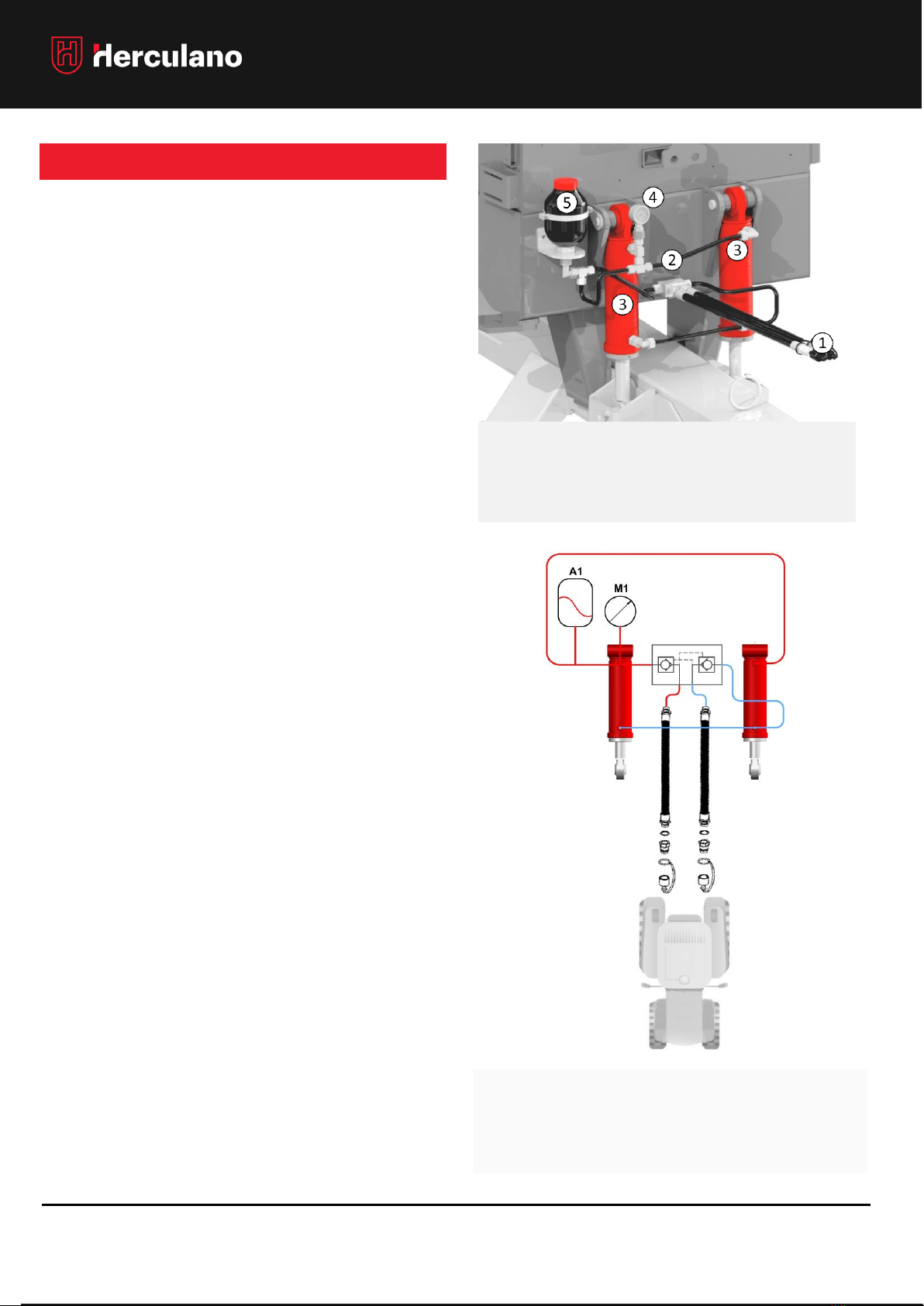
DRAWBAR'S HYDRO-PNEUMATIC SUSPENSION
(WHEN APPLICABLE)
This system allows to dampen the drawbar vibrations caused
by movement on the ground or when driving on public
roads.
In addition to this system allowing for smoother damping of
the forces exerted on the tractor’s coupler, compared to the
spring system, it also makes it possible to move to the level of
the drawbar to the tractor’s coupler.
If necessary, it also allows you to transfer more or less weight
to the tractor’s coupler, opening or closing the cylinders with
the tractor's hydraulic circuit, always bearing in mind that the
cylinders must never be completely closed, otherwise the
drawbar will remain without suspension. (Stiff)
1. In an initial stage, you must proceed with the initial
adjustment / calibration of the system in order to adapt
it to your tractor;
1.1. To do this, with the semi-trailer unloaded, align the
tractor with the drawbar and proceed with the
coupling.
1.2. Connect the hydraulic hoses of the drawbar
damping system to the tractor;
When connecting the hoses, make sure that the quick-
connect valves are clean! “
1.3. Adjust the height of the cylinders to ensure that
they are in intermediate position (halfway
approximately, if they are completely open /
closed, the drawbar will remain without suspension.
2. In case of accumulator leaking or end-of-life, the system
stops damping and becomes stiff; it must be replaced
immediately. To that end, make sure the work is done by
a qualified person or request information/manufacturer
assistance.
1 - Coupling valves - connection to the tractor
2 - Check valve –Double piloted
3 –Hydropneumatic Suspension - Cylinders
4 –Pressure gauge
5 - Accumulator
After replacing the accumulator, you must proceed
with a new initial adjustment / calibration set-up. Make
sure that you comply with point 1 again entirely.

OPERATOR’S MANUAL: HMB •HMB RG •HGMB
REV. 04.2022 20
HYDRAULIC SYSTEMS
SELF STEERING AXLES
The BOGGIE / TANDEM / TRIDEM suspension system with
self-steering axles allow to considerably reduce tire
wear, improves the vehicle's manoeuvrability, and
significantly reduces passive reactions to wheels and
chassis.
•Before starting work, make sure to connect this
system's hydraulic hose(s) to the tractor;
•Check how the stopcock(s) is(are): Open or
Closed?
•To lock or unlock the self-steering axle(s) in service,
the stopcock(s) must be open because the control
is given with the tractor lever. Whenever possible,
the axle should be locked in motion, especially
when the trailer is loaded, therefore avoiding
damage to the tires.
•You must lock the axle(s) whenever it is necessary
to perform a reversing maneuverer, or to drive on a
road above 15 or 20 km / h. In all other situations, it
must be unlocked and with the tractor lever in the
float position
•Whenever you want to uncouple the trailer from the
tractor, first turn off the stopcocks. If you don't do so,
the lines will be pressurized and you might
experience difficulties connecting the valves to the
tractor with the next connection.
NOTE: If you want to immobilize the trailer, when reversing
you must lock the axles. Otherwise, the next time you need
to work use it, you will experience difficulties to connect
the coupling valves to the tractor due to the pressurized
system.
.
FAD | AMB | ADR
Depending on the
brand, the hydraulic
operation of the self-
steering axle can have
single or double effect
CONNECT THE HYDRAULIC
HOSES TO
THE
TRACTOR!
OPEN THE STEERING
STOPCOCKS!
(WHEN APPLICABLE)
This manual suits for next models
19
Table of contents
Other FERPINTA Farm Equipment manuals


