manuals.online logo
Brands
  1. Home
  2. •
  3. Brands
  4. •
  5. Ferroli
  6. •
  7. Heating System
  8. •
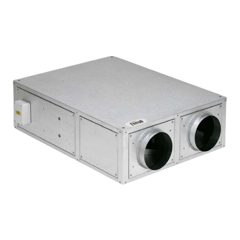
  9. Ferroli UT REC C+ Service manual

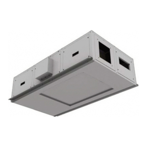
Ferroli UT REC C+ Service manual

UT REC C+ / UT REC CE+
RECUPERATORI DI CALORE
HEAT RECOVERY UNITS
MANUALE DI ISTALLAZIONE, USO E MANUTENZIONE /
INSTALLATION, USE AND MAINTENANCE MANUAL
Manuale di installazione, Uso e Manutenzione - Installation, Use and Maintenance Manual
pag. 2
INDICE INDEX
1 - SIMBOLOGIA UTILIZZATA pag. 3
2 - AVVERTENZE E REGOLE GENERALI pag. 3
3 - IDENTIFICAZIONE UNITÀ pag. 5
4 - CARATTERISTICHE TECNICHE pag. 6
4.1 Caratteristiche generali pag. 6
4.2 Accessori pag. 6
4.3 Dati tecnici unità pag. 7
4.4 Orientamenti possibili pag. 8
4.5 Funzionalità principali pag. 9
4.6 Dimensioni e pesi pag. 10
4.6.1 Dimensioni modelli UTREC C+ / UTREC CE+ pag. 10
5 - TRASPORTO pag. 11
6 - SCARICO pag. 11
6.1 Controllo al ricevimento pag. 11
6.2 Sollevamento e movimentazione pag. 11
6.3 Stoccaggio pag. 11
7 - INSTALLAZIONE E MESSA IN SERVIZIO pag. 12
7.1 Definizioni pag. 12
7.2 Norme di sicurezza pag. 12
7.3 Informazioni preliminari pag. 13
7.4 Luogo d'installazione pag. 13
7.5 Posizionamento della macchina pag. 14
7.6 Collegamento ai canali aeraulici pag. 14
7.7 Collegamenti idraulici pag. 14
7.7.1 Batteria di post riscaldamento ad acqua BCR pag. 15
7.8 Sezione con batteria ad acqua SBFR pag. 16
7.8.1 Collegamenti idraulici SBFR pag. 17
7.8.2 Collegamento scarichi condensa pag. 17
8 - COLLEGAMENTI ELETTRICI pag. 18
8.1 Accessori e caratteristiche elettriche pag. 18
8.1.1 Segnalazione filtri sporchi pag. 18
8.1.2 Controllo di velocità - COM3 pag 18
8.1.3 Ventilatori a portata costante - VSD pag. 18
8.1.4 Pannello di controllo unità - PCU pag. 19
8.1.5 Pannello di controllo unità - PCUE pag. 22
8.2 Schemi elettrici pag. 25
9 - CONTROLLI PRIMA DELL'AVVIAMENTO pag. 35
10 - MANUTENZIONE ORDINARIA pag. 35
10.1 Avvertenze pag. 35
10.2 Controlli mensili pag. 35
10.2.1 Verifica della sezione filtrante pag. 35
10.3Controlli annuali pag. 35
11 - LOCALIZZAZIONE DEI GUASTI pag. 36
12 - SMALTIMENTO pag. 36
INDEX
1 - SYMBOLS USED page 3
2 - WARNINGS AND GENERAL RULES page 3
3 - IDENTIFICATION OF THE UNIT page 5
4 - TECHNICAL SPECIFICATIONS page 6
4.1 General characteristics page 6
4.2 Options page 6
4.3 Unit technical data page 7
4.4 Possible configurations page 8
4.5 Main logic control page 9
4.6 Dimensions and whights page 10
4.6.1 Dimensions of the models UT‐REC C+ / UT‐REC CE+ page 10
5 - TRANSPORT page 11
6 - UNLOADING page 11
6.1 Checks upon receipt page 11
6.2 Hoisting and handling page 11
6.3 Storage page 11
7 - INSTALLATION AND START UP page 12
7.1 Definitions page 12
7.2 Safety Standards page 12
7.3 Preliminary information page 13
7.4 Installation location page 13
7.5 Unit positioning page 14
7.6 Horizontal units positioning page 14
7.7 Hydraulic connections page 14
7.7.1 Water post heating coil BCR page 15
7.8 Water coil section SBFR page 16
7.8.1 Hydraulic connections page 17
7.8.2 Connection of the SBFR section condensate drain page 17
8 - ELECTRIC CONNECTIONS page 18
8.1 Options and technical feateures page 18
8.1.1 Dirty filters warning page 18
8.1.2 Speed controller - COM3 page 18
8.1.3 Constant air flow fans - VSD page 18
8.1.4 Control panel - PCU page 19
8.1.5 Control panel - PCUE page 22
8.2 Wiring diagrams page 25
9 - CONTROL BEFORE START-UP page 35
10 - ORDINARY MAINTENANCE page 35
10.1 Warnings page 35
10.2 Montly checks page 35
10.2.1 Check the UT‐REC C+ / UT‐REC CE+
range filtering section page 35
10.3Yearly checks page 35
11 - IDENTIFYING BREAKDOWNS page 36
12 - DISPOSAL page 36
IMPORTANTE
PRIMA DI COMPIERE QUALUNQUE OPERAZIONE
RIGUARDANTE LA MACCHINA LEGGERE
ATTENTAMENTE, COMPRENDERE E SEGUIRE
TUTTE LE ISTRUZIONI DEL PRESENTE MANUALE
IMPORTANT
BEFORE PERFORMING ANY OPERATION OF THE
MACHINE CAREFULLY READ,
UNDERSTAND AND FOLLOW
ALL INSTRUCTIONS LISTED IN THIS MANUAL
Manuale di installazione, Uso e Manutenzione - Installation, Use and Maintenance Manual pag. 3
1 - SIMBOLOGIA UTILIZZATA 1 - SYMBOLS USED
AVVERTENZA WARNING
PERICOLO DANGER
PERICOLO RISCHIO DI SCOSSE ELETTRICHE DANGER RISK OF ELECTRIC SHOCK
ATTENZIONE SOLO PERSONALE AUTORIZZATO ATTENTION ONLY AUTHORISED STAFF
DIVIETO PROHIBITION
La macchina è stata progettata e costruita in accordo alle norme vigenti ed
è quindi dotata di sistemi di prevenzione e protezione per i rischi di natura
meccanica ed elettrica che possono riguardare l’operatore o l’utilizzatore.
Vi sono tuttavia dei rischi residui che possono presentarsi durante il tra-
sporto, l’installazione, l’uso o la manutenzione. Tali rischi possono essere
ridotti seguendo scrupolosamente le istruzioni del manuale, utilizzando gli
adeguati dispositivi di protezione individuali e rispettando le vigenti norme
di sicurezza.
Le indicazioni più importanti riguardanti la sicurezza e il corretto utilizzo
della macchina sono accompagnate da alcuni simboli per renderle più evi-
denti:
The machine has been designed and constructed according to the current
norms and consequently with mechanical and electrical safety devices
designed to protect the operator or user from possible physical damage.
Residual risks during use or in some intervention procedures on the devi-
ce are however present. Such risks can be reduced by
carefully following manual procedures, using the suggested individual pro-
tection devices and respecting the legal and safety norms in force.
The most important information concerning safety and proper use of the
machine are accompanied by some symbols to make them highly visible:
Questo libretto d'istruzione è parte integrante dell'apparecchio e di conse-
guenza deve essere conservato con cura e dovrà SEMPRE accompagna-
re l'apparecchio anche in caso di sua cessione ad altro proprietario o uten-
te oppure di un trasferimento su un altro impianto. In caso di suo danneg-
giamento o smarrimento richiederne un altro esemplare alla Ditta
Costruttrice.
This instruction book is an integral part of the appliance and as a
consequence must be kept carefully and must ALWAYS accom-
pany the appliance even if transferred to other owners or users
or transferred to another plant. If damaged or lost, request ano-
ther copy from the Manufacturer.
Gli interventi di riparazione o manutenzione devono essere eseguiti da
personale autorizzato o da personale qualificato secondo quanto previ-
sto dal presente libretto. Non modificare o manomettere l'apparecchio in
quanto si possono creare situazioni di pericolo ed il costruttore dell'ap-
parecchio non sarà responsabile di eventuali danni provocati.
Repair and maintenance interventions must be carried out by
authorised staff or staff qualified according to that envisioned by
this book. Do not modify or tamper with the appliance as dange-
rous situations can be created and the appliance manufacturer
will not be liable for any damage caused.
Dopo aver tolto l'imballo assicurarsi dell'integrità e della completezza del
contenuto. In caso di non rispondenza rivolgersi alla Ditta che ha vendu-
to l'apparecchio.
After having removed the packaging ensure the integrity and
completeness of the content. If this is not the case, contact the
Company that sold the appliance.
L'installazione degli apparecchi deve essere effettuata da impresa abili-
tata che, a fine lavoro, rilasci al proprietario la dichiarazione di confomità
di installazione realizzata a regola d'arte, cioè in ottemperanza alle
Norme vigenti ed alle indicazioni fornite in questo libretto.
The appliances must be installed by enabled companies which, at
the end of the job issues a declaration of conformity regarding
installation to the owner, i.e. in compliance with the Standards in
force and the indications supplied in this book.
È esclusa qualsiasi responsabilità contrattuale ed extracontrattuale della
Ditta Costruttrice per danni causati a persone, animali o cose, da errori
di installazione, di regolazione e di manutenzione o da usi impropri.
Any contractual or extracontractual liability ofthe Manufacturer is
excluded for injury/damage to persons, animals or objects owing
to installation, regulation and maintenance errors or improper
use.
2 - AVVERTENZE E REGOLE GENERALI 2 - WARNINGS AND GENERAL RULES
Manuale di installazione, Uso e Manutenzione - Installation, Use and Maintenance Manual
pag. 4
Ricordiamo che l'utilizzo di prodotti che impiegano energia elettrica ed acqua, comporta
l'osservanza di alcune regole fondamentali di sicurezza quali:
We remind you that the use of products that employ electrical energy and
water requires that a number of essential safety rules be followed, including:
È vietato l'uso dell'apparecchio ai bambini e alle persone inabili non
assistite.
This appliance must not be used be children and unaided dis-
abled persons.
È vietato toccare l'apparecchio se si è a piedi nudi e con parti del corpo
bagnate o umide.
It is prohibited to touch the appliance when you are barefoot
and with parts of the body that are wet or damp.
È vietata qualsiasi operazione di manutenzione o di pulizia, prima di
aver scollegato l'apparecchio dalla rete di alimentazione elettrica posi-
zionando l'interruttore generale dell'impianto su "spento".
It is prohibited to perform any maintenance or cleaning opera-
tion before having disconnected the appliance from the
mains electricity network, by positioning the plant master switch
at "off"
È vietato modificare i dispositivi di sicurezza o di regolazione senza
l'autorizzazione e le indicazioni del costruttore dell'apparecchio.
It is prohibited to modify the safety or adjustment devices
without the manufacturer’s authorisation and precise instruc-
tions
È vietato tirare, staccare, torcere i cavi elettrici fuoriuscenti dall'apparec-
chio, anche se questo è scollegato dalla rete di alimentazione elettrica.
It is prohibited to pull, detach or twist the electrical cables
coming from the unit even if it is disconnected from the electri-
cal mains
È vietato salire con i piedi sull'apparecchio, sedersi e/o appoggiarvi
qualsiasi tipo di oggetto.
It is prohibited to climb onto the unit, sit on it and/or rest any
type of object on it.
È vietato spruzzare o gettare acqua direttamente sull'apparecchio.
It is prohibited to spray or jet water directly onto the unit.
È vietato aprire gli sportelli di accesso alle parti interne dell'apparec-
chio, senza aver prima posizionato l'interruttore generale dell'impianto
su "spento" .
It is prohibited to open the doors for accessing the internal parts
of the appliance without first having switched off the master
switch of the "system".
È vietato disperdere, abbandonare o lasciare alla portata di bambini il
materiale dell'imballo in quanto può essere potenziale fonte di pericolo.
It is prohibited to disperse, abandon or leave the packing mate-
rials within the reach of children, as they are a potential
source of danger
Poiché la Ditta Costruttrice è costantemente impegnata nel conti-
nuo perfezionamento di tutta la sua produzione, le caratteristiche
estetiche e dimensionali, i dati tecnici, gli equipaggiamenti e gli
accessori, possono essere soggetti a variazione.
Per tale motivo il produttore si riserva di apportare qualsiasi
modifica senza preavviso.
As our Company is constantly involved in the continuous impro-
vement of its production, aesthetic characteristics and dimen-
sions, technical data, equipment and accessories can be subject
to variation. For this reason the manufacturer reserves the right
to make any changes without prior notice.
NOTE IMPORTANTI
Le unità sono progettate e costruite esclusivamente per:
- installazioni interne, salvo adottare idonei accessori che ne con-
sentano l’installazione all’aperto;
- per il trattamento aria degli ambienti civili, incompatibili con gas
tossici, esplosivi, infiammabili e corrosivi (incluse atmosfere con
cloro e salsedine).
Quindi se ne fa esplicito divieto di utilizzo in quegli ambienti dove
l'aria risulti mescolata e/o alterata da altri composti gassosi e/o
particelle solide.
L'utilizzo per scopi diversi da quelli previsti, e non conformi a
quanto descritto in questo manuale, farà decadere automatica-
mente qualsiasi responsabilità diretta e/o indiretta della Ditta
Costruttrice e dei suoi Distributori.
IMPORTANT NOTES
The units are designed and built exclusively for:
- internal installation, except to use specific option for outdoor
installation;
- for air traitment in the civil environments, incompatible with
toxic, explosive, inflammable and corrosive (chlorinated and sali-
ne included) gases.
Therefore it cannot be used in those environments where the air
is mixed and/or altered by other gaseous composites and/or solid
particles.
The use of the same for different purposes from those envisioned,
not conform to that described in this manual, will make any direct
and/or indirect liability of the Manufacturer automatically become
null and void.
Manuale di installazione, Uso e Manutenzione - Installation, Use and Maintenance Manual
pag. 5
3 - IDENTIFICAZIONE UNITÀ 3 - IDENTIFICATION OF THE UNIT
PER EVENTUALI RICHIESTE DI INFOMAZIONI E’ NECESSARIO
RIVOLGERSI ALLA SEDE COMUNICANDO IL NUMERO DI SERIE
DELL’UNITA’.
WHEN CONTACTING THE OFFICE FOR ANY INFORMATION ENQUI-
RIES, PLEASE PROVIDE THE UNIT SERIAL NUMBER.
Le unità sono dotate di una targhetta di identificazione che riporta:
A - Marchio del Costruttore;
B - Indirizzo del Costruttore;
C - Modello unità;
D - Matricola unità;
E - Tensione; n° fasi; frequenza di alimentazione;
F - Corrente assorbita massima;
G - Codice unità;
H - Data di produzione;
I - Marcatura “CE”;
L - Codice a barre identificativo
The units feature a rating plate that describes the following:
A - Mark of the manufacturer;
B - Address of the manufacturer;
C - Unit model;
D - Unit serial number;
E - Voltage, number of phases; frequency of the power supply;
F - Max absorbed current;
G - Unit code;
H - Manufacturinga date;
I - “CE” mark;
L - Bar code
B
A
C
D
E
F
G
H
I
L
Manuale di installazione, Uso e Manutenzione - Installation, Use and Maintenance Manual pag. 6
4 - CARATTERISTICHE TECNICHE
4.1 Caratteristiche generali
• Recuperatore di calore entalpico ad alto rendimento di tipo statico a
flussi incrociati, costruito con membrane altamente permeabili all’umidi-
tà, di elevata resistenza alla lacerazione e all’invecchiamento. Sono
interposte alternativamente piastre piane con piastre corrugate.
• Isolamento acustico e termico dei pannelli tramite poliuretano con spes-
sore medio di 20 mm
• Ventilatori di presa aria di rinnovo e di espulsione di tipo centrifugo a
doppia aspirazione
• Motore elettrico direttamente accoppiato, di tipo EC in UTREC CE+
• Filtri aria standard con efficienza F7 in mandata ed M5 in ripresa, facil-
mente estraibili lateralmente allo scopo di permettere la loro periodica
pulizia.
• La struttura portante e i pannelli laterali (tipo sandwich, rimovibili) sono
realizzati in lamiera preverniciata.
• By pass per sbrinamento o free cooling.
• Pressostato filtri aria di rinnovo con segnalazione visiva allarme filtro
sporco.
4 - TECHNICAL SPECIFICATIONS
4.1 General characteristics
• High efficiency enthalpic heat recovery, static cross flow type , made by
membrane with high moisture permeability, good air tightness, excellent tear
resistance, and aging resistance. It is structured with flat plates and corru-
gated plates.
• An average 20 mm-thick layer of polyurethane is installed in the unit to
ensure acoustic and heat insulation.
• The dual intake centrifugal fans have statically and dynamically balan-
ced impellers to minimise vibrations and noise.
• The electric motors used are directly coupled to the fans; they are EC
type on UT‐REC CE+
• Standard F7 efficiency filters for supply air side and M5 for exhaust air
side, easily removable from the sides for periodical cleaning.
• The structure and the paneling (sandwich type, removable) are made
from painted metal sheet
• The structure of models UT‐REC + features bypass section for defrost
or free cooling functions
•Pressure switch for fresh air filters with visual filter change warning light
indicator.
4.2 Accessori
• Resistenza elettrica di post-riscaldamento integrata - BER
• Batteria interna di post-riscaldamento ad acqua - BCR
• Sezione con batteria ad acqua promiscua - SBFR
• Filtri ad alta efficienza in espulsione - F7CF
• Pressostato filtri addizionale - PF
• Serranda di regolazione - SR
• Sezione 3 serrande di sbrinamento - RMS
• Servomotori per serrande - SM / SMR
• Kit gestione Bypass - KBP
• Kit n° 4 attacchi circolari - SPC
• Silenziatori da canale - SSC
• Kit lampade di segnalazione (Legge “antifumo” n° 3/2003) - KLS
• Termostato antigelo - TA
• Pannello di controllo velocità (UTREC C+ 40  320 ) - COM 3
• Pannello di controllo unità - PCU / PCUE
• Sistema di gestione integrale a bordo macchina - SIGB
• Sistema di gestione integrale con quadro a parete - SIGQ
Istruzioni del manuale dedicato fornito a corredo con l’unità
dotata di tale accessorio.
• Scheda Modbus per SIGB / Q - SCMB
• Regolazione ventilatori a portata costante (UTREC CE+ 100  320)-VSD
• Sensore di CO2- QSC / QSA
• Sensore di umidità - USD / USW
• Kit installazione da esterno - EXT
• Kit cuffie da esterno - CPA
4.2 Options
• Internal electric post-heating coil- BER
• Post-heating internal water coil - BCR
• Water cooling or heating coil section - SBFR
• High efficiency filters on exhaust air - F7CF
• Additional pressure switch - PF
• Regulation damper - SR
• 3 dampers defrosting section - RMS
• Damper actuators - SM / SMR
• Kit bypass management - KBP
• N. 4 connections for circular ducts kit - SPC
• Duct silencers - SSC
• Signal lamps kit - KLS
• Anti-freeze thermostat - TA
• Unit speed control panel (UT‐REC C+ 40 ‐ 320) - COM 3
• Unit control panel - PCU / PCUE
• Integrated management system on board - SIGB
• Integrated management system wall mount box - SIGQ
Use specific manual supplied on the unit with this option
• Modbus PCB for SIGB / Q - SCMB
• Constant air flow fans control (UT‐REC CE+ 100 ‐ 320) - VSD
•CO
2sensor - QSC / QSA
• Humidity sensor - USD / USW
• Kit for external installation - EXT
• Kit weather hood for external installation - CPA
Manuale di installazione, Uso e Manutenzione - Installation, Use and Maintenance Manual
pag. 7
4.3 Dati tecnici unità 4.3 Unit technical data
(1) Multiple = Multivelocità > 3
Man = Manuale da selettore o tastiera; 0-10V = Da potenziometro o tastiera;
VSD = A portata costante o modulazione da sensore qualità/umidità aria
(2) Livello di potenza sonora alle condizioni di funzionamento nominali
(3) Aria esterna -5°C 80% UR; aria ambiente 20°C 50% UR
(4) Aria esterna 32°C 50% UR; aria ambiente 26°C 50% UR
(5) Secondo regolamento UE 1253/2014: alla pressione nominale;
condizioni di temperatura e umidità riferite a EN 308
(1) Multiple = Multispeed > 3
Man = Manual by selector switch or control panel; 0-10V = By potentiometer or control
panel; VSD = Constant flow control or modulation by air quality or air humidity sensor
(2) Sound power level at nominal working conditions
(3) Outside air at -5° 80% RH; room air at 20°C 50% RH
(4) Outside air at 32° 50% RH; room air at 26°C 50% RH
(5) Refeer to EU 1253/2014 regulation: at nominal pressure; air conditions refer to EN
308 standard
MODELLO / MODEL 40 40 75 75 100 100 150 150 200 200 320 320
Portata aria nominale / Nominal air flow m3/h 400 400 660 660 1000 1000 1500 1500 2300 2300 3100 3100
Pressione statica utile nominale / Nominal external static pressure Pa 170 170 120 120 160 160 190 190 240 240 190 190
Pressione statica utile massima / Maximum external static pressure Pa 170 375 120 250 160 535 190 550 240 447 190 400
Alimentazione elettrica / Electrical power supply V/ph/Hz 230 / 1 / 50 230 / 1 / 50-60
Potenza assorbita massima totale / Total full load power input kW 0.35 0.56 0.68 0.56 1.41 2.12 1.41 2.12 3.29 2.12 3.29 2.35
Corrente assorbita massima totale / Total full load amperage A1.5 2.4 2.9 2.4 6.0 9.0 6.0 9.0 14.0 9.0 14.0 10.0
LIMITI OPERATIVI / WORKING LIMITS
Condizioni di temperatura - umidità limite esterne / Outdoor temperature -
humidity working limits °C / % -5 … +45 °C / 5 … 95%
Condizioni di temperatura - umidità limite esterne con accessorio RMS /
Outdoor temperature - humidity working limits with RMS option °C / % -15 … +45 °C / 5 … 95%
Condizioni di temperatura - umidità limite interne / Indoor temperature -
humidity working limits °C / % +10 … +35 °C / 10 … 90%
VENTILATORI / FANS 40 40 75 75 100 100 150 150 200 200 E 320 320
Tipologia motore / Motor typology AC EC AC EC AC EC AC EC AC EC AC EC
N° velocità / Number of speeds (1) 3 Multiple 3 Multiple 3 Multiple 3 Multiple 3 Multiple 3 Multiple
Controllo ventilazione / Fan control (1) Man 0-10V Man 0-10V Man 0-10V
VSD Man 0-10V
VSD Man 0-10V
VSD Man 0-10V
VSD
Potenza assorbita nominale totale / Total nominal power input kW 0.16 0.15 0.28 0.26 0.55 0.48 0.96 0.62 1.55 1.31 1.67 1.50
Corrente assorbita nominale totale / Total nominal load amperage A0.7 0.7 1.2 1.1 2.3 2.0 4.1 2.7 6.6 5.6 7.1 6.4
Efficienza statica dei ventilatori secondo (UE) n.327/2011 / Static effi-
ciency of fans %N.A. 32.73%38.60%32.73%38.60%53.20%38.60%53.20%40.40%55.90%43.40%59.80%
RECUPERATORE DI CALORE / HEAT EXCHANGER 40 40 75 75 100 100 150 150 200 200 320 320
Efficienza termica invernale / Winter thermal effic. (3) % 75.0% 75.0% 73.7% 73.7% 74.0% 74.0% 73.0% 73.0% 73.2% 73.2% 71.4% 71.4%
Efficienza entalpica invernale / Winter enthalpy effic. (3) % 60.0% 60.0% 58.2% 58.2% 58.8% 58.8% 62.5% 62.5% 62.7% 62.7% 55.5% 55.5%
Potenza termica totale recuperata / Total heating recovery capacity (3) kW 2.47 2.47 4.01 4.01 6.10 6.10 9.03 9.03 13.88 13.88 18.25 18.25
Temperatura aria mandata / Supply air temperature (3) °C 13.8 13.8 13.4 13.4 13.5 13.5 13.3 13.3 13.3 13.3 12.9 12.9
Efficienza termica estiva / Summer thermal effic. (4) % 64.1% 64.1% 59.7% 59.7% 60.2% 60.2% 60.1% 60.1% 60.2% 60.2% 57.4% 57.4%
Efficienza entalpica estiva / Summer enthalpy effic. (4) % 56.7% 56.7% 55.1% 55.1% 55.7% 55.7% 58.3% 58.3% 58.5% 58.5% 52.5% 52.5%
Potenza frigorifera totale recuperata / Total cooling recovery capacity (4) kW 0.52 0.52 0.79 0.79 1.21 1.21 1.81 1.81 2.79 2.79 3.58 3.58
Temperatura aria mandata / Supply air temperature (4) °C 28.2 28.2 28.4 28.4 28.4 28.4 28.4 28.4 28.4 28.4 28.6 28.6
Efficienza termica a secco / Dry thermal efficiency (5) % 75.1% 75.1% 73.7% 73.7% 74.2% 74.2% 73.1% 73.1% 73.2% 73.2% 73.0% 73.0%
Livello di potenza sonora irradiato dall'involucro / Sound power level
(LWA) (2) dB(A) 58 57 58 57 61 60 64 61 68 67 69 66
Manuale di installazione, Uso e Manutenzione - Installation, Use and Maintenance Manual pag. 8
4.4 Orientamenti possibili
In funzione della configurazione della rete e dello spazio disponibile è pos-
sibile scegliere, fra due possibili orientamenti, come di seguito illustrato.
4.4 Possibile configurations
According to the configuration of the installation and the space available,
s one of two possible layouts can be chosen, as shown below.
ORIENTAMENTI MODELLI / MODELS CONFIGURATIONS
ORIENTAMENTO TIPO 01 / CONFIGURATION TYPE 01 ORIENTAMENTO TIPO 02 / CONFIGURATION TYPE 02
Gli orientamenti raffigurati sono relativi alla macchina vista dall’alto / The configurations are referred to the top view
Aria espulsa / Exhaust air
Aria di rinnovo / Fresh air
Aria espulsa / Exhaust air
Aria di rinnovo / Fresh air
Mandata aria
Supply air
Ripresa ambiente
Return air
Free cooling
Serranda Aperta / Damper Opened
Serranda chiusa / Damper closed
Aria di rinnovo / Fresh air
Espulsione aria
Exhaust air
Disposizione tipica per Free Cooling
Free Cooling typical configuration
Aria espulsa / Exhaust air
Aria di rinnovo / Fresh air
Quadro elettrico / Electrical board
BCR / BER ( Accessori / Options )Lato destro / Right side Lato destro / Right side
BCR / BER ( Accessori / Options )
Quadro elettrico / Electrical board
Dispositivo by pass per free cooling / heating
Le Unità sono provviste di sezione apposita interna di bypass parziale
del recuperatore.
Quando la temperatura esterna è prossima alla temperatura interna si
può ridurre sensibilmente lo scambio di calore attraverso il recuperatore.
La macchina viene fornita con sistema di apertura manuale (standard) o
con servomotore opzionale: la configurazione automatizzata può esse-
re comandata attraverso un consenso esterno o dalla gestione elettroni-
ca integrata (opzionale)
Bypass device for free cooling / heating
The Units are equipped with special internal sec-tion for the bypass
function.
When the air intake temperature is near the air outlet temperature the
heat recovery unit can be partly bypassed reducing the heat exchange.
The unit could be equipped with manual opening sysyem (standard) or
with optional electric motor: the automated configuration can be mana-
ged by an external input or by integrated electronical management
(optional)
Manuale di installazione, Uso e Manutenzione - Installation, Use and Maintenance Manual
pag. 9
4.5 Funzionalità principali 4.5 Main logic control
Sbrinamento. Nei periodi molto freddi l’aria di ripresa ambiente potreb-
be brinare ostruendo il passaggio attraverso il recuperatore. Installando
un pressostato aggiuntivo e l’accessorio RMS è possibile gestire lo sbri-
namento del recuperatore. Infatti se il pressostato rileva una caduta di
pressione eccessiva dovuta alla brina che ostruisce il recuperatore, le
serrande A e B si chiudono e si apre la serranda C. In questo modo l’a-
ria calda di ripresa ambiente viene ricircolata consentendo un rapido
scongelamento del recuperatore stesso che può successivamente torna-
re al funzionamento normale.
Defrost. When the intake air is very cold, frost may form on the heat
recovery unit.
By installing an additional pressure switch with the RMS accessory, the
heat recovery defrosting can be controlled.
When the pressure loss registered by the pressure switch is too high, the
dampers A and B will close and the damper C will open.
So the warm return air is recirculated, allowing the heat exchanger defro-
sting. Afterwards the unit functioning will become normal.
Aria di rinnovo
Fresh air
Espulsione aria viziata
Exhaust air discharge
Sezione RMS / RMS section Aria espulsa / Exhaust air
Aria di rinnovo / Fresh air
Ripresa ambiente
Return air
Aria di rinnovo
Fresh air
Disposizione tipica per Sbrinamento
Defrost typical configuration
K
Manuale di installazione, Uso e Manutenzione - Installation, Use and Maintenance Manual pag. 10
4.6 Dimensioni e pesi
4.6.1 Dimensioni modelli UTREC C+ / UTREC CE+
4.6 Dimensions and weights
4.6.1 Dimensions of the models UT‐REC C+ / UT‐REC CE+
Dimensione / Dimension Peso /
Weight
Modello
Model
A
[mm]
B
[mm]
C
[mm]
D
[mm]
D1
[mm]
E
[mm]
F
[mm]
F1
[mm]
G
[mm]
G1 (¹)
Ø inch
Y
[mm]
K
[mm] [Kg]
40 1480 380 800 200 70 210 215 90 70 3/4" 115 500 80
75 1450 480 990 300 100 310 230 140 200 3/4" 140 500 120
100 1600 550 1000 300 100 410 230 145 260 3/4" 90 500 150
150 2000 680 1290 400 130 410 300 170 260 3/4" 220 600 190
200 2000 680 1290 400 50 410 330 170 290 3/4" 155 620 200
320 2100 680 1400 500 50 510 330 195 290 3/4" 155 700 220
(1) Connessioni batteria ad acqua di post-riscaldamento BCR opzionale / Connection for optional post-heating water coil BCR
Lato destro / Right side
BCR/BER (Accessori / Options)
Quadro elettrico / Electrical board
Manuale di installazione, Uso e Manutenzione - Installation, Use and Maintenance Manual
pag. 11
• Le unità trattamento aria e i loro accessori sono inseriti in scatole di car-
tone che dovranno rimanere integre fino al momento del montaggio.
• I componenti che, per esigenze tecniche, costruttive, di trasporto o qual-
sivoglia, non vengono montati a bordo macchina, ma spediti separata-
mente all’interno dell’unità o meno, vengono protetti con adeguati involucri
e debitamente menzionati sulla bolla di accompagnamento delle merci.
• Si diffida dal sovrapporre qualsiasi altro materiale sulla merce: la ditta
costruttrice declina ogni responsabilità in caso di danni derivanti da tale
carico.
• The air handling units are packed in cardboard boxes that must remain
intact until assembly.
• The components that, due to technical, constructional, transport or other
requirements are not fitted on the unit, but sent separately either inside the
unit or otherwise, are specially protected and duly described on the pac-
king list.
• No other material must be stacked on the products: the manufacturer
declines all liability in the event of damage deriving from such loads.
6 - SCARICO 6 - UNLOADING
6.1 Controllo al ricevimento
Si consiglia che al ricevimento della merce, prima dello scarico, sia effet-
tuato un controllo su tutto il materiale in consegna al fine di verificare l’esi-
stenza di eventuali danni causati dal trasporto. Gli eventuali danni devono
essere debitamente comunicati al vettore e specificati nella clausola di
riserva riportata nella bolla di accompagnamento.
6.2 Sollevamento e Movimentazione
E’ vivamente consigliato :
6.1 Checks upon receipt
When receiving the goods, before unloading, all the material delivered
must be checked to ascertain the presence of any damage caused during
transport. Any damage found must be reported to the carrier, accepting the
goods with reservation and specifying the type of damage on the delivery
documents.
6.2 Hoisting and handling
It is strongly recommended :
• Il peso di ogni singola macchina è riportato sul presente manuale.
• Evitare rotazioni senza controllo.
• Appoggiare con prudenza la merce in modo da evitarne bruschi spo-
stamenti o, peggio, cadute.
• The weight of the units is shown on this manual
• Avoid uncontrolled rotations
• Place the goods down with care, avoiding sudden movements or,
worse, dropping the goods.
6.3 Stoccaggio
In caso di stoccaggio prolungato prima dell’installazione, le macchine
dovranno essere protette dalla polvere, dalle intemperie e tenute lontane
da fonti di calore e vibrazioni.
6.3 Storage
In the event of extended storage before installation, keep the units protec-
ted from dust and bad weather and away from sources of vibrations and
heat.
IL FISSAGGIO DEL CARICO SUL CAMION È A CARICO DEL TRA-
SPORTATORE È DEVE ESSERE ESEGUITO, CON CORDE O CIN-
GHIE, IN MANIERA DA NON DANNEGGIARE L’INVOLUCRO.
THE FASTENING OF THE LOAD ON THE TRUCK IS THE RESPONSI-
BILITY OF THE CARRIER, AND MUST BE PERFORMED, USING
STRAPS OR ROPES, SO AS TO AVOID DAMAGING THE PACKAGING
5- TRASPORTO 5- TRANSPORT
PER LA MOVIMENTAZIONE UTILIZZARE, IN FUNZIONE DEL PESO,
MEZZI ADEGUATI COME PREVISTO DALLA DIRETTIVA 89/391/CEE
E SUCCESSIVE MODIFICHE
WHEN HANDLING THE UNITS, USE SUITABLE MEANS ACCORDING
THE WEIGHTS INVOLVED, AS ENVISAGED BY EC DIRECTIVE
89/391 AND SUBSEQUENT AMENDMENTS
LA DITTA COSTRUTTRICE DECLINA OGNI RESPONSABILITÀ PER
DANNEGGIAMENTI DELLA MERCE DOVUTI AD UNO SCARICO NON
CORRETTO O A NON ADEGUATA PROTEZIONE DALLE INTEMPERIE
THE MANUFACTURER DECLINES ALL LIABILITY FOR DAMAGE
DERIVING FROM INCORRECT UNLOADING OR INADEQUATE PRO-
TECTION OF THE UNITS AGAINST THE ELEMENTS.
Manuale di installazione, Uso e Manutenzione - Installation, Use and Maintenance Manual pag. 12
7.1 Definizioni
UTENTE - L'utente è la persona, l'ente o la società, che ha acquistato o
affittato la macchina e che intende usarla per gli scopi concepiti.
UTILIZZATORE / OPERATORE - L'utilizzatore o operatore, è la persona
fisica che è stata autorizzata dall'utente a operare con la macchina.
PERSONALE SPECIALIZZATO - Come tali, si intendono quelle persone
fisiche che hanno conseguito uno studio specifico e che sono quindi in
grado di riconoscere i pericoli derivati dall'utilizzo di questa macchina e
possono essere in grado di evitarli.
7.1 Definitions
CUSTOMER - The customer is the person, the agency or the company
who bought or rented the unit
USER / OPERATOR - The operator or user is the physical person who
uses the unit for the purpose for which it was designed
SPECIALISTIC STAFF - It is composed by the physical trained persons,
able to recognize any danger due to the proper and improper use of the
unit and able to avoid or repair it.
inflammable or toxic gases at a high temperature.
• Nelle operazioni di installazione, usare un abbigliamento idoneo e antinfortuni-
stico, ad esempio: occhiali, guanti, ecc. come indicato dalle normative vigenti.
• Durante l'installazione operare in assoluta sicurezza, ambiente pulito e
libero da impedimenti.
• Rispettare le leggi in vigore nel Paese in cui viene installata la macchi-
na, relativamente all'uso e allo smaltimento dell'imballo e dei prodotti
impiegati per la pulizia e la manutenzione della macchina, nonché
osservare quanto raccomanda il produttore di tali prodotti.
• Prima di mettere in funzione l'unità controllare la perfetta integrità dei
vari componenti e dell'intero impianto.
• Evitare assolutamente di toccare le parti in movimento o di interporsi tra
le stesse.
• Non procedere con i lavori di manutenzione e di pulizia, se prima non è
stata disinserita la linea elettrica.
• La manutenzione e la sostituzione delle parti danneggiate o usurate
deve essere effettuata solamente da personale specializzato eseguen-
do le indicazioni riportate in questo manuale.
• Le parti di ricambio devono corrispondere alle esigenze definite dal
Costruttore.
• In caso di smantellamento dell’unità, attenersi alle normative antinqui-
namento previste.
N.B. L'installatore e l'utilizzatore nell'uso dell’unità devono tenere conto e
porre rimedio a tutti gli altri tipi di rischio connessi con l'impianto. Ad esempio
rischi derivanti da ingresso di corpi estranei, oppure rischi dovuti al convo-
gliamento di gas pericolosi infiammabili o tossici ad alta temperatura.
• Wear suitable and accident-prevention clothing during installation, for
example: goggles, gloves etc. as indicated in the current regulation
• During installation operate in complete safety, clean environment and
free from obstructions.
• Respect the laws in force, in the country in which the machine is instal
led, relative to use and disposal of packaging and the products used for
cleaning and maintenance of the machine, as well as complying with that
recommended by the producer of these products.
• Before starting the unit, check the perfect integrity of the various compo-
nents of the entire plant.
• Do not touch moving parts or intervene between these.
• Do not perform maintenance and cleaning until the electric line has been
connected.
• The maintenance and replacement of damaged or worn parts must only
be performed by specialised staff and following the indications given in
this manual.
• The spare parts must correspond to the requirements defined by the
Manufacturer.
• If the unit must be dismantled, follow the envisioned anti-pollution stan-
dards.
N.B. When using the unit, the installer and user must consider and solve
all risks connected to theplant. For example, risks deriving from the entry
of foreign bodies or risks due to the conveying of dangerous inflammable
or toxic gases at a high temperature.
LA DITTA COSTRUTTRICE DECLINA QUALSIASI RESPONSABILITÀ
PER LA MANCATA OSSERVANZA DELLE NORME DI SICUREZZA E
DI PREVENZIONE DI SEGUITO DESCRITTE. DECLINA INOLTRE
OGNI RESPONSABILITÀ PER DANNI CAUSATI DA UN USO IMPRO-
PRIO DELL’UNITÀ E/O DA MODIFICHE ESEGUITE SENZA AUTORIZ-
ZAZIONE.
THE MANUFACTURER DECLINES ALL RESPONSIBILITY FOR THE
FAILURE TO COMPLY WITH THE SAFETY AND ACCIDENT-PRE-
VENTION STANDARDS DESCRIBED BELOW.
IT ALSO DECLINES ALL LIABILITY FOR DAMAGE CAUSED BY
IMPROPER USE OF THE UNIT AND/OR MODIFICATIONS PERFOR-
MED WITHOUT AUTHORISATION.
L'INSTALLAZIONE DEVE ESSERE EFFETTUATA DA PERSONALE
SPECIALIZZATO. SPECIALISED STAFF MUST PERFORM INSTALLATION.
7 - INSTALLAZIONE E MESSA IN SERVIZIO 7 - INSTALLATION AND START UP
7.2 Norme di sicurezza 7.2 Safety Standards
Manuale di installazione, Uso e Manutenzione - Installation, Use and Maintenance Manual
pag. 13
7.3 Informazioni preliminari 7.3 Preliminary information
• Operare rispettando le norme di sicurezza in vigore, accertandosi della suf-
ficiente libertà di movimento e della pulizia degli ambienti di installazione
• Usare idoneo abbigliamento antinfortunistico e dispositivi individuali di
protezione (occhiali, guanti, ecc.)
• Trasportare la sezione imballata il più possibile vicino al luogo di instal-
lazione
• Non sovrapporre attrezzi o pesi sull'unità imballata
• Non usare l'unità come deposito per attrezzi di cantiere
•Evitare di toccare le parti mobili e di usare le stesse come punti di sol-
levamento/movimentazione
• Verificare la perfetta integrità dei vari componenti dell'unità
• Work while meeting the current safety regulations, ensuring sufficient
space to move and the cleanliness of jobsite
• Wear protective clothing and personal protective equipment (glasses,
gloves, etc.)
• Move the packed section as close as possible to the place of installa-
tion
• Don't place tools or other jobsite equipment over the packed unit
• Don't use the unit as a store of yard tools
• Don't touch moving parts and don't use them as supports
• Check the full integrity of all unit components
• Verificare che il piano di appoggio o di sostegno sia in grado di sop-
portare il peso della(e) macchina(e) e tale da non causare vibrazioni.
• Verificare che il piano di appoggio o di sostegno sia perfettamente
orizzontale onde permettere il corretto accoppiamento delle varie
sezioni.
• Non posizionare l’unità in locali in cui siano presenti gas infiammabili,
sostanze acide, aggressive e corrosive che possono danneggiare i
vari componenti in maniera irreparabile.
• Prevedere spazi tecnici adeguati tali da garantire le operazioni di
installazione nonché di manutenzione e di sostituzione dei compo-
nenti quali batterie, filtri ecc.
• Nell’eventualità che la macchina debba essere installata sospesa
bisogna prevedere un sistema di aggancio a soffitto per ciascuna delle
sezioni che compongono l’unità di trattamento.
• Make sure that the support surface is able to support the weight of the
unit(units) and will not cause vibrations.
• Make sure that the support surface is perfectly horizontal so as to
Allow the correct coupling of the various sections.
• Never position the unit in rooms where there are flammable gases or
acidic, aggressive or corrosive substances that may irreparably
damage the various components.
• Leave a minimum amount of free space around the unit, as shown in
the figure, so as to allow for installation, maintenance and the repla-
cement of components, such as coils, filters etc.
• If the unit is hung from the ceiling all the sections that make up the
air handling unit must be connected to the ceiling.
7.4 Luogo d'installazione 7.4 Installation location
Serie UTREC C+ / UTREC CE+ UT‐REC C+ / UT‐REC CE+ series
Modello
Model A (mm) B (mm)
40 450 250
75 500 300
100 500 450
150 550 450
200 650 500
320 700 550
min.500 A
300*
min. 500 A
300
Aria espulsa / Exhaust air
Aria di rinnovo / Fresh air
B
Manuale di installazione, Uso e Manutenzione - Installation, Use and Maintenance Manual pag. 14
• Le operazioni di installazione e collegamento delle tubazioni idrauliche
sono operazioni che possono compromettere il buon funzionamento
dell'impianto o, peggio, causare danni irreversibili alla macchina. Queste
operazioni sono da effettuarsi solo da personale specializzato.
• The installation and connection operations of the hydraulic pipes are
operations that can compromise the good functioning of the plant or
worse, cause irreversible damage to the machine. These operations
must only be performed by specialised staff.
• I canali devono essere dimensionati a funzione dell’impianto e delle
caratteristiche aerauliche dei ventilatori dell’unità. Un errato calcolo delle
canalizzazioni causa perdite di potenza o l’intervento di eventuali dispo-
sitivi presenti sull’impianto.
• Per prevenire la formazione di condensa ed attenuare il livello di rumo-
rosità si consiglia di utilizzare canali coibentati.
• Per evitare di trasmettere le eventuali vibrazioni della macchina in
ambiente, è consigliato interporre un giunto antivibrante fra le bocche
ventilanti e i canali. Deve comunque essere garantita la continuità elet-
trica fra canale e macchina tramite un cavo di terra.
• The ducts must be dimensioned depending on the plant and the
aeraulic features of the unit fans. An incorrect calculation of the duc-
ting causes a loss of power or the intervention of any devices present
on the plant.
• It is recommended to use insulated ducts to prevent the formation of
condensate and attenuate the noise level.
• To prevent transmission of any machine vibrations into the environ-
ment it is recommended top lace an anti-vibration joint between the
fan vents and the ducts. The electrical continuity must however be
guaranteed between the duct and the machine via the earth cable.
Qui di seguito sono illustrate alcune sequenze del montaggio:
1. Eseguire la foratura a soffitto e fissare i tiranti filettati M8 come indica-
to in figura.
2. Posizionare l'unità sui tiranti
3. Bloccare l'unità serrando i bulloni di fissaggio.
Some assembly sequences are illustrated below:
1. Drill the ceiling and fix M8 threaded tie-rods, as indicated in the figu-
re.
2. Position the unit on the tie-rods
3. Block the unit by fastening the fixing bolt
IMPORTANTE: SI FA DIVIETO DI METTERE IN FUNZIONE
L'UNITÀ SE LE BOCCHE DEI VENTILATORI NON SONO CANA-
LIZZATE O PROTETTE CON RETE ANTINFORTUNISTICA
SECONDO LE NORMATIVE VIGENTI.
IMPORTANT: IT IS PROHIBITED TO START THE UNIT IF THE
FAN VENTS ARE NOT DUCTED OR PROTECTED WITH ACCI-
DENT-PREVENTION MESH ACCORDING TO THE CURRENT
REGULATION.
7.5 Posizionamento della macchina 7.5 Positioning of the machine
7.6 Collegamento ai canali 7.6 Connection to the ducts
7.7 Collegamenti Idraulici 7.7 Hydraulic connections
Modello / Model 40 75 100 150
200
320
A (mm) 1445 1415 1565 1965 1965 2065
B (mm) 855 1045 1055 1345 1345 1455
C (mm) /595 680 760 760 760
D (mm) /475 475 550 550 550
Tirante
Tie road
Antivibrante
Antivibrating
Dado / Nut
Rondella / Washer
Staffa / Stirrup
Rondella / Washer
Dado / Nut
Dado / Nut
A
C
D
B
Manuale di installazione, Uso e Manutenzione - Installation, Use and Maintenance Manual
pag. 15
• L'eventuale batteria di post-riscaldamento ad acqua BCR è fornita di
attacchi "maschio" con filettatura GAS
• Le operazioni di serraggio vanno effettuate con cautela per evitare
danneggiamenti dei collettori in rame della batteria
• Il percorso dei tubi deve essere studiato in modo da non creare ostacoli
in caso di estrazione della batteria dell'unità
• Entrata e uscita acqua devono essere tali da consentire lo scambio
termico in controcorrente: seguire quindi le indicazioni delle targhette
ENTRATA ACQUA e USCITA ACQUA
• Prevedere una valvola di sfiato in alto ed una di scarico in basso.
• Staffare adeguatamente i tubi all'esterno della unità per evitare di sca-
ricarne il peso sulla batteria
• A collegamento effettuato spingere bene la guarnizione esterna in
gomma contro il pannello per evitare trafilamenti d'aria
• La coibentazione deve giungere a filo pannello per evitare pericolo di
scottature
• Prevedere, a livello di regolazione, l'intercettazione della batteria lato
tubi a ventilatore spento per evitare surriscaldamento dell'interno della
centrale con possibile danneggiamento di alcuni componenti
• Prevedere valvole di intercettazione per isolare la batteria dal resto dei
circuito in caso di manutenzione straordinaria.
• Prevedere dispositivo antigelo
• Nel caso di installazione in zone con climi particolarmente freddi, svuo-
tare l'impianto in previsione di lunghi periodi di ferma dell'impianto
• Possible water heating coil is provided with gas threaded male connection
• Fixing shall be carried out carefully without any damage on coil headers
• Pipeline shall be designed so that coil can be easily removed
• Follow instructions “Water IN” and “Water OUT” to connect water
pipes properly
• Coil headers or pipeline shall be provided with both upper air valve and
lower water discharge valve
• Coil headers shall not be used as support for pipes; pipes shall be sup-
ported by proper fixing system
• After connecting headers, press the external rubber gasket against the
coil panel to avoid air leakage
• Heat insulation of the pipes shall be up to panel wall to avoid burns
• (questa sarebbe da togliere, è contorta e pertinente solo se c’è un
riscaldatore di tipo elettrico)
• Provide pipeline with shut-off water valves in the event of unscheduled
maintenance
• Add antifreeze in the water circuit; empty water circuit in the event of
unit not running for long time at very cold weather condition
7.7.1 Batteria di post riscaldamento ad acqua BCR 7.7.1 Water post-heating coil BCR
Manuale di installazione, Uso e Manutenzione - Installation, Use and Maintenance Manual pag. 16
7.8 Sezione con batteria ad acqua SBFR
A corredo della sezione con batteria ad acqua è fornita una busta di plastica
contenente:
1. n. 4 antivibranti
2. n. 4 staffe di aggancio
3. n. 8 viti M8 x 20
4. n. 4 rondelle dentate diam. 8 mm.
Tale materiale trova applicazione in caso di connessione diretta all’unità
base nella sola configurazione orizzontale; per l’unità verticale, la sezio-
ne deve essere necessariamente canalizzata.
Posizionamento
• La sezione con batteria ad acqua deve essere posizionata di fronte
alla bocca di mandata della macchina. Il collettore contrassegnato dal-
l’etichetta “USCITA ACQUA” deve trovarsi dal lato della macchina (1)
• Rimuovere il pannello laterale della sezione con batteria ad acqua,
svitando le viti di fissaggio (2)
• Avvitare parzialmente 4 viti M8 negli inserti presenti ai vertici della
bocca della macchina (3)
• Agganciare la sezione con batteria ad acqua alla macchina facendo
passare la testa delle viti sporgenti attraverso i fori a chiave e spinge-
re verso il basso la sezione, in modo tale che la testa della vite risulti
bloccata nella parte superiore del foro a chiave. Accedere alle 4 viti di
fissaggio dal fianco della sezione e serrarle (4)
• Fissare nuovamente il fianco della sezione (5)
3.8 Water coil section SBFR
A plastic bag is also supplied with the section with water coil. It contains:
- n. 4 anti-vibration mounts
- n. 4 attachment brackets
- n. 8 M8 x 20 screws
- n. 4 notched washers diam. 8 mm.
This kit is to be used in case of direct connection to horizontal unit
only; for vertical unit, the section shall be ducted.
Positioning
• The section with water coil must be positioned in front of the machine
flow vent. The collector marked by the "WATER OUTLET" label must
be at the side of the machine (1)
• Remove the side panel of the section with water coil, loosening the
screw fasteners (2)
• Partially tighten the 4 M8 screws into the inserts present at the tops of
the machine event (3)
• Hitch the section with water coil to the machine, passing the head of
the projecting screws through the holes and push the section down, in
a way that the head of the screws is blocked in the upper part of the
hole. Access the 4 screw fasteners from the side of the section and
tighten them (4)
• Fix the side of the section again (5)
Attenzione: l’installazione della sezione con batteria ad acqua compor-
ta perdite di carico aggiuntive nel circuito di immissione. Attention: the installation of the section with water coil leads to additio-
nal pressure drops in the introduction circuit.
Fissaggio a soffitto
• Fissare alla sezione le staffe fornite a cor-
redo, mediante 4 viti M8 da avvitare negli
appositi inserti (6)
• Fissare a soffitto quattro tiranti filettati M8,
in corrispondenza delle staffe. Bloccare
l’unità serrando i bulloni di fissaggio (7)
Ceiling fixture
• Fix the supplied brackets to the sec-
tion using the 4 M8 screws to betigh-
tened in the relevant inserts (6)
• Fix four threaded M8 tie-rods to the
ceiling in correspondence withthe
brackets. Block the unit by tightening
the fixing bolts (7)
12 3
45 6
Rondella/Washer
Dado/Nut
Dado / Nut
Dado / Nut
Antivibrante/Antivibrating
Staffa/Stirrup
Rondella/Washer
Tirante/Tie road
7
Manuale di installazione, Uso e Manutenzione - Installation, Use and Maintenance Manual
pag. 17
7.8.1 CollegamentI idraulici sezione SBFR
• Le operazioni di installazione e collegamento delle tubazioni sono
operazioni che possono compromettere il buon funzionamento del-
l'impianto o, peggio, causare danni irreversibili alla macchina.
Queste operazioni sono da effettuarsi da personale specializzato.
• L'eventuale sezione con batteria ad acqua è fornita di attacchi
"maschio" con filettatura gas.
• Le operazioni di serraggio vanno effettuate con cautela per evitare
danneggiamenti dei collettori in rame della batteria.
• Il percorso dei tubi deve essere studiato in modo da non creare osta-
coli in caso di estrazione della batteria dell'unità.
• Entrata e uscita acqua devono essere tali da consentire lo scam-
bio termico in controcorrente: seguire quindi le indicazioni delle tar-
ghette ENTRATA ACQUA e USCITA ACQUA.
• Prevedere una valvola di sfiato in alto ed una di scarico in basso.
• Staffare adeguatamente i tubi all'esterno della sezione per evitare
di scaricarne il peso sulla batteria.
• A collegamento effettuato spingere bene la guarnizione esterna in
gomma contro il pannello per evitare trafilamenti d'aria.
• La coibentazione deve giungere a filo pannello per evitare perico-
lo di condensazioni.
• Prevedere dispositivo antigelo.
• Prevedere valvole di intercettazione per isolare la batteria dal resto
dei circuito in caso di manutenzione straordinaria.
• Nel caso di installazione in zone con climi particolarmente freddi, svuo-
tare l'impianto in previsione di lunghi periodi di ferma dell'impianto.
7.8.2 Collegamento scarico condensa sezione SBFR
• La vasca di raccolta condensa in acciaio inox e provvista di scarico
con connessione G 1/2” maschio.
• Il sistema di scarico deve prevedere un adeguato sifone per pre-
venire l'indesiderata entrata d'aria nel sistema in depressione. Tale
sifone risulta inoltre utile per evitarel'infiltrarsi di odori o insetti
• Il dimensionamento e l'esecuzione del sifone deve garantire che
H>P, dove P espresso in mm.c.a, e pari alla pressione statica utile
della macchina installata
• Il sifone deve infine essere dotato di tappo per la pulizia nella parte
bassa o deve comunque permettere un veloce smontaggio per la
pulizia
• Il percorso del tubo di scarico condensa deve avere sempre un
pendenza verso l’esterno.
• Assicurarsi che il tubo per il deflusso della condensa non solleciti
l’attacco di scarico dell’unita.
7.8.1 SBFR section hydraulic connections
• The installation and connection operations of the pipes are opera-
tions that can compromise the good functioningof the plant or
worse, cause irreversible damage to the machine. These opera-
tions must only be performed by specialisedstaff.
• The section with water coil is supplied with "male" connections with
gas threading.
• Tightening must be performed carefully to prevent damage to the
copper collectors in the coil.
• The route of the pipes must be studied in a way not to create obsta-
cles if the unit coil is extracted.
• Water inlet/outlet must be such to allow countercurrent heat
exchange: follow the indications of the WATER INLET and WATER
OUTLET plates
• Envision a high vent valve and a low discharge valve.
• Clamp the pipes adequately to the outside of the section to prevent
the weight being unloaded onto the coil.
• When connection has been made, push the external gasket well
against the panel to prevent seepage of air.
• Insulation must be flush to the panel in order to prevent the danger
of condensation.
• Envision anti-freeze device.
• Envision on-off valves to isolate the coil from the rest of the circuit
in the case of extraordinary maintenance.
• In the case of installation in zones with particularly cold climates,
empty the plant for long standstill periods.
7.8.2 Connection of the SBFR section condensate drain
• The stainless steel condensate drip tray has a drain with gas con-
nection G 1/2”.
• The drain system must have a suitable siphon in order to prevent
the undesired entry of air into the depressurised system. This
siphon is also useful to prevent the infiltration of odours or insects.
• The dimensioning and version of the siphon must guarantee
thatH>P, where P is expressed in mm.w.c and equal to the useful
static pressure of the machine installed
• The siphon must finally have a cap for cleaning the lower part or
must however allow quick disassembly for cleaning
• The route of the condensate drain pipe must always slope towards
the outside
• Make sure that the condensate flow pipe does not stress the unit
drain connection.
Livello vasca condensa
Drip tray level
Manuale di installazione, Uso e Manutenzione - Installation, Use and Maintenance Manual pag. 18
8 - COLLEGAMENTI ELETTRICI
• I collegamenti elettrici ai quadri di comando devono essere effettuati
da personale specializzato secondo gli schemi forniti.
• Assicurarsi che la tensione e la frequenza riportate sulla targhetta cor-
rispondano a quelle della linea elettrica di allacciamento.
• Per l'alimentazione generale del recuperatore non è consentito l'uso
di adattatori, prese multiple e/o prolunghe.
• E' dovere dell'installatore prevedere il montaggio il più vicino
possibile all'unità del sezionatore dell'alimentazione e quanto
necessario per la protezione delle parti elettriche.
• Collegare l'unità ad una efficace presa di terra, utilizzando l'apposita
vite inserita nell'unità stessa.
8 - ELECTRIC CONNECTIONS
• The electric connections to the control board must be made by spe-
cialised staff according to the diagrams supplied.
• Make sure that the voltage and the frequency stated on the plate cor-
respond with those of the electric connectionline.
• The use of adapters, multiple sockets and/or extensions is not allowed
to power the heat recovery unit.
• It is the installer's responsibility to assemble the unit as near as
possible to the power supply isolator andthe necessary to pro-
tect the electric parts.
• Connect the unit to an efficient earth socket, using the relevant screw
inserted in the unit itself.
8.1.2 Controllo di velocità COM 3
1. Con un cacciavite sganciare la calotta dal fermo laterale e sfilarla
2. Fissare la basetta a muro, a circa 1,5 metri dal pavimento
3. Effettuare i collegamenti elettrici
4. Riposizionare la calotta e riagganciarla sui fermi laterali.
8.1.2 Speed controller COM 3
1. Take out the cap
2. Fix the terminal strip to the wall, approximately 1,5 meters from the floor
3. Carry out the electrical connections
4. Position the cap again.
8.1.1 Segnalazione filtri sporchi
La segnalazione riguardante la necessità di eseguire la pulizia dei filtri
viene data (nelle unità non provviste di regolatore PCUE o SIG) da una
spia posta lateralmente nella scatola elettrica dell’unità. Tale spia è nor-
malmente spenta che si illumina al raggiungimento del set point di 150
Pa impostato sul pressostato che controlla l’intasamento dei filtri.
Per le unità provviste di regolatore PCUE o SIG, si ha indicazione a video
della indicazione di filtri sporchi.
8.1.1 Dirty filter warning
Warning about dirty filters and needs of cleaning them is given by a indi-
cator light placed on side of electrical box (for units not equipped whit
PCUE or SIG controller). Indicator light is normally switched off and when
pressure switch reach set point of 150 Pa indicator light switched on.
Unit equiped with is you PCUE o SIG controller shown warning about
dirty filters directly in visualizzation screens.
Prima di iniziare qualsiasi operazione assicurarsi che la
linea di alimentazione generale sia sezionata Before starting any operation, make sure that the main
power supply line has been isolated
Eseguire il collegamento con cavi di sezione adeguata alla potenza
impegnata e nel rispetto delle normative locali. La loro dimensione
deve comunque essere tale da realizzare una caduta di tensione in
fase di avviamento inferiore al 3% di quella nominale
Make the connection using cables with suitable section for the
power used and in compliance with the local regulations. Their
dimension must be such to realise a voltage drop in the start-up
phase, lower by 3% of the nominal value
Alimentazione:
Power supply: 230 -15/+10% Va.c; 50Hz
Regolazioni:
Adjustments:
Commutatore manuale: Off / Raffrescamento / Riscaldamento
Commutatore tre velocità: Min / Med / Max
Off / Cooling / Heating manual switch
3 - speed switch: Min / Med / Max
Max carico collegabile:
Max load: 5A a/at 250V a.c.
Grado di protezione:
Enclosure protection: IP 30
Temp. di funzionamento:
Operating temperature: 0°C -40°C
8.1 Accessori e caratteristiche elettriche 8.1 Options and technical features
8.1.3 Ventilatori a portata costante VSD
(solo per UTREC CE+ 100  320)
Con questo accessorio l’unità si adatta automaticamente alle caratteri-
stiche dell’impianto e la portata d’aria, pre-impostata in fabbrica,
è mantenuta costante al variare delle perdite di carico dovute, ad esem-
pio, allo sporcamento progressivo dei filtri. Il ventilatore varierà il nume-
ro di giri di conseguenza, all’interno del suo range di funzionamento.
N.B. è importante specificare il valore della portata d’aria desidera-
ta per ciascun flusso in fase d’ordine.
Per le taglie 100 - 320 il dispositivo è compreso nel driver del ventila-
tore: per successive modifiche della portata d’aria è necessario collega-
re il driver del ventilatore ad un PC, tramite apposito software da richie-
dere al fabbricante.
8.1.3 Constant air flow fans (only UT‐REC CE+ 100 ‐ 320)
With this option unit will adapt to features of installation. Air flow rate will-
be keeped constant to different pressure drop that change for example to
progressive dirty filters. Fan will change speed as consequence of dirty
filter (until his performance range remain in the valid zone).
It is important to have order with desired flow air rate.
Size from 100 to 320 option is inside in driver fan, to change value of
setted flow rate is necessary connect to fan a PC with dedicated softwa-
re.
Manuale di installazione, Uso e Manutenzione - Installation, Use and Maintenance Manual
pag. 19
8.1.4.2 Interfaccia controllo uutente PCU 8.1.4.2 PCU user control interface
8.1.4.3 Funzione dei tasti
• Il tasto On/Off (1) permette l’accensione/spegnimento dell’unità.
• Il tasto Modo/Menù (2) permette di commutare tra modo di funziona-
mento riscaldamento/raffrescamento con unità accesa, con unità
spenta unitamente al tasto ventilazione permette di accedere ai para-
metri installatore.
• Il tasto ventilazione (3) permette di selezionare tra le velocità
min/med/max e auto dei ventilatori ad unità. accesa, mentre ad unità
spenta permette unitamente al tasto Modo/Menù di accedere ai
paramtri installatore.
• Il tasto freccia giù (4) ed il tasto freccia su (5) permettono di modifica-
re il set point di temperatura.
8.1.4.3 Button functions
• The On / Off button (1) allows to power unit on / off.
• The Mode / Menu key (2) allows switching between the heating /
cooling operation of the unit is on, with unit switched off together with
the ventilation button allows access to the installer parameters.
• The ventilation button (3) allows you to select between speed min /
med / max and car fans to unity. on, while the unit is off allows toge-
ther with the Mode / Menu button to access paramtri installer.
• The down key (4) and the Up key (5) allow you to change the set
point temperature.
Display:
Dimensioni / Dimensions
86x83x13mm
Unità potenza /power unit:
Dimensioni / Dimensions
120x70x45mm
1. Pulsante On/Off
2. Pulsante Modo/Menù
3. Pulsante ventilazione
4. Pulsante freccia giù
5. Pulsante freccia su
6. Area simboli ventilazione
7. Area scritta Room/Set
8. Area modo operativo
9. Area simbolo manuale
10. Area fasce orarie
11. Area orologio
1. On/Off button
2. Mode/Menù button
3. Ventilation button
4. Down button
5. Up button
6. Ventilation display area
7. Room/set icon
8. Operative mode selected
9. Manual mode selecte
10. Time zones display area
11. Clock
8.1.4 Pannello di controllo unità - PCU
• II sistema di controllo PCU si compone di 2 parti, un display LCD,
montabile su scatola ad incasso due moduli ed una unità di potenza
nella quale sono contenutì i relè di interfaccia da collegare ai disposi-
tivi da comandare.
8.1.4 Control panel - PCU
•The PCU control system consists of two parts, an LCD display moun-
ted on a flush mounting box 2 modules and a power unit in which are
contained the interface relays to be connected to the devices to be
controlled.
8.1.4.1 Installazione controllo remoto - PCU
• Per fissare il controllo alla scatola elettrica
1. sganciare la placca frontale del controllo, agendo delicatamente sui
fermi ad incastro posti sulla parte inferiore
2. fissare con due viti la base del controllo alla scatola elettrica
3. riposizionare la placca frontale
• Per fissare l’unità di potenza alla scatola elettrica:
1. sganciare la barra di fissaggio posteriore dell’unità, agendo delicata-
mente sui fermi ad incastro posti sulla parte laterale
2. fissare con due viti la barra del controllo alla scatola elettrica
3. riposizionare la unità di potenza.
8.1.4.1 Remote control installation - PCU
• To attach the control to the electrical box:
1. unhook the front plate of the control, gently blowing on the latches
snap seats on the bottom
2. attach with two screws the basis of monitoring the electrical box
3. reposition the front plate
• To fix the power unit to the electrical box:
1. unhook the rear attachment rod, gently blowing on the latches snap
seats on the side
2. attach with two screws of the control bar to the electrical box
3. replace the power unit.
6
7
8
9
10
11
1 2 3 4 5
Manuale di installazione, Uso e Manutenzione - Installation, Use and Maintenance Manual pag. 20
8.1.4.4 Descrizione funzionamento
Il sistema di controllo PCU è un termostato in grado di comandare unità
di ventilazione a tre velocità, delle elettrovalvole 230V on/off ed una ser-
randa di bypass 230V on/off.
E’ inoltre dotato di un orologio interno con la possibilità di programmare
due fasce orarie di accensione/spegnimento e impostazione set point per
tre diversi tipi di fasce orarie: settimanale lunedì-venerdì (giorni da 1 a 5),
sabato (giorno 6) e domenica (giorno 7).
All’unità di controllo PCU vanno collegate due sonde di temperatura
esterna di tipo NTC 10k per la gestione della serranda di bypass.
Unitamente alla sonda interna al display, si hanno complessivamente tre
valori di temperatura visualizzati.
Il funzionamento delle ventilazione è regolato manualmente con apposi-
to tasto ventilazione (3) o automaticamente se selezionata la modalità
auto, in quest’ultimo caso le velocità cresceranno all’allontanarsi della
temperatura rilevata rispetto al set point impostato.
Le valvole riscaldamento/raffrescamento vengono attivate, a seconda
della modalità di funzionamento scelta, in funzione della differenza tra il
set point impostato e la sonda di regolazione scelta, che può essere la
sonda locale sul controllo o una delle due sonde esterne.
Durante il normale funzionamento sul display appare nell’area indicata
dal numero (7) la scritta ROOM, ed il valore di temperatura visualizzato
è quello della sonda locale a bordo dell’unità, se si preme e si tiene pre-
muto il tasto freccia su, la visualizzazione passa alla temperatura misu-
rata dalla sonda 1 (al posto dell’orologio appare la dicitura ntc1), rila-
sciando e premendo nuovamente freccia su, si ha la visualizzazione
della sonda 2 (dicitura ntc2).
La visualizzazione torna al valore di default dopo circa 5 secondi di man-
canza di pressione tasti.
Se si preme brevemente il tasto Modo/Menù si passa dalla modalità
riscaldamento/raffrescamento e viceversa.
L’azionamento dell’uscita di bypass avviene in modo differente a secon-
da della modalità di funzionamento:
- Durante il funzionamento in riscaldamento si ha attivazione del
bypass se il valore rilevato da sonda 1 è inferiore al set point e se valo-
re rilevato dalla sonda S2 è superiore al set point
- Durante il funzionamento in raffrescamento si ha attivazione del
bypass se il valore rilevato da sonda 1 è superiore al set point e se valo-
re rilevato dalla sonda S2 è inferiore al set point
Per rendere più selettiva l’azione del bypass si può settare un valore nel
menù costruttore in cui la sonda di temperatura deve essere
superiore/inferiore al set point di tale valore e non semplicemente supe-
riore/inferiore (vedasi paragrafo parametri installatore).
8.1.4.4 Description Operation
The PCU control system is a thermostat able to command of a three-
speed fan unit, the solenoid valves 230V on / off and a damper of 230V
bypass on / off.
It 'also equipped with an internal clock with the ability to program two time
slots on / off and setting the set point for three different time periods:
Weekly Monday-Friday (days 1 to 5), Saturday (day 6) and Sunday (day
7).
Two external temperature probes NTC 10k must be connected with the
PCU control unit for the management of the bypass damper.
Added the display internal probe, you will have a total of three displayed
temperature values.
The operation of the ventilation is adjusted manually with a special ven-
tilation button (3) or automatically when selected auto mode, in which
case the speed will grow to estrange the detected temperature from the
set point.
The heating / cooling valves are activated, depending on the operating
mode, as a function of the difference between the set point and the selec-
ted control probe, which can be the local probe on the control or one of
the two external probes.
During normal operation, the display area indicated by the number (7) the
written ROOM, and the temperature value displayed is that of the local
probe on the unit, if you press and hold the up arrow key, the display
changes to the temperature measured by the probe 1 (instead of the
clock appears NTC1 words), releasing and pressing arrow up, you have
the view of the probe 2 (NTC 2 words).
The display returns to the default value after about 5/2 of the lack of keys
pressure.
If you briefly press the Mode / Menu button switches between heating /
cooling mode and vice versa.
The bypass output drive takes place in a different way depending on the
mode of operation:
- During heating operation it has the bypass activated if the value mea-
sured by sensor 1 is below the set point and if the value detected by the
sensor S2 is greater than the set point
- During the cooling operation you will have the bypass activation if the
value measured by sensor 1 is greater than the set point and if the value
detected by the sensor S2 is below the set point
To make more selective the bypass action you can set a value in the
manufacturer menu in which the temperature probe must be higher /
lower than the set point of the value and no higher / lower simply (see
paragraph installer parameters).
8.1.4.5 Programmazione
Premendo a lungo il tasto Modo/Menù si passa in successione alle
seguenti funzionalità:
- Funzionamento notturno
- Modo funzionamento manuale o fasce orarie (da selezionare con i
tasti freccia)
- Programmazione orologio (minuti, ore, giorno attuale)
- Programmazione fasce orarie
Il passaggio da una funzionalità alla successiva è evidenziato dai diversi
simboli che iniziano a lampeggiare sul display.
Per modificare i parametri della relativa programmazione utilizzare i tasti
freccia mentre il simbolo della funzione interessata lampeggia.
Il parametro impostato viene automaticamente memorizzato alla uscita
dalla programmazione che avviene automaticamente alla mancanza
di pressione dei tasti per circa 5 secondi.
8.1.4.5 Configuration
Pressing and holding the Mode / Menu key switches in succession to the
following features:
- Night mode
- Manual mode or time slots (to be selected with the arrow keys)
- Programming clock (minutes, hours, current day)
- Programming time slots
The transition from one to the next function is highlighted by the different
symbols that start flashing on the display.
To change the parameters of its programming using the arrow keys while
the symbol of the function concerned flashes.
The parameter set is automatically stored at exit from the programming
that occurs automatically to the lack of the buttons pressed for about
5 seconds.

Other manuals for UT REC C+

1

This manual suits for next models

1

Other Ferroli Heating System manuals

Ferroli UT REC micro E H Series User manual

Ferroli

Ferroli UT REC micro E H Series User manual

Ferroli UT--REC + User manual

Ferroli

Ferroli UT--REC + User manual

Ferroli UT REC User manual

Ferroli

Ferroli UT REC User manual

Ferroli ECONCEPT 51 A Troubleshooting guide

Ferroli

Ferroli ECONCEPT 51 A Troubleshooting guide

Ferroli UT REC micro E H Series User manual

Ferroli

Ferroli UT REC micro E H Series User manual

Ferroli UT REC+ User manual

Ferroli

Ferroli UT REC+ User manual

Ferroli UT REC C+ User manual

Ferroli

Ferroli UT REC C+ User manual

Ferroli UT REC micro E 25H Service manual

Ferroli

Ferroli UT REC micro E 25H Service manual

Popular Heating System manuals by other brands

Samsung AE040RXEDEG Service manual

Samsung

Samsung AE040RXEDEG Service manual

Oxygen X-Air V400E Installation and operation manual

Oxygen

Oxygen X-Air V400E Installation and operation manual

Tekmar D 315 user guide

Tekmar

Tekmar D 315 user guide

PAW HeatBloC MC 41 DN 25 Installation and operation instructions

PAW

PAW HeatBloC MC 41 DN 25 Installation and operation instructions

Vortice PRE-HEATING BOX Instruction booklet

Vortice

Vortice PRE-HEATING BOX Instruction booklet

frenzelit hicoTHERM 60 Installation and operating instructions

frenzelit

frenzelit hicoTHERM 60 Installation and operating instructions

Legalett 4000W-24 manual

Legalett

Legalett 4000W-24 manual

BoilerMag BM22 Installation & servicing instructions

BoilerMag

BoilerMag BM22 Installation & servicing instructions

Helios ecovent verso KWL 45 RSF Installation and operating instructions

Helios

Helios ecovent verso KWL 45 RSF Installation and operating instructions

Blackheat HE HE15UT Installation, operation & service manual

Blackheat HE

Blackheat HE HE15UT Installation, operation & service manual

Airflow Uno hab Installation and operating instructions

Airflow

Airflow Uno hab Installation and operating instructions

Hatco HWB Series Original instructions

Hatco

Hatco HWB Series Original instructions

Carrier Z6 user manual

Carrier

Carrier Z6 user manual

Daikin VRV 5 Series Installation and operation manual

Daikin

Daikin VRV 5 Series Installation and operation manual

Könighaus E Series Original instruction manual

Könighaus

Könighaus E Series Original instruction manual

BWT AQA therm HFB-1717 BA Installation and operating instructions

BWT

BWT AQA therm HFB-1717 BA Installation and operating instructions

ims PRO POWERDUCTION 10R manual

ims PRO

ims PRO POWERDUCTION 10R manual

Energotech EnergoCassette ENC 300 Fitting instructions

Energotech

Energotech EnergoCassette ENC 300 Fitting instructions

manuals.online logo
manuals.online logoBrands
  • About & Mission
  • Contact us
  • Privacy Policy
  • Terms and Conditions

Copyright 2025 Manuals.Online. All Rights Reserved.