manuals.online logo
Brands
  1. Home
  2. •
  3. Brands
  4. •
  5. Gecko
  6. •
  7. Control System
  8. •
  9. Gecko in.yj-2-V3 Technical manual

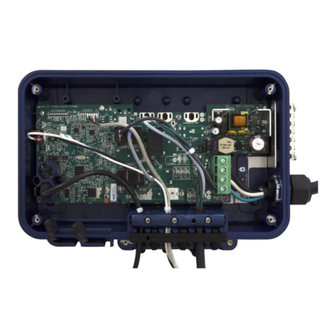
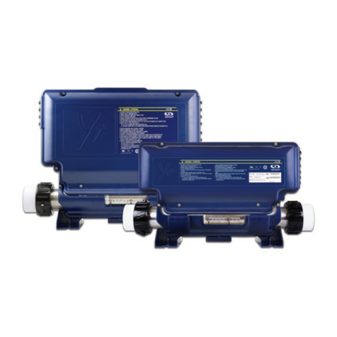
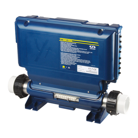
Gecko in.yj-2-V3 Technical manual

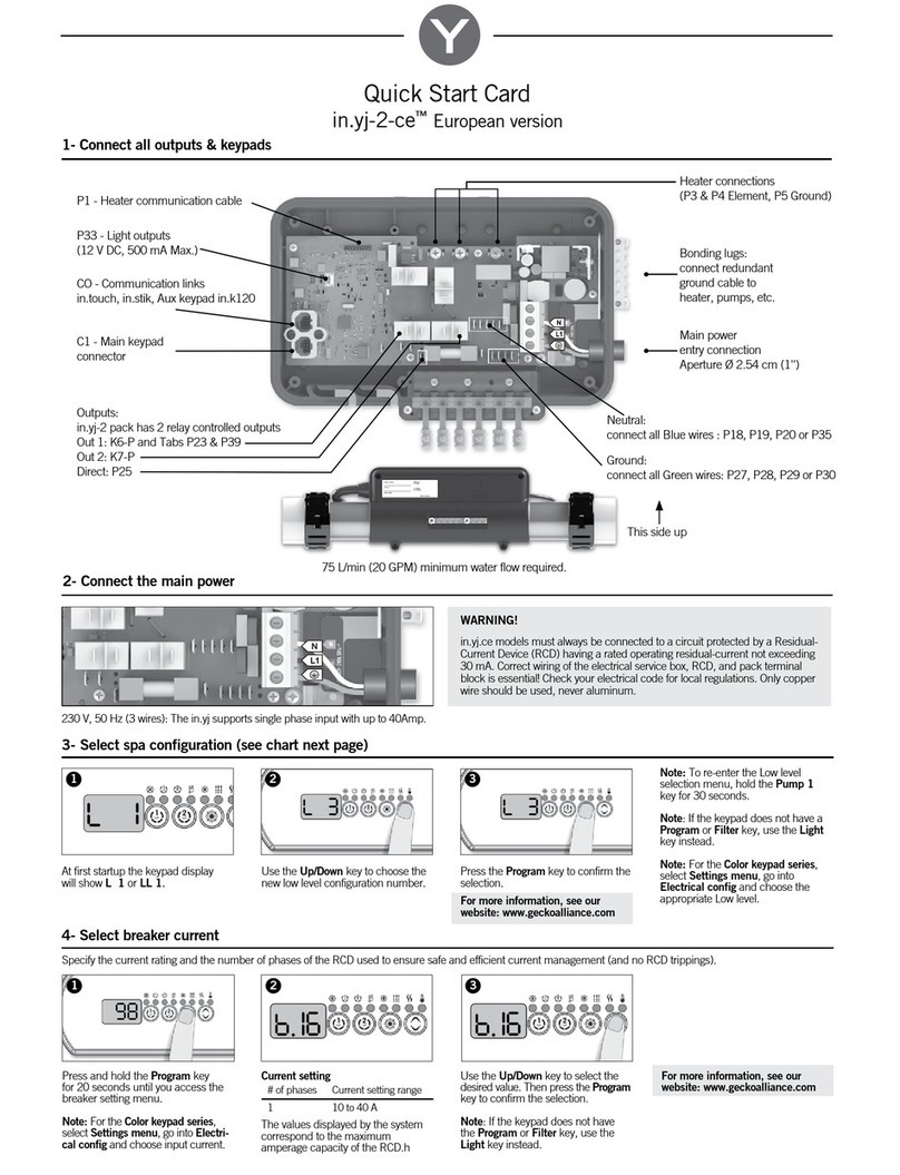
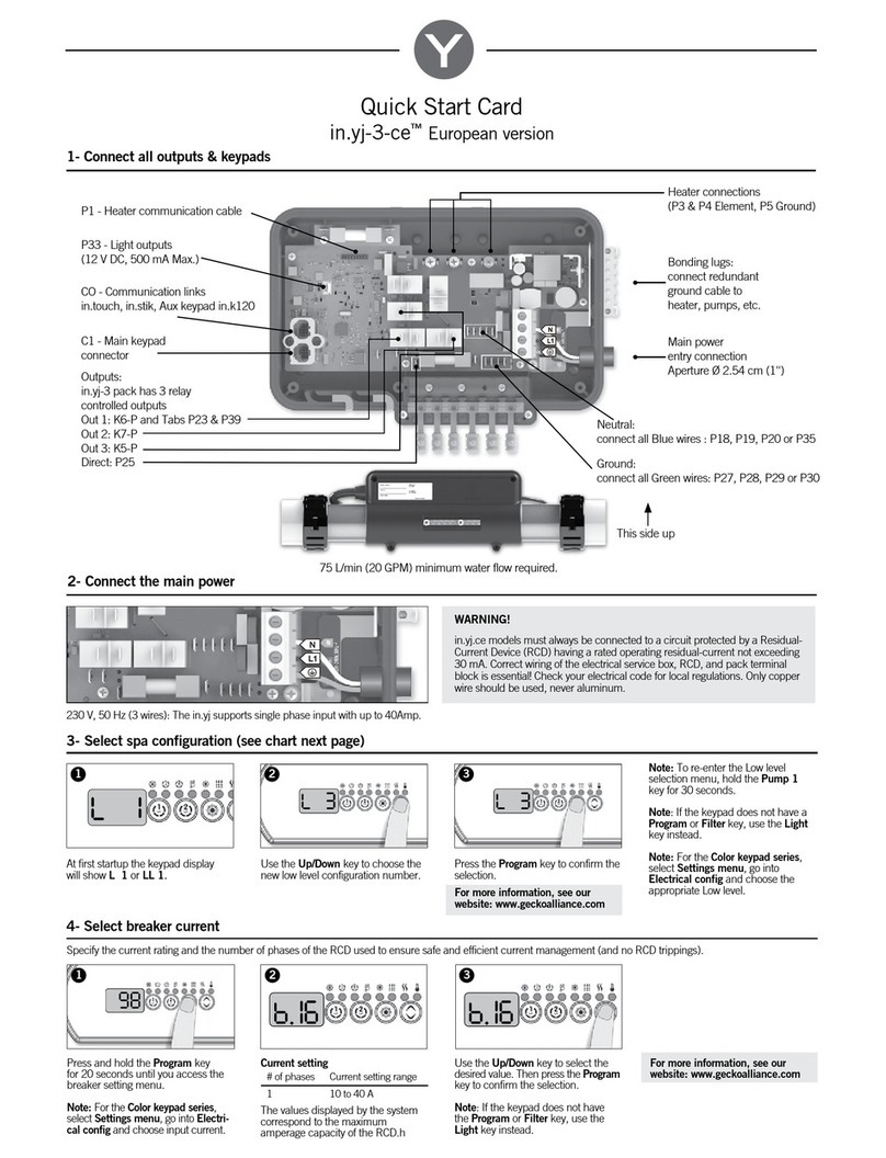
Quick Start Card
in.yj-2-V3™North American version
2- Connect the main power
1- Connect all outputs & keypads
3- Select spa configuration (see back page)
3
At first startup the keypad display
will show L 1 or LL 1.
Note: To re-enter the Low level
selection menu, hold the
Pump 1 key for 30 seconds.
Note: If the keypad does not have a
Program or Filter key, use the Light
key instead.
Note: For the Color keypad series,
select Settings menu, go into
Electrical config and choose the
appropriate Low level.
Use the Up/Down key to choose the
new Low level configuration number.
Press the Program key to confirm the
selection.
21
Heater connections
(P3 & P4 Element, P5 Ground)
P33 - Light outputs (12 V DC, 1 AMP)
P38 - in.lu.me
Main power entry connection
Aperture Ø 2.54 cm (1'')
Ground:
connect all Green wires: P27, P28, P29 or P30
C1 - Main keypad connector
P1 - Heater communication cable Bonding lugs:
connect redundant ground cable
to heater, pumps, etc.
68,1 L/min (18 GPM) minimum water flow required.
This side up
Outputs:
in.yj-2 pack has 2 relay controlled outputs
Out 1: K7-P
Out 2: K6-P
Direct: P25
240 V (4 wires)
Remove and discard brown wire and
insert each wire into the appropriate
socket of the main terminal block ac-
cording to the color code indicated on
the sticker. Use a flat screwdriver to
tighten the screws on the terminal.
Look at the pump and accessory voltage requirement and make sure to connect
each WHITE common wire to the correct tab on the board: Use any neutral tab for
120 V or use any LINE2 tab for 240 V
WARNING! All connections must be made by a qualified electrician in
accordance with the national electrical code and any state, provincial or local
electrical code in effect at the time of the installation. This product must always be
connected to circuit protected by a Ground Fault Circuit Interrupter (GFCI).
2.a- Electrical wiring 2.b- Pump & accessory voltage
Press and hold the Program key for
20 seconds until you access the
breaker setting menu.
Note: For the Color keypad series,
select Settings menu, go into Electri-
cal config and choose Input current.
4- Select breaker current
Breaker setting for GFCI used.
GFCI b
50 A 40 A
40 A 32 A
30 A 24 A
20 A 16 A
15 A 12 A Use the Up/Down key to select the
desired value. Then press the Program
key to confirm the selection.
Note: If the keypad does not have the
Program or Filter key, use the Light key
instead.
The values displayed by the system
correspond to 80% of the maximum
amperage capacity of the GFCI.
98
For more information, see our
website: www.geckoalliance.com
For more information, see our
website: www.geckoalliance.com
321
(10 to 20A is only to be use with
120V input)
Neutral: connect White wires from
120V pump / acc : P18, P19, P20, P21 or P35
Line 2: connect White wires from 240V
pump / acc : P14, P15, P16 or P37
120 V (3 wires)
DO NOT REMOVE THE BROWN WIRE.
Insert each wire into the appropriate
socket of the main terminal block
according to the color code indicated
on the sticker. Use a flat screwdriver to
tighten the screws on the terminal.
CO - Communication links
in.touch, in.stik, Aux keypad in.k120
Information between ( ) indicates which connector/tab to use. See drawing from Step 1 for connector position.
Configuration selection chart
Standard
config. # Pump 1 Pump 2 Circ. Pump (CP)
configuration
Ozone (O3)
configuration Filter cycle daily Heater
1
2SP
(K7-P, K6-P)
10A-3A
_ _ _
2 * 1 hour
with P1 Pump 1
2
1SP
(K7-P)
4A
_ _
During filter cycle, with P1
(K6-P)
2 * 1 hour
with P1 Pump 1
3
1SP
(K7-P)
4A
1SP
(K6-P)
8A
_ _
2 * 1 hour
with P1 Pump 1
4
1SP
(K7-P)
10A
_
During filter cycle
(K6-P)
1A
_
2 * 6 hour
with CP CP
5
2SP
(K7-P, K6-P)
10A-3A
_
Always on
(P-25)1
1A
_2 * day purge CP
6
1SP
(K7-P)
10A
1SP
(K6-P)
8A
Always on
(P-25)1
1A
_2 * day purge CP
7
1SP
(K7-P)
10A
_
Always on
(P-25)1
1A
Always on, with CP
(K6-P) 2 * day purge CP
Software #435, rev. 001
Note 1:Circulation pump is not controled via a relay and will run 24/7. Circulation pumps must provide at least 68,1 L/min (18 GPM) without creating kinetic heating of the water
(Gecko recommends using the Aqua-Flo Circ-Master - 1/15 HP).
For complete TechBook or more information, see our website: www.geckoalliance.com
9919-101599-A Rev. 01-2019 www.geckoalliance.com
© Groupe Gecko Alliance Inc., 2019
All trademarks or registered trademarks are the property of their respective owners.
Glossary
XInstalled
1SP High speed only
2SP High and low speed
10A, 10A-3A Output current: single speed (1SP) or dual speed High-Low (2SP)

Other Gecko Control System manuals

Gecko Y Series User manual

Gecko

Gecko Y Series User manual

Gecko Aeware Swim spa solution User manual

Gecko

Gecko Aeware Swim spa solution User manual

Gecko Y Series User manual

Gecko

Gecko Y Series User manual

Gecko in.yj-2 Technical manual

Gecko

Gecko in.yj-2 Technical manual

Gecko in.yj-3-ce Technical manual

Gecko

Gecko in.yj-3-ce Technical manual

Gecko in.yj-2 Technical manual

Gecko

Gecko in.yj-2 Technical manual

Gecko in.yj-2-CE Technical manual

Gecko

Gecko in.yj-2-CE Technical manual

Gecko in.xm2 Technical manual

Gecko

Gecko in.xm2 Technical manual

Gecko in.xm2 Technical manual

Gecko

Gecko in.xm2 Technical manual

Gecko in.yt-7-CE Technical manual

Gecko

Gecko in.yt-7-CE Technical manual

Popular Control System manuals by other brands

Radionics D2412 installation manual

Radionics

Radionics D2412 installation manual

Compool Cp3600 Installation & operating instructions

Compool

Compool Cp3600 Installation & operating instructions

Trane CCUN 205-211 user guide

Trane

Trane CCUN 205-211 user guide

Mitsubishi Electric CNC 700 Series Connection manual

Mitsubishi Electric

Mitsubishi Electric CNC 700 Series Connection manual

nxt BIA-nXt-Protect 1-22 Installation and operation manual

nxt

nxt BIA-nXt-Protect 1-22 Installation and operation manual

ooznest WorkBee CNC Assembly instructions

ooznest

ooznest WorkBee CNC Assembly instructions

Phason Supra Touch Series manual

Phason

Phason Supra Touch Series manual

Philips dynalite installation guide

Philips

Philips dynalite installation guide

Vibration Research VR8500 quick start guide

Vibration Research

Vibration Research VR8500 quick start guide

Daintree WWD2-4IW installation guide

Daintree

Daintree WWD2-4IW installation guide

Saab TankRadar G3 Service manual

Saab

Saab TankRadar G3 Service manual

Siemens RVW26.000B27 Basic documentation

Siemens

Siemens RVW26.000B27 Basic documentation

PEHA PHC MCC Installation and operating instructions

PEHA

PEHA PHC MCC Installation and operating instructions

Fagor 101 operating manual

Fagor

Fagor 101 operating manual

ABB ACS800-02 Hardware manual

ABB

ABB ACS800-02 Hardware manual

Mitsubishi Electric BAC-HD150 Instruction book

Mitsubishi Electric

Mitsubishi Electric BAC-HD150 Instruction book

EGi MILLENIUM user manual

EGi

EGi MILLENIUM user manual

LSC MANTRA LITE quick start guide

LSC

LSC MANTRA LITE quick start guide

manuals.online logo
manuals.online logoBrands
  • About & Mission
  • Contact us
  • Privacy Policy
  • Terms and Conditions

Copyright 2025 Manuals.Online. All Rights Reserved.