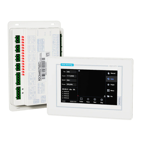
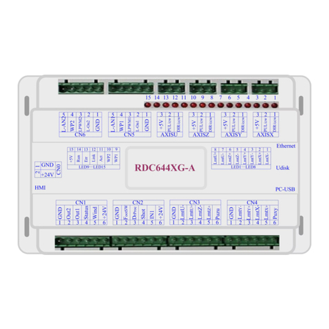
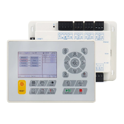
RuiDa RDC6563F User manual

RDC6563F Standalone Fiber Cutting Control System User Manual V2.0 I
SHENZHEN RUIDA TECHNOLOGY CO., LTD
RDC6563F
Standalone Fiber Cutting Control
System User Manual V2.0
Users should read this manual before using the controller.
This manual contents is the system operation manual
Read this manual carefully to ensure proper electrical connection
SHENZHEN RUIDA TECHNOLOGY CO., LTD
Address :301A.302B,Technology Building,NO.,1067 Nanhai
Avenue,Nanshan District,Shenzhen city,Guangdong
Province,P.R.China
Tel:0755--26066687
Fax:0755--26982287
E-mail:[email protected]
Website:www.rd-acs.com

RDC6563F Standalone Fiber Cutting Control System User Manual V2.0 1
SHENZHEN RUIDA TECHNOLOGY CO., LTD
Copyright Declaration
Shenzhen Ruida Technology Co., Ltd. (hereinafter referred to
as Ruida Technology) reserves all rights.
Ruida Technology has the patent copyright and intellectual property
rights of this product. It may not directly or indirectly copy, manufacture,
process and use this product and its related parts without the
authorization and permission of Ruida Technology. Otherwise, Ruida
Technology will pursue relevant legal responsibilities according to law.
Ruida Technology has the right to modify the products and product
specifications in this manual without prior notice, and has the right to
modify any documents attached to this product.
Users should read this manual carefully when using the products
described in this manual. Ruida Technology shall not be liable for any
direct, indirect, special, incidental or consequential loss or liability arising
from the use of this manual or the improper use of this product. Ruida
Technology does not assume the following direct or indirect liabilities or
losses.
Users use this manual or this product is improper
The user did not follow the relevant safety procedures
The loss caused by natural forces makes the machine dangerous
during working. The user has the responsible for designing effective error
handling and safety protection mechanisms in the machine. Ruida
Technology has no obligation or responsibility to be responsible for the
incidental or consequential damage.

RDC6563F Standalone Fiber Cutting Control System User Manual V2.0 2
SHENZHEN RUIDA TECHNOLOGY CO., LTD
Certification statement
CE Certification statement
This product has passed the CE (Community European) safety certification, and
has passed the corresponding conformity assessment procedures and the
manufacturer's declaration of conformity, in line with the relevant EU directives.
ROHS Certification statement
This product has passed the safety regulations of the Restriction of Hazardous
Substances, which is enacted by EU legislation, and complies with the relevant
environmental protection regulations of the European Union.
FCC Certification statement
This product has passed the US Federal Communications Commission safety
certification, in line with US electronic product safety regulations.

RDC6563F Standalone Fiber Cutting Control System User Manual V2.0 3
SHENZHEN RUIDA TECHNOLOGY CO., LTD
Safety information
Please make sure that the operation is correct and the method is safe when
using the system. Some signs or words will be used to remind you of dangerous
matters and some important information.
Important:
It indicates important information that needs attention during
using of the product. Please don't ignore this information, which
will provide effective operation assistance.
This mark indicates laser radiation and is generally applied to the
product that outputs the laser. Please be careful when using this
type of equipment, pay attention to safety.

RDC6563F Standalone Fiber Cutting Control System User Manual V2.0 4
SHENZHEN RUIDA TECHNOLOGY CO., LTD
Receiving, Unpacking, Inspection
The product has a plastic or metal casing to protect the exterior electrical
component from damage. The product is wrapped in a foam bag and packed in an
antistatic bag. If the package has any external damage, please check the goods and
notify the carrier of the damage situation in writing.
Important:
After receiving the products, please check whether the outer
packaging is in good condition, whether the product is complete
after unpacking, and whether the parts are in good condition. If
you find damage, please contact Ruida Technology immediately.
Keep the packaging materials and wiring accessories when unpacking. Please
be careful when disassembling the package. After unpacking the goods, please
check if the parts are complete. If you find that the parts are missing or the parts are
damaged, please contact Ruida Technology immediately. If you notice any obvious
damage to the device, do not install the device or commission the device.
RDC6563F standalone fiber cutting system delivery list is shown in the following:
(As the product is constantly updated, the accessories that may be received are
different from this list)
Component
Quantity
Description
RDC6563F mainboard
1
RDC6563F-HMI panel
1
DB9-3M
1
USB cable-2.0-black
1
USB Adapter cable AM/AF- 1M
1
USB Adapter cable -1M-black
1
Network cable -5M-blue
1
BWK301- Wireless handset
1
include:BWK301-
Wireless remote control,
BWK301R-wireless
receiver, 433MHz-2dB
helical antenna
LFS-AP02 Amplifier
1
15m Amplifier cable-black
1

RDC6563F Standalone Fiber Cutting Control System User Manual V2.0 5
SHENZHEN RUIDA TECHNOLOGY CO., LTD
Sensor cable -16cm- Silver white
1
U-disk-4G
1
Steel rail 350*35*7.5MM
1
Rail mount
2
3.81MM- Curved insertion -6P
socket-black
6
5.08MM- Curved insertion --3P socket -
black - With fixing screws
1
DB15- Welding wire-3
4
DB15-VGA shell
4
DB15 motor cable-2m
3
DB25 motor cable-2m
1

RDC6563F Standalone Fiber Cutting Control System User Manual V2.0 6
SHENZHEN RUIDA TECHNOLOGY CO., LTD
Contents
Chapter 1 Overview..................................................................................................................................... 9
1.1 Introduction to standalone fiber cutting control system....................................................... 10
1.1.1 Functional Description.......................................................................................................10
1.2 RDC6563F main technical parameters.................................................................................. 11
1.2.1 RDC6563F main technical parameters.......................................................................... 11
1.2.2 Z Axis following system technical parameters.............................................................. 11
1.3 Mainboard size chart................................................................................................................. 12
1.4 Panel size chart.......................................................................................................................... 14
1.5 Amplifier installation Dimensions.............................................................................................16
Chapter 2 Hardware Wiring Instruction.................................................................................................. 17
2.1 System wiring diagram.............................................................................................................. 18
2.2 Sensor Amplifier interface.........................................................................................................18
2.3 Main power input interface....................................................................................................... 18
2.4 HMI interface...............................................................................................................................19
2.5 PC-USB interface.......................................................................................................................19
2.6 U-disk interface...........................................................................................................................19
2.7 Ethernet interface.......................................................................................................................20
2.8 BWK interface............................................................................................................................. 20
2.9 X、Y、U、A axis motor interface............................................................................................20
2.10 Z axis motor interface................................................................................................................ 24
2.11 Limit switch interface................................................................................................................. 30
2.12 LASER interface......................................................................................................................... 31
2.13 AB switch interface.................................................................................................................... 33
2.14 Input IO........................................................................................................................................ 34
2.15 General Output IO......................................................................................................................35
2.16 Indicator Description.................................................................................................................. 37
Chapter 3 HMI Functions Introduction....................................................................................................39
3.1 Introduction..................................................................................................................................40
3.1.1 Overview..............................................................................................................................40
3.2 Button function introduction......................................................................................................40
3.3 Main interface function.............................................................................................................. 42
3.4 User parameters.........................................................................................................................44
3.5 Vendor parameters.................................................................................................................... 50
3.6 File................................................................................................................................................ 55
3.6.1 Memory file..........................................................................................................................55
3.6.2 Layer parameters............................................................................................................... 56
3.6.3 Memory Operation............................................................................................................. 57
3.6.4 U-disk files........................................................................................................................... 57
3.7 Menu.............................................................................................................................................58
3.7.1 Speed settings.................................................................................................................... 59
3.7.2 Power settings.................................................................................................................... 60
3.7.3 Language Settings............................................................................................................. 60

RDC6563F Standalone Fiber Cutting Control System User Manual V2.0 7
SHENZHEN RUIDA TECHNOLOGY CO., LTD
3.7.4 Screen Origin Settings...................................................................................................... 61
3.7.5 System Information............................................................................................................61
3.7.6 Multiple Anchor Point Settings......................................................................................... 62
3.7.7 Parameter Backup............................................................................................................. 64
3.7.8 Parameter Recovery..........................................................................................................64
3.7.9 Permission Settings........................................................................................................... 64
3.8 Functions..................................................................................................................................... 65
3.8.1 Axis reset............................................................................................................................. 65
3.8.2 Accessibility.........................................................................................................................66
3.8.3 Alarm Record...................................................................................................................... 67
3.8.4 Keyboard lock..................................................................................................................... 67
3.8.5 Diagnosis............................................................................................................................. 68
3.8.6 HMI Firmware Upgrade.....................................................................................................69
3.9 Password Management............................................................................................................ 70
3.9.1 Password input................................................................................................................... 70
3.9.2 Password Settings............................................................................................................. 71
Chapter 4 Follow System..........................................................................................................................72
4.1 Follow-up system function........................................................................................................ 74
4.1.1 Servo calibration.................................................................................................................74
4.1.2 Capacitor calibration..........................................................................................................74
4.1.3 Auto-tuning.......................................................................................................................... 76
Chapter 5 BWK Handheld Box................................................................................................................ 79
5.1 BWK Wireless Handheld Box Introduction............................................................................ 80
5.1.1 handheld box button function description...................................................................... 80
Chapter 6 System Test..............................................................................................................................83
6.1 X, Y axis motion test.................................................................................................................. 84
6.2 Z Axis following test................................................................................................................... 84
6.3 Laser test..................................................................................................................................... 85
6.4 Cutting test.................................................................................................................................. 85
Chapter 7 Alarm Message Description...................................................................................................90
7.1 Alarm Information Description..................................................................................................91
7.1.1 System error........................................................................................................................91
7.1.2 Upper and lower limit trigger............................................................................................ 91
7.1.3 X、Y、U、A Hard limit trigger......................................................................................... 91
7.1.4 Reset error...........................................................................................................................92
7.1.5 The capacitance value becomes smaller.......................................................................92
7.1.6 Collision alarm.................................................................................................................... 92
7.1.7 Air pressure alarm..............................................................................................................93
7.1.8 Large following error..........................................................................................................93
7.1.9 Encoder error...................................................................................................................... 93
7.1.10 X、Y、U、A Axis servo alarm......................................................................................... 93
7.1.11 Z Axis servo alarm..............................................................................................................93
7.1.12 Machine protection.............................................................................................................94
7.1.13 Following alarm.................................................................................................................. 94

RDC6563F Standalone Fiber Cutting Control System User Manual V2.0 8
SHENZHEN RUIDA TECHNOLOGY CO., LTD
7.1.14 Machine alarm.................................................................................................................... 94
7.1.15 Frame crossing...................................................................................................................95
7.1.16 Mainboard communication failed.....................................................................................95
7.1.17 No file................................................................................................................................... 95
Chapter 8 Device Connection............................................................................................................... 96
8.1 USB drive installation................................................................................................................ 97
8.1.1 USB Automatic installation............................................................................................... 97
8.2 USB Device connection............................................................................................................ 98
8.3 Ethernet device connection...................................................................................................... 99
8.3.1 Panel settings................................................................................................................... 100
Chapter 9 Appendix.............................................................................................................................. 102
9.1 Common Troubleshooting Methods......................................................................................103

RDC6563F Standalone Fiber Cutting Control System User Manual V2.0 9
SHENZHEN RUIDA TECHNOLOGY CO., LTD
Chapter 1 Overview
Main contents
RDC6563F system introduction
RDC6563F Technical parameter introduction
Product installation dimension drawing

RDC6563F Standalone Fiber Cutting Control System User Manual V2.0 10
SHENZHEN RUIDA TECHNOLOGY CO., LTD
1.1 Introduction to standalone fiber cutting control system
RDC6563F is a fiber cutting control system independently developed by Ruida Technology.
This control system has better hardware stability and better resistance to high voltage and
antistatic interference. The human-machine operating system based on LINUX has a more
friendly operation interface and more powerful functions. The controller includes more complete
and better motion control functions, large-capacity file storage, more compatible U disk driver,
multi-channel general/dedicated IO control, integrated dedicated time system to support
hardware encryption algorithm, and PC communication support. Ethernet communication and
USB communication are optional.
The Z-axis is an automatic height-adjusting system based on capacitive sensing technology.
It uses a high-performance amplifier and a professional anti-jamming design. The use of speed
closed-loop control greatly improves the performance of the height controller speed and
response speed, and achieves precise automatic height control. With the RDCutist software, you
can achieve the functions of leapfrog, flight cutting, short-distance without lifting.
1.1.1 Functional Description
Achieve high-speed motion and response speeds of servo motors or stepper
motors.
Support leapfrog, flight cutting, short-distance without lifting
Support automatic feeding, AB switching movement functions.
Supports multiple protection functions such as collision alarm, limit protection, and
servo alarm.
Capacitor parameter auto-calibration can be achieved to match any cutting head.
Support different lifting height and speed settings to facilitate different ways of
cutting
Supports a variety of punching methods such as segmental punching, progressive
punching, and pulse punching.
Optimized gas control, effective reduction of gas loss, 3-way gas control output.
Support remote control of wireless controller, USB, Ethernet.
The system comes with a time system for system encryption and installment
payment management.

RDC6563F Standalone Fiber Cutting Control System User Manual V2.0 11
SHENZHEN RUIDA TECHNOLOGY CO., LTD
1.2 RDC6563F main technical parameters
1.2.1 RDC6563F main technical parameters
Supports up to 6 axes of high speed motion, and with a maximum pulse frequency of
500 KHz.
Each axis supports positive and negative limits, servo alarm input detection and
protection.
Linear/Arc/B-spline interpolation accuracy +/- 0.5 pulses.
Supports small circle speed limit, power following functions.
15 general-purpose opto-isolated inputs compatible with 5V/12V/24V logic voltage.
15 general-purpose opto-isolated OC gate output, maximum 300mA drive capability
(with freewheeling protection), it can directly drive 24V/5V DC relay.
S-type acceleration and deceleration control and adaptive speed look-ahead
processing ensure smooth running.
Lasers can support a variety of laser types such as fiber optics and glass tubes.
Support 5V, 24V PWM / L_ON laser control signal output.
Support 5V, 10V analog voltage laser power control output.
1.2.2 Z Axis following system technical parameters
The dynamic following accuracy is less than 0.1mm.
The detection accuracy is less than 0.01mm.
Capacitance detection range is 0 to 9.9mm.
-10V ~ +10V servo drive analog voltage control output.
The maximum speed can reach 800mm/s, and the maximum acceleration can reach
10000mm/s^2.

RDC6563F Standalone Fiber Cutting Control System User Manual V2.0 12
SHENZHEN RUIDA TECHNOLOGY CO., LTD
1.3 Mainboard size chart
RDC6563FMainboard size is shown below:
unit:mm
Top view
Front view

RDC6563F Standalone Fiber Cutting Control System User Manual V2.0 13
SHENZHEN RUIDA TECHNOLOGY CO., LTD
Left view
Bottom view

RDC6563F Standalone Fiber Cutting Control System User Manual V2.0 14
SHENZHEN RUIDA TECHNOLOGY CO., LTD
1.4 Panel size chart
RDC6563F panel size is shown below:
unit:mm
Front view

RDC6563F Standalone Fiber Cutting Control System User Manual V2.0 15
SHENZHEN RUIDA TECHNOLOGY CO., LTD
Bottom view
Right view

RDC6563F Standalone Fiber Cutting Control System User Manual V2.0 16
SHENZHEN RUIDA TECHNOLOGY CO., LTD
1.5 Amplifier installation Dimensions
The amplifier size is shown below:
Unit:mm

RDC6563F Standalone Fiber Cutting Control System User Manual V2.0 17
SHENZHEN RUIDA TECHNOLOGY CO., LTD
Chapter 2 Hardware Wiring Instruction
Main contents:
System wiring diagram
Hardware interface description
Motor wiring instructions
Laser wiring instructions

RDC6563F Standalone Fiber Cutting Control System User Manual V2.0 18
SHENZHEN RUIDA TECHNOLOGY CO., LTD
2.1 System wiring diagram
The overall wiring diagram of the system as belowing:
2.2 Sensor Amplifier interface
Sensor is an amplifier connection interface ,this interface is connects one end of the
15-meter cable to the height sensor and the other connects to the amplifier.
When installing the amplifier, make sure that the outer casing of the amplifier and the outer
casing of the cutting head are reliably connected; Use a multimeter to measure the conduction
state. The cutting plate needs to be in effective contact with the machine body, and the
impedance between the two is less than 10 ohms, otherwise the detection effect of the capacitive
sensor will be affected.
Important:
Do not disassemble or cut the 15-meter amplifier cable.
Otherwise, the amplifier may be damaged or the signal may be
unstable.
2.3 Main power input interface
Main power input interface definition, as shown in the following table:

RDC6563F Standalone Fiber Cutting Control System User Manual V2.0 19
SHENZHEN RUIDA TECHNOLOGY CO., LTD
signal
definition
Description
+24V
+24V power input
controller+24V power input, Power supply
current output capability is greater than 3A
GND
GND
—
PG
External shield
Generally connected to the earth or the
shell
2.4 HMI interface
HMI is DB9 interface, the manufacturer's special shielded cable to connect mainboard and
HMI.
Important:
Do not use hot plug the DB9 terminal during to avoid damage to
internal components.
2.5 PC-USB interface
PC-USB is USB-BM port.It is the interface that the motherboard and PC access through
USB2.0.Connect PC from USB cable. If using USB to connect the controller, please set to USB
from RDCutist software. If you are the first time connect the controller in this PC, you should
install the USB driver, about USB driver Installation details. Please refer to the "Device
Connection" section for instructions.
2.6 U-disk interface
U-disk is USB-AM port,it is the port for mainboard access the U disk, it can copy standalone
files. The capacity of the U disk is generally less than 8G. Otherwise, the read and write speed
may be too slow or even the U disk may not be recognized.
Important:
Please pay attention to the USB interface on the panel and the
Udisk interface on the mainboard. The USB interface on the panel
is used for panel firmware upgrade. The U-disk interface on the
motherboard is used for copying standalone files.
Table of contents
Other RuiDa Control System manuals
Popular Control System manuals by other brands

GSI Group
GSI Group II Sweep Series owner's manual

Well Straler
Well Straler 3003EU user guide

Roger
Roger CPR32-SE v2.0 operating manual

iO HVAC Controls
iO HVAC Controls ZP6-ESP-PRO installation guide

MASTERZONE
MASTERZONE ZONEFIRST ZONE-ADDER MZA2 Installation and operating instructions

AgSense
AgSense Aqua Trac Pro Wiring Manual