manuals.online logo
Brands
  1. Home
  2. •
  3. Brands
  4. •
  5. Festo
  6. •
  7. Gateway
  8. •
  9. Festo CPX-IOT User manual

Festo CPX-IOT User manual

Translation of the original instructions
EtherNet/IP®, OPCUA®, PI PROFIBUS PROFINET®, SPEEDCON® are registered
trademarks of the respective trademark owners in certain countries.
1 Intended use
The module described in this document is intended for use in the industrial sector
as a gateway between industrial Ethernet networks and cloud applications, such
as, forexample, Festo Dashboard applications.
The module is intended for installation in machines or automation-technology
systems and may only be used only as follows:
– In perfect technical condition
– In its original condition, without unauthorised modifications, except for the
adaptations described in this document
– Within the limits of the product defined by the technical data.
Outside of industrial environments, e.g.in commercial and mixed-residential
areas, it may be necessary to take measures to suppress interference.
Information on commissioning and operating the gateway, e.g. to activate the
network connections "Cloud" and "Device" and to integrate them into the cloud
("Onboarding"):
è 6.3 Rotary switch operating mode
èFesto App World, www.festo.com/appworld
èFesto Dashboards, dashboards.festo.com
Information on the terminal CPX:
èSystem description of the terminal CPX (CPX-SYS), www.festo.com/pk
All available documents for the product èwww.festo.com/pk.
Note on licencing
This product uses open-source software, which is subject to "GNU General Public
License", Version2 and "GNU Lesser General Public License",
Version2.1,among others.
The licence conditions of the GPL, LGPL and the other open-source licences can be
viewed via the integrated web server of the product:
• Connect the gateway via the network connection "Device" with a PC or Note-
book.
• Calling up the web server:
èhttp://<IP-Adresse_des_Netzwerkanschlusses_"Device"/cgi-bin/system-
about.
2 Safety
– Before assembly or installation work:
Switch off the power supply and secure it against being switched on again.
– For the electrical power supply, use PELV circuits in accordance with
IEC 60204-1/EN 60204-1.
– Observe the handling specifications for electrostatically sensitive devices.
– Seal unused connections with cover caps to achieve the required degree of
protection.
– Use connection hardware with the required degree of protection.
– Observe specifications in the system description of the terminal CPX
(CPX-SYS).
– Commission only a completely mounted and wired module.
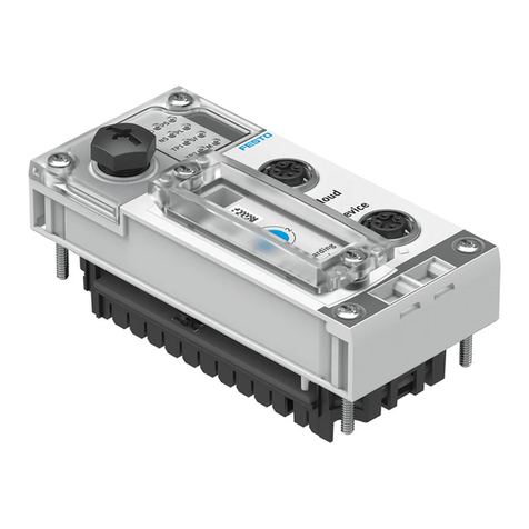
3 Connection and display components
1LED displays
2Network connection "Cloud"
3Network connection "Device"
4Rotary switch operating mode
5DIL switch
6Interface to the terminal CPX
without a network connection
è 8 Connection technology
Fig. 1 Connection and display components
3.1 Network connections
For connection to the Internet and the local industrial Ethernet network or direct
connection to the field devices, there are two industrial Ethernet interfaces on the
module, the network connections "Cloud" and "Device". Both connections have
Auto-Negotiation und Crossover detection (factory setting).
Cloud2) Device2)
Connection
1)
Pin
Signal3) Explanation Signal Explanation
1 TD+ Transmitted data + RD+ Received data +
2 RD+ Received data + TD+ Transmitted data +
3 TD– Transmitted data – RD– Received data –
4 RD– Received data – TD– Transmitted data –
Housing,
shielding con-
nected4)
FE,
Shield
Functional earth5) FE,
Shield
Functional earth5)
1) socket, M12, D-coded, 4-pin, SPEEDCON-compatible
2) Pin activation with deactivated crossover detection
3) TD = Transmit Data, RD = Receive Data, FE = Functional Earth
4) via RC link to functional earth
5) equipotential bonding èSystem description of the terminal CPX (CPX-SYS)
Tab. 1 Network connections
3.1.1 Fieldbus protocol and field devices
Via the network connection "Device", field devices can be directly connected with
an industrial Ethernet connection to the Gateway, e.g. bus node or controllers
(controller, PLC) with protocols such as, forexample, PROFINET, EtherNet/IP or
OPCUA.
Information on the supported field devices and controllers èFesto AppWorld,
www.festo.com/appworld.
3.1.2 Network security
NOTICE!
Unauthorised access to the device can cause damage or malfunctions.
When connecting the device to a network, protect the network from unauthorised
access.
Measures to protect the network include:
• Firewall
• Intrusion Prevention System (IPS)
• Network segmentation
• Virtual LAN (VLAN)
• Virtual Private Network (VPN)
• Security at physical access level (Port Security)
An access password only protects against unintentional modification.
For additional information èGuidelines and standards for security in information
technology, e.g. IEC62443, ISO/IEC27001.
When connecting the gateway, configure the firewall setting for the network con-
nection "Cloud" as follows:
– Outgoing connections: release for port 443 (HTTPS)
– Incoming connections: no port release
For further information on the required measures in terms of network security,
enter èwww.festo.com/sp: "CPX-IOT", filter according to Application Note .
8108871
CPX-IOT
Gateway
8108871
2019-04a
[8108873]
Instructions| Operating
Festo AG & Co. KG
Ruiter Straße 82
73734 Esslingen
Germany
+49 711 347-0
www.festo.com
3.2 LED displays
Network-specific LED displays Gateway-specific LED displays
Cloud
(blue)
Network status "Cloud" PS
(green)1)
Status of operating voltage -
supply
(Power System)
NS
(red/green)
Network status "Device"2) PL Reserved
TP1
(green)
Connection status "Cloud"
("Link/Traffic")
SF
(red)1)
System error
(System Failure)
TP2
(green)
Connection status "Device"
("Link/Traffic")2)
M
(yellow)
Module status "Onboarding"
1) General information on the LEDs PS and SF èSystem description of the terminal CPX (CPX-SYS)
2) Module positioning: LEDs PS, PL and NS flash at the same rate.
Tab. 2 LED displays
Normal operating status
Behaviour of the LED displays in a normal operating status:
– PS and NS illuminated green
– Cloud illuminated blue
– TP1 and/or TP2 illuminated or flashing green
– PL, SF and M are not illuminated
3.2.1 Network status "Cloud"
LED status Meaning Error handling
Illumin-
ated blue
Normal operating status:
Network connection to the cloud
("Link") created
–
Flashes
blue 1x
Creation or new creation of a con-
nection to the cloud
–
Flashes
blue 2x
Network error – Check the configuration, e.g.
DHCP address assignment,
static IP address
Off
No connection to the cloud – Check network connection
Tab. 3 Network status "Cloud" (LED with cloud symbol)
3.2.2 Network status "Device" (Network Status)
LED status Meaning Error handling
Illumin-
ated
green
Normal operating status:
The gateway is connected with field
devices ("Devices").
–
Flashes
green
No connection to field devices
("Devices"):
The gateway is online and has an IP
address, but is not yet connected
with field devices.
– Check configuration
– Check module status
– Restart module ("Reboot")
– Repeat "Onboarding"
Illumin-
ated red
Communication with the field
devices("Devices") has failed:
Non-permitted network configura-
tion, e.g. already used IP address.
– Check configuration, e.g.
DHCP address assignment,
static IP address
Flashes
red
Communication with field devices
has failed:
Network connection disturbed, z.B.
connecting cable interrupted.
– Check device connection
Off
The gateway is offline. – Check network connection
Tab. 4 Network status "Device" (Network Status, LED NS)
3.2.3 Module status "Onboarding"
LED status Meaning Error handling
Off
Normal operating status:
Onboarding completed.
The gateway has been successfully
integrated into the cloud applica-
tion.
The gateway is in the operating
mode "Off", "Read only" or
"Read/Write"
è 6.3 Rotary switch operating
mode.
–
Flashes
yellow 1x
Gateway Onboarding active:
The gateway is in operating mode
"Onboarding".
The gateway is integrated into the
cloud application.
–
Flashes 2x
yellow
The gateway is in operating mode
"Onboarding".
The gateway has been successfully
integrated into the cloud applica-
tion.
– Select operating mode
"Read only" or "Read/Write"
è 6.3 Rotary switch operating
mode
Flashes 3x
yellow
Devices Onboarding active.
The gateway performs a network
scan: supported devices
("Devices") are integrated into the
cloud application.
The gateway is in operating mode
"Read/Write".
–
Illumin-
ated yel-
low
The gateway is not yet integrated
into the cloud application.
The gateway is in the operating
mode "Off", "Read only" or
"Read/Write"
è 6.3 Rotary switch operating
mode.
– Perform Onboarding
Tab. 5 Module status "Onboarding" (LED M)
3.2.4 Connection status "Cloud"
LED status Meaning Error handling
Illumin-
ated
green
Normal operating status:
Network connection to the cloud
established
–
Flashes
green
Data traffic ("Traffic")1) –
Off
No network connection – Check network connection
1) Flashing frequency is dependent on the traffic.
Tab. 6 Connection status "Cloud" (Link/Traffic, LED TP1)
3.2.5 Connection status "Device"
LED status Meaning Error handling
Illumin-
ated
green
Normal operating status:
Network connection ("Link") to the
field devices ("Devices") estab-
lished
–
Flashes
green
Data traffic ("Traffic")1) –
Off
No network connection – Check network connection
1) Flashing frequency is dependent on the traffic.
Tab. 7 Connection status "Device" ("Link/Traffic", LED TP2)
3.2.6 Status of operating voltage supply (Power System)
LED status Meaning Error handling1)
Illumin-
ated
green
Normal operating status:
Operating voltage applied.
–
Flashes
green
Undervoltage:
Operating voltage outside the toler-
ance range.
– Rectify undervoltage.
Off
Operating voltage is not present – Check operating voltage sup-
ply
1) General information on LEDPS èSystem description of terminalCPX (CPX-SYS)
Tab. 8 Status of operating voltage supply (Power System, LED PS)
3.2.7 System error (System Failure)
LED
(red)
Process
1)
Meaning Error handling2)
Off
Normal operating status:
No error.
–
Flashes
red 1x
Simple error / information
(error class 1)3)
Flashes
red 2x
Error
(error class 2)4)
Flashes
red 3x
Serious error, internal error, e.g.
hardware error
(error class 3)5)
– Error handling
èFesto App World,
www.festo.com/appworld.
1) The LED SF flashes if an error occurs and is dependent on the error class.
2) General information on LEDSF èSystem description of the terminalCPX (CPX-SYS)
3) Error class1 (minor error): 1xflash, pause
4) Error class2 (error): 2xflashes, pause
5) Error class3 (serious error): 3xflashes, pause
Tab. 9 System error (System Failure, LED SF)
4 Assembly and disassembly
The module must be inserted into an interlinking block for the terminal CPX
èwww.festo.com/catalogue:
– Version 1:
Gateway in an interlinking block with system supply, e.g.CPX-GE-EV-S-...,
between two end plates
– Version 2:
Gateway in an interlinking block without supply, between two end plates with
system supply, e.g.CPX-EPL-EV-S-...
Information on power supply è 5 Power supply.
1Gateway CPX-IOT
2Screw
3Interlinking block
(with system supply)
Fig. 2 Assembly and disassembly
4.1 Assembly
NOTICE!
Material damage due to incorrect mounting.
Select screws that are suitable for the material of the interlinking block:
• Polymer: thread-grooving screws
• Metal: screws with metric thread
When ordering an individual module, all the screws required are enclosed.
1. Switch off the power supply and secure it against being switched on again.
2. Check seal and seal surfaces. Replace damaged parts.
3. Push the module carefully and without tilting into the interlinking block up to
the stop.
4. Turn the screws into the existing thread.
5. Tighten the screws in diagonally opposite sequence.
Tightening torque:1Nm ±10%.
4.2 Disassembly
1. Switch off the power supply and secure it against being switched on again.
2. Unscrew the screws.
3. Pull the module without tilting out of the interlinking block.
5 Power supply
The operating and load voltage supply is fed in via interlinking blocks or end
plates with system supply.
Information on power supply:
èSystem description of the terminal CPX (CPX-SYS)
èPin allocation power supply connection (CPX-PIN-BEL)
WARNING!
Risk of injury due to electric shock.
• For the electric power supply, use PELV circuits that guarantee a reliable elec-
tric disconnection from the mains network.
• Observe IEC 60204-1/EN 60204-1.
• Connect all circuits for the operating and load voltage supply.
6 Switching elements
1DIL switch 1
2DIL switch 2
3Rotary switch operating mode
Fig. 3 Switching elements
6.1 DIL switch 1
Switching position Function
DIL 1.1: Off
(factory setting)
Reserved
DIL 1.1: On Reserved
Tab. 10 DIL switch 1.1
Switching position Function
DIL 1.2: Off
(factory setting)
Reserved
DIL 1.2: On Reserved
Tab. 11 DIL switch 1.2
6.2 DIL switch 2
Switching position Function
DIL 2.1: Off
(factory setting)
Reserved
DIL 2.1: On è 10 Reset to factory setting ("FactoryReset")
Tab. 12 DIL switch 2.1
Switching position Function
DIL 2.2: Off
(factory setting)
Reserved
DIL 2.2: On è 10 Reset to factory setting ("FactoryReset")
Tab. 13 DIL switch 2.2
6.3 Rotary switch operating mode
Switching position Operating mode/function
0: Off – Network connection "Cloud" deactivated (switch-off of inter-
face)
– No communication with the cloud
1: Onboarding – Network connection "Cloud" activated
– Gateway for integration into the cloud ("Onboarding") ready
2: Readonly – Gateway sends process data of the configured field devices to
the cloud
– Manual adding of field devices enabled
– Automatic adding of field devices via the Auto-Scan function
blocked
– Removal of field devices and removal of the gateway from the
cloud ("Offboarding") blocked
– Receipt of data, e.g. parameters, from the cloud disabled
– Parameters of connected devices cannot be changed
3: Read/Write – Gateway sends process data of the configured field devices to
the cloud
– Manual adding of field devices enabled
– Automatic adding of field devices via the Auto-Scan function
enabled
– Removal of field devices and removal of the gateway from the
cloud ("Offboarding") enabled
– Receipt of data, e.g. parameters, from the cloud enabled
– Parameters of connected devices can be changed
Tab. 14 Rotary switch operating mode
7 Ensuring the degree of protection
NOTICE!
Short circuit as a result of ingress of liquids or foreign matter.
Malfunction or damage to the electronics.
• Use connection devices (connecting cables, plugs, adapters) with the
required degree of protection.
• Use cover caps to seal unused connections.
• Mount the DIL switch cover:
– Check the seal.
– Place cover and press it on.
– Tighten screws.
Tightening torque: maximum0.4Nm.
8 Connection technology
Using the M12 socket 6 (è Fig.1), a terminal CPX can be directly connected with
the gateway without a network connection, i.e. without an industrial Ethernet
connection.
Connection Connecting hardware Cover cap
Network connection "Cloud"1)
Network connection "Device"1)
Plug NECU-M-S-D12G4-C2-ET
Interface to terminal CPX
without a network connection2)
Connecting cable
NEBC-M12G5-S-1,5-N-M12G5
ISK-M12
1) socket, M12, D-coded, 4-pin, SPEEDCON-compatible
2) socket, M12, A-coded, 5-pin
Tab. 15 Connection technology
9 Parameterisation
The gateway can be parameterised via the FestoField Device Tool (FFT).
Alternatively, the integrated web server of the gateway can be used via the net-
work connection "Device" for the parameterisation, e.g. for setting the IP
addresses of the network connections:
Connect the gateway via the network connection "Device" with a PC or Notebook.
Calling up the web server:
èhttp://<IP-Adresse_des_Netzwerkanschlusses_"Device"> (see IP configuration
(factory settings) è 13 Technical data)
Logging in:
èUser name: admin
èPassword (factory setting): CPX-IoT Product Key on the type plate, e.g.
3S7PMM2M93V
10 Reset to factory setting ("FactoryReset")
1. Set rotary switch to "Off".
2. Switch off the power supply.
3. Set DIL switch 2.1 and 2.2 to "On".
4. Switch on the power supply.
ÄLEDM flashes quickly for a few seconds.
– Do not switch off the power supply
– Do not actuate the DIL switch
5. If the LEDM has stopped flashing:
Set DIL switch 2.1 and 2.2 to "Off".
ÄThe gateway has returned to the factory setting.
11 Firmware update
A firmware update is possible via the Festo Field Device Tool (FFT)
èwww.festo.com/sp.
12 Module replacement
After replacing a gateway, integration into the cloud („Onboarding“) must be car-
ried out again èFesto App World, www.festo.com/appworld.
13 Technical data
Property Specification/value
General technical data èSystem description of the
terminal CPX (CPX-SYS)
Power supply
Operating power supply UEL/SEN [VDC] 24 ±25%
Intrinsic current consumption at nominal operat-
ing voltage 24V from operating voltage supply
UEL/SEN
[mA] Typically 80
(internal electronics)
Mains buffering time [ms] 10
Separation of network interface from operating
voltage supply UEL/SEN
Galvanic
Protection against electric shock1) Through the use of PELV circuits
Degree of protection by housing2)3),
With power supply connection
– Via interlinking block IP65/IP67
– Via end plate IP20
Connection technology
Network connections 2 × sockets, M12, D-coded, 4-pin,
SPEEDCON-compatible
Interface to terminal CPX
without a network connection
1 × socket, M12, A-coded, 5-pin
Network-specific characteristics
Cloud DHCP IP configuration (factory settings)
Device IP address: 192.168.0.1
Subnet mask: 255.255.255.0
Encryption of data transmission to the Cloud HTTPS
Transmission technology Industrial Ethernet,
Switched Fast Ethernet
Specification IEEE 802.3u (100Base-TX)
Transmission rate [Mbit/s] 10/100 (full duplex/half duplex)
Crossover detection Auto-MDI/MDI-X
Number of devices (network connection
"Device")
Maximum 104)
Cable specification
Cable type Ethernet twisted pair cable, shiel-
ded (Shielded Twisted Pair, STP)
Transmission class (Link Class) Category Cat 5
Cable diameter5) [mm] 6…8
Wire cross section6) [mm2] 0.14…0.75
Cable length [m] Maximum 100
1) protection against direct and indirect contact in accordance with IEC60204-1/EN60204-1
2) Degree of protection in accordance with IEC60529, module completely assembled, plug connector in the
plugged-in status or provided with cover cap
3) Connected products may only fulfil a lower degree of protection.
4) More devices can be operated depending on the application.
5) when using the plug NECU-M-S-D12G4-C2-ET
6) 22AWG required for max. connection length between network participants (end-to-end link)
Tab. 16 Technical data
14 Specified standards
Version
IEC 60529:2001-02 IEEE 802.3:2014-00
Tab. 17 Specified standards

Other Festo Gateway manuals

Festo CESA-GW-AS-PB User manual

Festo

Festo CESA-GW-AS-PB User manual

Festo CESA-GW-AS-CO User manual

Festo

Festo CESA-GW-AS-CO User manual

Festo CPX-IOT User manual

Festo

Festo CPX-IOT User manual

Popular Gateway manuals by other brands

LevelOne AMG-2102 user manual

LevelOne

LevelOne AMG-2102 user manual

RTA 460ETCBM-N700 Product user guide

RTA

RTA 460ETCBM-N700 Product user guide

Baudcom BD-E1-SIP user manual

Baudcom

Baudcom BD-E1-SIP user manual

L&S SMART GATEWAY Technical data

L&S

L&S SMART GATEWAY Technical data

ZyXEL Communications P-660H-T1 v3s user guide

ZyXEL Communications

ZyXEL Communications P-660H-T1 v3s user guide

RTA 460AUSB-N70U Product user guide

RTA

RTA 460AUSB-N70U Product user guide

FIBARO YH-001 quick start guide

FIBARO

FIBARO YH-001 quick start guide

Daikin intelligent Touch Manager BACnet DCM014A51 Quick user guide

Daikin

Daikin intelligent Touch Manager BACnet DCM014A51 Quick user guide

RTA 460ESPBS-N70PB Product user guide

RTA

RTA 460ESPBS-N70PB Product user guide

Hypercom ATMConnect C5100 installation guide

Hypercom

Hypercom ATMConnect C5100 installation guide

MTX MTX-GATEWAY user guide

MTX

MTX MTX-GATEWAY user guide

3Com V6100 User	guide	guide

3Com

3Com V6100 User guide guide

Portech MV-374 user manual

Portech

Portech MV-374 user manual

Advantech EKI-136-MB-BE Series user manual

Advantech

Advantech EKI-136-MB-BE Series user manual

DAQ IoG user manual

DAQ

DAQ IoG user manual

Baudcom BD-FE1-IP-G user manual

Baudcom

Baudcom BD-FE1-IP-G user manual

LG BECON HVAC BACnet PQNFB17C1 Installation and user manual

LG

LG BECON HVAC BACnet PQNFB17C1 Installation and user manual

H3C MSR3610-X1 Installation quick guide

H3C

H3C MSR3610-X1 Installation quick guide

manuals.online logo
manuals.online logoBrands
  • About & Mission
  • Contact us
  • Privacy Policy
  • Terms and Conditions

Copyright 2025 Manuals.Online. All Rights Reserved.