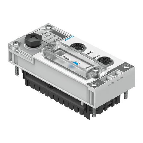
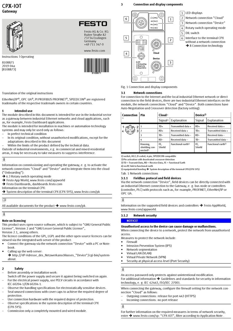
Festo CESA-GW-AS-CO User manual

Description
AS-i Gateway
English
Gateway AS-i - CANopen
CESA-GW-AS-CO
749964
1002NH


Weitergabe sowie Vervielfältigung dieses Doku-
ments, Verwertung und Mitteilung seines Inhalts
sind verboten, soweit nicht ausdrücklich gestattet.
Zuwiderhandlungen verpflichten zu Schadenersatz.
Alle Rechte sind für den Fall der Patent-, Gebrauchs-
muster- oder Geschmacks- mustereintragung vorbe-
halten.
The reproduction, distribution and utilization of this
document as well as the comunication of its contents
to others without express authorization is prohibited.
Offenders will be held liable for the payment of dam-
ages. All rights reserved in the event of the grant of a
patent, utility module or design.
Sin nuestra expresa autorización, queda terminante-
mente prohibida la reproducción total o parcial de
este documento, así como su uso indebido y/o ex-
hibición o comunicación a terceros. De los infractores
se exigirá el correspondiente resarcimiento de daños
y perjuicios. Quedan reservados todos los derechos
inherentes, en especial los de patentes, de modelos
registrados y estéticos.
Toute communication ou reproduction de ce docu-
ment, sous quelque forme que ce soit, et toute ex-
ploitation ou communication de son contenu sont in-
terdites, sauf autorisation écrite expresse. Tout
manquement à cette règle est illicite et expose son
auteur au versement de dommages et intérêts. Tous
droits réservés pour le cas de la délivrance d'un bre-
vet, d'un modèle d'utilité ou d'un modèle de présen-
tation.
È vietato consegnare a terzi o riprodurre questo docu-
mento, utilizzarne il contenuto o renderlo comunque
noto a terzi senza esplicita autorizzazione. Ogni in-
frazione comporta il riscarimento dei danni subiti.
Sono riservati tutti i diritti derivanti dalla conces-
sione di brevetti per invenzioni industriali di utilità o
di brevetti per modelli ornamentali.
Detta dokument får inte utan vårt tillstånd utlämnas
till obehöriga eller kopieras, ej heller får dess inne-
håll delges obehöriga eller utnyttjas. Överträdelse
medför skade- ståndskrav. Alla rättigheter förbe-
hålls, särskilt rätten att inlämna patent-, bruksmön-
ster- eller mönsteransökningar.
Copyright:
© Festo AG & Co. KG,
Postfach
D-73726 Esslingen
Phone:
+49 / 711 / 347-0
Fax:
+49 / 711 / 347-2144
e-mail:
service_internati[email protected]
Internet:
http://www.festo.com
Original: de
Version: 1002NH


CESA-GW-AS-CO Description 5
Table of contents
AS-i 3.0 CANopen Gateway in Stainless Steel
1 Symbol catalog ................................................................................... 10
1.1 Abbreviations ................................................................................................. 10
2 General ................................................................................................ 11
2.1 Product information....................................................................................... 11
2.2 Technical data ................................................................................................ 11
2.3 AS-i specification 3.0..................................................................................... 11
3 Safety ................................................................................................... 12
3.1 Intended use................................................................................................... 12
3.2 General safety information ........................................................................... 12
3.3 Disposal .......................................................................................................... 12
4 Installation........................................................................................... 13
4.1 Dimensions..................................................................................................... 13
4.2 Connections ................................................................................................... 13
4.3 Installing in the control cabinet.................................................................... 13
4.4 Removing........................................................................................................ 14
4.5 Electrical Connection .................................................................................... 14
4.6 Startup ............................................................................................................ 15
4.6.1 Switching to advanced display mode ......................................................................... 15
4.7 Setting the baud rate ..................................................................................... 15
4.8 Setting the NODE ID ...................................................................................... 16
4.8.1 Connecting AS-i Slaves................................................................................................ 16
4.9 Error tracing ................................................................................................... 17
4.9.1 Faulty slaves.................................................................................................................. 17
4.9.2 Error display (last error) ............................................................................................... 17
4.10 Quick setup .................................................................................................... 18
4.11 Addressing ..................................................................................................... 19
4.11.1 Program slave 0 to address 4 ...................................................................................... 19
5 Electrical connection ......................................................................... 20
5.1 Overview of terminals, indicators and operating elements ....................... 20

CESA-GW-AS-CO Description 6
5.1.1 CESA-GW-AS-CO ..........................................................................................................20
5.2 AS-i bus connection....................................................................................... 21
5.3 Information about the device types.............................................................. 21
5.4 AS-i and power supply terminal assignments.............................................21
5.4.1 Electrical connection CESA-GW-AS-CO ................................................................... 22
5.5 CANopen interface ........................................................................................ 23
5.6 Diagnostics interface ..................................................................................... 23
5.6.1 Diagnostics port RS 232 ............................................................................................... 23
5.7 Indicators and operating elements...............................................................24
5.7.1 LED indicators – master ............................................................................................... 24
5.7.1.1 CANopen LED "ser.active" flashing sample ................................................................. 25
5.7.2 Buttons ........................................................................................................................... 26
6 Operation in advanced display mode............................................... 27
6.1 Overview .........................................................................................................27
6.2 Navigating through the advanced display mode ........................................29
6.3 CANOPEN (main menu) ................................................................................. 30
6.3.1 NODE ID (CANopen NODE ID) ......................................................................................30
6.3.2 BAUDRATE ....................................................................................................................30
6.3.3 STATUS ..........................................................................................................................31
6.4 AS-I CONTROL (option) ................................................................................. 31
6.4.1 CONTROL INFO .............................................................................................................32
6.4.2 CONTROL RUN .............................................................................................................. 32
6.4.3 CONTROL FLAGS (control program flag memory) .................................................... 33
6.5 QUICK SETUP................................................................................................. 33
6.6 SLAVE ADR TOOL.......................................................................................... 34
6.7 SLAVE TEST TOOL ........................................................................................35
6.8 SETUP (configuration of an AS-i network) .................................................. 37
6.8.1 AS-I SLAVE ADR. (set/change slave address)............................................................37
6.8.2 FORCE OFFLINE (Switch AS-i Master to offline operation) ...................................... 38
6.8.3 OPERATION MODE ....................................................................................................... 38
6.8.4 STORE ACTUAL (store currently detected configuration) ........................................ 38
6.8.5 PERMANENT PARA (permanent parameters) ............................................................ 39
6.8.6 PERMANENT CONFIG (permanent configuration data)............................................. 40
6.8.7 AS-I ADDRESS (AS-i address assistant) ..................................................................... 40
6.8.8 LOS (list of offline slaves) ............................................................................................41
6.8.9 AUTO ADDR (enable automatic address) ................................................................... 41
6.8.10 FACTORY RESET (factory default settings) ............................................................... 42
6.9 IO + PARAM.TEST .......................................................................................... 42
6.9.1 BINARY INPUTS.............................................................................................................43
6.9.2 BINARY OUTPUTS.........................................................................................................43
6.9.3 ANALOG INPUTS........................................................................................................... 43
6.9.4 ANALOG OUTPUTS....................................................................................................... 44
6.9.5 PARAMETER..................................................................................................................45
6.10 DIAGNOSIS .....................................................................................................45
6.10.1 FLAGS ............................................................................................................................ 46
6.10.2 ACTUAL CONFIG (actual slave configuration) ........................................................... 47
6.10.3 LPF (List of Peripheral Faults) ..................................................................................... 48

CESA-GW-AS-CO Description 7
6.10.4 AS-I MASTER (info)....................................................................................................... 49
6.11 ADV. DIAGNOSIS (advanced diagnostics) .................................................. 49
6.11.1 LCS (History of the slaves which have triggered a configuration error) ................. 50
6.11.2 FAULT DETECTOR........................................................................................................ 50
6.12 AS-I SAFETY................................................................................................... 51
6.12.1 SAFETY SLAVES (safety oriented slaves).................................................................. 51
6.12.2 SAFETY MONITOR ........................................................................................................ 52
6.12.3 SAFETY SUBST VAL (Substitute values for input data from safe slaves) .............. 53
6.12.4 Language (menu language) ......................................................................................... 53
6.13 DISPLAY CONTRAST (set display contrast) ............................................... 53
7 Operation as CANopen Node ............................................................ 55
7.1 CANopen parameter communication........................................................... 56
7.1.1 Object directory............................................................................................................. 56
7.2 Fade-in/Fade-out Safety Slaves .................................................................... 58
7.3 Process Data Communication ...................................................................... 58
7.3.1 Mapping AS-i Data in CANopen PDOs ........................................................................ 58
7.3.1.1 RPDOs ......................................................................................................................... 60
7.3.1.2 TPDOs ......................................................................................................................... 61
7.3.2 LSS (Layer Setting Services) ....................................................................................... 61
7.3.3 Compatibility to AS-i 2.1 CANopen Gateway.............................................................. 61
8 CANopen Telegrams .......................................................................... 63
8.1 Representation of a CAN message .............................................................. 63
8.2 Default identifier distribution........................................................................ 64
8.2.1 Simplified Boot-up According to CANopen (NMT=0, DBT=0)................................... 65
8.2.2 Examples for data exchange........................................................................................ 68
9 Advanced Diagnostics for AS-i Masters ..........................................70
9.1 List of corrupted AS-i Slaves (LCS) ............................................................. 70
9.2 Protocol analysis: Counters for corrupted data telegrams ....................... 70
9.3 Offline Phase for Configuration Errors........................................................ 71
9.4 Functions of the AS-i Fault Detector............................................................ 71
9.4.1 Duplicate address detection ........................................................................................ 71
9.4.2 Earth/Ground Fault Detector........................................................................................ 72
9.4.3 Noise Detector............................................................................................................... 72
9.4.4 Over-voltage Detector................................................................................................... 72

CESA-GW-AS-CO Description 8
10 System startup using AS-i Control Tools ........................................ 73
11 Codes indicated by the display ........................................................ 76
12 Glossary.............................................................................................. 78
13 Reference List .................................................................................... 83
13.1 Manual: “AS-i 3.0 Command Interface“ ....................................................... 83

CESA-GW-AS-CO Description 9
Conformity Statement
The AS-i/CANopen Gateways have been developed and produced in
accordance with the applicable european standards and directives. The
conformity statement according to the EC EMC-, low voltage, and -
maschinery directive can be sent to by request.
Additional information can be found in the Festo basic catalogue or in the
online catalogue in internet.
Subject to technical modifications.

CESA-GW-AS-CO Description 10
1. Symbol catalog
1.1 Abbreviations
Information!
This symbol indicates important information.
Attention!
This symbol warns of a potential failure. Non-compliance may lead to interruptions of
the device, the connected peripheral systems, or plant, potentially leading to total mal-
functioning.
Warning!
This symbol warns of an imminent danger. Non-compliance may lead to personal inju-
ries that could be fatal or result in material damages and destruction.
Information!
Additional information can be found in section <Glossary>.

CESA-GW-AS-CO Description 11
2. General
2.1 Product information
This system manual applies to the following Festo equipment:
The AS-i/CANopen Gateways serve to connect AS-i systems to the superordi-
nate CANopen. The gateways act as a master for AS-i and as a slave on
CANopen.
2.2 Technical data
The technical data are placed in the data sheet. Please view the current version
on the web page: http://www.festo.com
2.3 AS-i specification 3.0
The AS-i 3.0 gateways already fulfil the AS-i specification 3.0.
The previous specifications (2.1 and 2.0) are supported as well.
Advanced Diagnostics
Diagnostics, which go far beyond the standard diagnostics facilitate the simple
detection of the occasionally occurring configuration errors and further irritations
towards the AS-i communication. So in case of an error the down time of ma-
chines can be minimized or you can initiate preventive maintenance.
Commissioning and monitoring
The AS-i Gateway can be commissioned via the RS 232 diagnostics interface
and the software "AS-i Control Tools".
Commissioning, debugging and setting up of the AS-i parameters can also be ac-
complished with the use of push-buttons on the frontside of the gateway, the dis-
play and the LEDs.
AS-i 3.0 CANopen Gateway in Stainless Steel CESA-GW-AS-CO
Tab. 2-1.

CESA-GW-AS-CO Description 12
3. Safety
3.1 Intended use
3.2 General safety information
3.3 Disposal
Warning!
This symbol warns of a possible danger. The protection of operating personnel and the
system against possible danger is not guaranteed if the control interface unit is not
operated in accordance to its intended use.
Warning!
Safety and correct functioning of the device cannot be guaranteed if any operation
other than described in this operation manual is performed. Connecting the equipment
and conducting any maintenance work under power must exclusively be performed by
appropriately qualified personnel. In case a failure cannot be eliminated, the device
must be taken out of operation and inadvertently operation must be prevented. Repair
work must be performed by the manufacturer only. Additions or modifications to the
equipment are not permitted and will void the warranty.
Information!
The operator is responsible for the observation of local safety standards.
Information!
Electronic waste is hazardous waste. Please comply with all local ordinances when
disposing this product!
The device does not contain batteries that need to be removed before disposing it.

CESA-GW-AS-CO Description 13
4. Installation
4.1 Dimensions
4.2 Connections
4.3 Installing in the control cabinet
The AS-i/Gateway is installed in the control cabinet on 35mm DIN rails per DIN
EN 50 022.
55
85 120
7
76
5 ... 6 mm / PZ2
0,8 Nm
7 LB.IN
2 x (0,5 .... 1,5) mm2
2 x (0,5 ..
.. 1,5) mm
2
AWG 2 x 24 ...12
10
10
Information!
The enclosure of the AS-i/Gateway is made of stainless steel. The unit is also suitable
for exposed wall mounting.

CESA-GW-AS-CO Description 14
To install, place the unit on the upper edge of the DIN rail and then snap in the
lower edge.
4.4 Removing
To remove, press the holding clamps [2] down using a screwdriver [1], press the
unit firmly against the upper rail guide and lift out.
4.5 Electrical Connection
+-
+-+-
[1]
[2]
1
2
3
+-
+-+-
Information!
Electrical connections are described in section <Electrical connection>.
Information!
See also section <Operation in advanced display mode> for further information.

CESA-GW-AS-CO Description 15
4.6 Startup
4.6.1 Switching to advanced display mode
4.7 Setting the baud rate
advanced display mode
OK
ESC
classical display
menu structure see additional page
LCD
.12A
UNKNOWN SLAVE
LCD
CANOPEN
QUICK SETUP
SETUP
SLAVE ADR TOOÖ
CANOPEN
1x OK
AS-I CONTROL
QUICK SETUP
BAUDRATE
OLD RATE 125
NEW RATE 500
BAUDRATE
OLD RATE 500
NEW RATE 500
CANOPEN
AS-I CONTROL
QUICK SETUP
1x OK
1x OK
2x
↓
1x OK
3x ESC
1x OK
2x
↓
BAUDRATE
OLD RATE 125
NEW RATE 125
BAUDRATE
OLD RATE 125
NEW RATE 125
NODE ID
BAUDRATE
STATUS
The device is set to 125 kBaud at the factory.

CESA-GW-AS-CO Description 16
4.8 Setting the NODE ID
4.8.1 Connecting AS-i Slaves
LCD
CANOPEN
1x OK
AS-I CONTROL
QUICK SETUP
NODE ID
BAUDRATE
STATUS
NODE ID
OLD ID 003
NEW ID 001
NODE ID
OLD ID 003
NEW ID 001
NODE ID
OLD ID 003
NEW ID 001
NODE ID
OLD ID 003
NEW ID 003
CANOPEN
AS-I CONTROL
QUICK SETUP
1x OK
1x OK
2x
↓
1x OK
3x ESC
1x OK
2x
↓
Slave 1
AS-i
Slave 5
AS-i
LCD
0.5s
0.5s
Slave 1
AS-i
Slave 5
AS-i
AS-i
prj mode
config error
prg enable
AS-i active
U AS-i
ser. active
power
AS-i
prj mode
config error
prg enable
AS-i active
U AS-i
ser. active
power
. 5
. 1
AS-i Master
AS-i Master
LCD
. 41
SEARCHING SLAVES
Information!
See also section <Indicators and operating elements> for LED description.

CESA-GW-AS-CO Description 17
4.9 Error tracing
4.9.1 Faulty slaves
4.9.2 Error display (last error)
Slave 1
AS-i
Slave 5
AS-i
Slave 24
AS-i
.1
AS-i
prj mode
Config error
prg enable
AS-i active
U AS-i
ser. active
Power
.24
MISSING SLAVE
MISSING SLAVE
2s
2s
LCD
LCD
AS-i Master
Slave 1
AS-i
Slave 5
AS-i
Slave 24
AS-i
AS-Interface
24
set/↓
Slave 1
AS-i
Slave 5
AS-i
Slave 24
AS-i
AS-i
prj mode
config error
prg enable
AS-i active
U AS-i
ser. active
power
prj mode
Config error
prg enable
AS-i active
U AS-i
ser. active
power
AS-i Master
AS-i Master
Host error
no connection
LCD

CESA-GW-AS-CO Description 18
4.10 Quick setup
config error
LCD
.
CONFIGURATION OK
LCD
QUICK SETUP
SETUP
SLAVE ADR TOOL
OK ↓
LCD
WARNING:
OUTPUTS MAY BE
RESET
OK ↓
OK
LCD
STORE AS-I
CONFIGURATION
STORE +RUN
LCD
STORE AS-INTERFACE
CONFIGURATION
2x ESC
OK
LCD
. 5
LCD
HOST ERROR
NO CONNECTION
OK
STORE +PRJ MODE
STORE +PRJ MODE

CESA-GW-AS-CO Description 19
4.11 Addressing
4.11.1 Program slave 0 to address 4
LCD
. 41
SEARCHING SLAVE
OK 2x ↓
LCD
QUICK SETUP
SLAVE ADR TOOL
OK
SLAVE TEST TOOL
LCD
SLAVE ADR TOOL
CONNECT NEW SLAVE
LCD
SLAVE ADR TOOL
OLD ADDRESS 2
NEW ADDRESS 3
PRG
1x ↓
LCD
SLAVE ADR TOOL
OLD ADDRESS 2
NEW ADDRESS 6
2x ESC
LCD
. 6
UNKNOWN SLAVE
LCD
SLAVE ADR TOOL
OK
OLD ADDRESS
NEW ADDRESS
3xOK
PRG
1x ↓
LCD
SLAVE ADR TOOL
OLD ADDRESS 2
NEW ADDRESS 6
PRG
OK
Master Slave
Modul anschließen/Connect
module/Raccordez le module/
Collegare il modulo/Conecte
modulo

CESA-GW-AS-CO Description 20
5. Electrical connection
5.1 Overview of terminals, indicators and operating elements
5.1.1 CESA-GW-AS-CO
Legend:
[1] RS232 diagnostics port1
[2] LEDs
[3] CANopen (5-pin plug) connector (as CANopen interface)
[4] LC display
[5] Buttons
[6] Terminals: Supply voltage and AS-i circuit
1. Only together with AS-i Control Tools
+-
+-+-
[5]
[2]
[4]
[3]
5 ... 6 mm / PZ2
0,8 Nm
7 LB.IN
2 x (0,5 .... 1,5) mm2
2 x (0,5 ..
.. 1,5) mm2
AWG 2 x 24 ...12
10
10
[6]
[1]
Table of contents
Other Festo Gateway manuals
Popular Gateway manuals by other brands

DynaGen
DynaGen ToughLink TL-3600 user manual

ZyXEL Communications
ZyXEL Communications VMG1312-T20B quick start guide

evertz
evertz 570EMR-AG-HUB user manual

GCAN
GCAN GCAN-GT-410 user manual

Allied Telesis
Allied Telesis AT-iMG646MOD datasheet

ZyXEL Communications
ZyXEL Communications P-660HW-Tx v3 Series quick start guide