manuals.online logo
Brands
  1. Home
  2. •
  3. Brands
  4. •
  5. Festo
  6. •
  7. Gateway
  8. •
  9. Festo CPX-IOT User manual

Festo CPX-IOT User manual

CPX-IOT
Gateway
Festo SE & Co. KG
Ruiter Straße 82
73734 Esslingen
Deutschland
+49 711 347-0
www.festo.com
Operating instructions
8154928
2021-03b
[8154930]
Translation of the original instructions
© 2021 all rights reserved to Festo SE & Co. KG
EtherNet/IP®, OPC UA®, PI PROFIBUS PROFINET®, SPEEDCON® are registered
trademarks of the respective trademark owners in certain countries.
1Applicable documents
All available documents for the product è www.festo.com/sp.
Document Table of contents
CPX system descrip-
tion (CPX-SYS-...)
–Detailed information on the CPX terminal.
–General information on the [PS] and [SF] LEDs.
–General information on the equipotential bonding of the functional
earth.
Application notes è www.festo.com/sp
–Enter ‘CPX-IOT’ keyword.
–Expert knowledge on the product application.
–Commissioning instructions
Tab. 1: Applicable documents
2 Safety
2.1 Safety instructions
–Use the product in its original status without any unauthorised modifications.
–Use the product only within the limits defined by the technical data.
–Before working on the product: switch off the power supply and secure it
against being switched back on.
–Observe the handling specifications for electro-statically sensitive devices.
–Only commission a module that is completely mounted and connected.
2.2 Intended use
The product is intended for use in an industrial environment as a gateway
between Industrial Ethernet networks and an on-premise MQTT broker.
Outside industrial environments, e.g. in commercial and residential/mixed-use
areas, it may be necessary to take measures to suppress radio interference.
2.3 Training of qualified personnel
Work on the product should only be conducted by qualified personnel. The quali-
fied personnel must be familiar with installation of electrical control systems.
3 Additional information
–Contact the regional Festo contact if you have technical problems
è www.festo.com.
–Accessories and spare parts è www.festo.com/catalogue.
4 Product overview
4.1 Licence information
This product uses open-source software.
Licence Version
GNU General Public License Version 2
GNU Lesser General Public License Version 2.1
Tab. 2: Open-source software
The licence conditions of the GPL, LGPL and the other open-source licences can be
viewed via the integrated web server of the product:
1. Connect the gateway to a computer at the ‘Device’ network connection.
2. Call up the web server and log in è 7.2 Parameterisation.
https://<IP_address_of_the_network_connection_‘Device’>/cgi-bin/system-
about
4.2 Structure
4.2.1 Product design
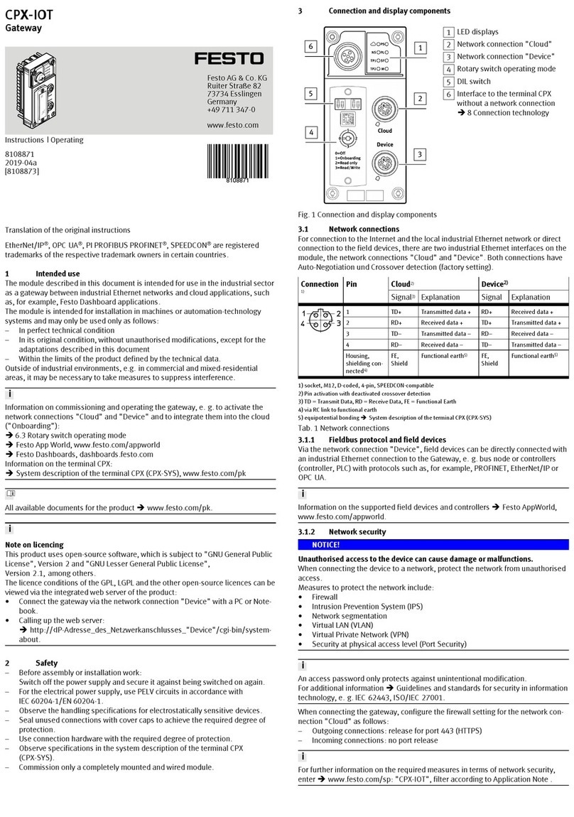
1
2
3
4
5
6
Fig.1
1
LED displays
2
"Cloud" network connection
3
"Device" network connection
4
Rotary switch for the operating
mode
5
DIL switches
6
Interface to the CPX terminal
4.2.2 LED displays
Network-specific LED displays Gateway-specific LED displays
Cloud
(blue)
‘Cloud’ network status PS
(green)
‘operating power supply’ status
NS
(red/green)
‘Device’ network status PL reserved
TP1
(green)
‘Cloud’ connection status
(Link/Traffic)
SF
(red)
System errors
TP2
(green)
‘Device’ connection status
(Link/Traffic)
M
(yellow)
Module status
Tab. 3: LED displays
Normal operating status
Behaviour of the LED displays in the normal operating status:
–The [PS] and [NS] LEDs are green.
–The [Cloud] LED is blue.
–The [TP1] and/or [TP2] LEDs are steady green or flashing green.
–The [PL], [SF] and [M] LEDs are off.
Module location
The [PS], [PL] and [NS] flash synchronously.
4.2.3 Switching elements
12
3
Fig.2
1
DIL switch 1
2
DIL switch 2
3
Rotary switch for the operating
mode
DIL switches
DIL switch 1 Description
1: OFF
2: OFF
(delivery status)
reserved
1: ON
2: ON
reserved
Tab. 4: DIL switch 1
DIL switch 2 Description
1: OFF
2: OFF
(delivery status)
reserved
1: OFF
2: ON
reserved
5.
DIL switch 2 Description
1: ON
2: OFF
è 8.2.2 Resetting web server SSL certificates to fac-
tory setting
1: ON
2: ON
è 8.2.1 Reset gateway to factory setting
Tab. 5: DIL switch 2
Rotary switch for the operating mode
Switching position Operating mode/function
0: Off –‘Cloud’ network connection is deactivated (interface switched
off).
–No communication with the MQTT broker network and no com-
munication with field devices.
1: Onboarding reserved
2: Read only –Gateway sends process data of the configured field devices to
configured MQTT brokers.
–Manual adding of field devices is enabled.
–Automatic adding of field devices via the Auto-Scan function is
blocked.
–Removal of field devices is blocked.
3: Read/Write –The gateway sends process data from the configured field
devices to the MQTT broker network.
–Manual adding of field devices is enabled.
–Automatic adding of field devices via the Auto-Scan function is
enabled.
–Parameters of connected devices can be changed.
Tab. 6: Rotary switch for the operating mode
4.2.4 Network connections
There are 2 Industrial Ethernet interfaces on the gateway for connection to an
MQTT broker and for the Industrial Ethernet network with connection to field
devices. The ‘Cloud’ and ‘Device’ network connections. Both connections have
auto-negotiation and crossover detection.
The following table shows the pin allocation with deactivated Crossover detection:
Connection Pin Cloud Device
Signal Explanation Signal Explanation
1 TD+ Transmitted data + RD+ Received data +
2 RD+ Received data + TD+ Transmitted data +
3 TD– Transmitted data – RD– Received data –
4 RD– Received data – TD– Transmitted data –
Shielding1) FE,
Shield
Functional earth FE,
Shield
Functional earth
1) connected to functional earth via RC link
Tab. 7: Network connections
4.2.4.1 MQTT broker
The connection to an MQTT broker is established via the ‘Cloud’ network connec-
tion.
4.2.4.2 Fieldbus protocol and field devices
The ‘Device’ network connection can be used to connect field devices with an
Industrial Ethernet connection directly to the Gateway, e.g. bus nodes or control-
lers (controller, PLC) with protocols such as PROFINET, EtherNet/IP or OPC UA.
4.2.5 Connection technology
The M12 socket [6] (è Fig. 1) can be used to connect a CPX terminal without
network connection, i.e. without Industrial Ethernet connection, directly to the
gateway.
Connection Connecting hardware Cover cap
‘Cloud’ network connection NECU-M-S-D12G4-C2-ET plug ISK-M12
‘Device’ network connection
Interface to the CPX terminal
without network connection
NEBC-M12G5-S-1.5-N-M12G5 con-
necting cable
Tab. 8: Connection technology
5 Assembly
WARNING
Risk of injury due to electric shock.
• For the electric power supply, use PELV circuits that guarantee a reliable electric
disconnection from the mains network.
•Observe IEC 60204-1/EN 60204-1.
• Connect all circuits for the operating and load voltage supply.
NOTICE
Material damage due to incorrect mounting.
Select screws that are suitable for the material of the interlinking block:
• Polymer: thread-grooving screws
•Metal: screws with metric thread
When ordering a single gateway, all the required screws are included.
The gateway is mounted in an interlinking block of the CPX terminal.
–Version 1:
Gateway in an interlinking block with system supply, e.g. CPX-GE-EV-S-...
–Version 2:
Gateway in an interlinking block without system supply between two end
plates with system supply, e.g. CPX-EPL-EV-S-...
1
2
3
2
2
2
Fig. 3: Mounting (version 1)
1Gateway CPX-IOT
2Screw
3Interlinking block
(with system supply)
1. Check the seal and the seal surfaces.
2. Replace damaged seal.
3. Push the gateway carefully and without tilting into the interlinking block up to
the stop.
4. Screw the screws into the existing thread.
Tighten the screws in crosswise.
–Tightening torque: 1 Nm ± 10%
6 Installation
6.1 General information about installation
WARNING
Risk of injury due to electric shock.
• For the electric power supply, use PELV circuits that guarantee a reliable electric
disconnection from the mains network.
•Observe IEC 60204-1/EN 60204-1.
• Connect all circuits for the operating and load voltage supply.
NOTICE
Short circuit as a result of ingress of liquids or foreign matter.
Damage to the electronics or malfunction.
• Use connection hardware with the required degree of protection.
•Use cover caps to seal unused connections.
• Only operate the product with cover for DIL and rotary switches mounted.
The operating and load voltage supply is via an interlinking block with system
supply or via an end plate with system supply.
Information on power supply:
è System description of the CPX terminal (CPX-SYS)
è Pin allocation power supply connection (CPX-PIN-BEL)
Comply with the handling specifications for electro-statically sensitive devices.
NOTICE
Unauthorised Access to the Device Can Cause Damage or Malfunction.
• When connecting the device to a network, protect the network from unauthor-
ised access.
Standards for security in information technology can be used for network
protection measures, e.g. IEC 62443, ISO/IEC 27001.
7 Commissioning
7.1 Selecting operating mode of the gateway
A gateway operating mode must be selected to establish a connection to an MQTT
broker è Rotary switch for the operating mode.
The rotary switch must be set to [Read only] or [Read/Write] to establish a connec-
tion to the MQTT broker and to the field devices.
7.2 Parameterisation
The gateway is parameterised via the integrated web server of the gateway.
Alternatively, certain settings can be made via the ‘Festo Field Device Tool’ (FFT) or
via the ‘Festo Automation Suite’ (FAS).
1. Connect the gateway to a PC or notebook via the ‘Device’ network connection.
2. Call the web server:
https://<IP_address_of_the_network_connection_‘Device’>
ÄThe warning that the web server does not have a secure SSL certificate is
displayed.
A server certificate suitable for the IT infrastructure can be installed in
the ‘Configuration’ > ‘Web server SSL certificate’ menu bar.
3. Logging in:
–User name: admin
–Password (factory setting): CPX-IOT Product Key on the type plate,
e.g. 3S7PMM2M93V
7.3 Configuring MQTT broker
1. Call the web server:
https://<IP_address_of_the_network_connection_‘Device’>
2. To parameterise the MQTT broker, select ‘MQTT’ > ‘Broker Configuration’ in
the menu bar.
3. To perform a connection test, select ‘MQTT’ > ‘Send Test Message’ in the
menu bar.
7.4 Configure field device or IOT data source
1. Call the web server:
https://<IP_address_of_the_network_connection_‘Device’>
2. To configure field devices or IOT data sources, select ‘Devices’ > ‘Manage
Devices’ in the menu bar.
7.5 Querying firmware information
The firmware version and firmware updates can be queried via the
‘Festo Field Device Tool’ (FFT) or the ‘Festo Automation Suite’ (FAS).
7.6 Performing firmware update
Firmware, software or configuration files è www.festo.com/sp.
1. Enter ‘Festo Field Device Tool’ into search.
2. Select software in the ‘Software/Downloads’ section.
3. Download and install the current version of the ‘Festo Field Device Tool’.
8Malfunctions
8.1 Diagnostics
8.1.1 ‘Cloud’ network status
LED status Meaning Error handling
blue light
Normal operating status:
Network connection to MQTT
broker established.
—
flashes
blue 1x
Establishment or restoration of a
connection to the MQTT broker.
—
flashes
blue 2x
Network error –Check configuration,
e.g.
DHCP address assignment,
static IP address.
off
No connection to the MQTT
broker.
–Check network connection.
Tab. 9: ‘Cloud’ network status (LED with cloud symbol)
8.1.2 ‘Device’ network status
LED status Meaning Error handling
green
light
Normal operating status:
The gateway is connected with
field devices.
—
flashing
green
No connection to field devices:
The gateway has received an IP
address, but is not yet connected
with field devices.
–Check configuration.
–Check module status.
–Restart module.
–Repeat Onboarding.
red light
Communication with the field
devices has failed:
non-permitted network configura-
tion, e.g. already used IP address
set.
–Check configuration,
e.g.
DHCP address assignment,
static IP address.
LED status Meaning Error handling
flashing
red
Communication with the field
devices has failed:
Network connection faulty,
e.g. connecting cable interrupted.
–Check device connection.
off
The gateway is offline. –Check network connection.
Tab. 10: ‘Device’ network status ([NS] LED)
8.1.3 Module status
LED status Meaning Error handling
off
Normal operating status:
The gateway is in the [Off], [Read
only] or [Read/Write]è Rotary
switch for the operating mode
operating mode
—
flashes
yellow 3x
Onboarding devices active:
The gateway performs a network
scan.
The gateway is in the [Read/
Write] operating mode è Rotary
switch for the operating mode.
—
yellow
light
The gateway is in the [Off] or
[Onboarding] operating mode.
There is no communication with
the MQTT broker and no com-
munication with field devices
è Rotary switch for the oper-
ating mode.
–Set rotary switch to [Read only]
or [Read/Write].
Tab. 11: Module status ([M] LED)
8.1.4 ‘Cloud’ connection status
LED status Meaning Error handling
green
light
Normal operating status:
Network connection established.
–
flashing
green
Data traffic1) –
off
No network connection –Check network connection.
1) The flashing frequency depends on the traffic.
Tab. 12: ‘Cloud’ connection status ([TP1] LED)
8.1.5 ‘Device’ connection status
LED status Meaning Error handling
green
light
Normal operating status:
Network connection to the field
devices has been established.
–
flashing
green
Data traffic1) –
off
No network connection –Check network connection.
1) The flashing frequency depends on the traffic.
Tab. 13: ‘Device’ connection status ([TP2] LED)
8.1.6 ‘operating power supply’ status
LED status Meaning Error handling1)
green
light
Normal operating status:
Operating voltage applied.
–
LED status Meaning Error handling1)
flashing
green
Undervoltage:
Operating voltage outside the tol-
erance range.
–Rectify undervoltage.
off
Operating voltage is not present. –Check operating voltage
supply.
1) General information on the PS LED è System description of CPX terminal (CPX-SYS)
Tab. 14: ‘Operating power supply’ ([PS] LED)
8.1.7 System errors
LED
(red)
Sequen
ce
Meaning Error handling
off
Normal operating status:
No error
–
flashes
red 1x
Minor error/information
(error class 1)
è System description of the
CPX terminal (CPX-SYS)
flashes
red 2x
Error
(error class 2)
flashes
red 3x
Serious error, internal error,
e.g. hardware error
(error class 3)
Tab. 15: System errors ([SF] LED)
8.2 Malfunction messages
8.2.1 Reset gateway to factory setting
1. Switch off the power supply.
2. Set DIL switch 2 to [ON].
3. Switch on the power supply.
ÄThe [M] LED flashes quickly for a few seconds.
•Do not switch off the power supply.
• Do not actuate the DIL switch.
4. If the LED [M] stops flashing, set the DIL switch 2 to [OFF].
ÄThe gateway has returned to the factory setting.
8.2.2 Resetting web server SSL certificates to factory setting
1. Switch off the power supply.
2. Set DIL switch 2.1 to [ON].
3. Set DIL switch 2.2 to [OFF].
4. Switch on the power supply.
ÄThe [M] LED flashes quickly for a few seconds.
•Do not switch off the power supply.
• Do not actuate the DIL switch.
5. When the [M] LED stops flashing, set DIL switch 2 to [OFF].
ÄThe web server SSL certificates are reset to factory settings.
9 Disassembly
1. Switch off the power supply and secure it against being switched on again.
2. Unscrew the screws.
3. Pull the gateway out of the interlinking block without tilting it.
10 Technical data
Property Specification/value
General technical data è System description of the CPX terminal
(CPX-SYS)
Power supply
Operating power supply UEL/SEN [V DC] 24 ± 25 %
Intrinsic current consumption at nominal
operating voltage 24 V from operating
voltage supply UEL/SEN
[mA] Typically 80
(internal electronics)
Mains buffering time [ms] 10
Separation of network interface from oper-
ating voltage supply UEL/SEN
Galvanic
Property Specification/value
Degree of protection by housing in accord-
ance with IEC 60529, completely mounted,
plug connector inserted or cover cap
installed.
With power supply connection:
–via interlinking block IP65/IP67
–via end plate IP20
Connection technology
Network connections 2 × sockets, M12, D-coded, 4-pin,
SPEEDCON-compatible
Interface to terminal CPX
without a network connection
1 × socket, M12, A-coded, 5-pin
Network-specific characteristics
IP configuration (factory settings) Cloud DHCP
Device IP address: 192.168.0.1
Subnet mask: 255.255.255.0
Data transfer to the MQTT broker MQTT version 3.1.1
Transmission technology Industrial Ethernet, Switched Fast Ethernet
Specification IEEE 802.3u (100Base-TX)
Transmission rate [Mbit/s] 10/100 (full duplex/half duplex)
Crossover detection Auto-MDI/MDI-X
Number of devices (‘Device’ network con-
nection)
maximum 10
More devices can be operated depending
on the application.
Cable specification
Cable type Ethernet twisted pair cable, shielded
(Shielded Twisted Pair, STP)
Transmission class (Link Class) Cat 5 category
Cable diameter1) [mm] 6 … 8
Wire cross section)2) [mm2]0.14 … 0.75
Cable length [m] maximum 100
1) When using the plug NECU-MS-D12G4-C2-ET
2) 22 AWG required for max. connection length between network participants (end-to-end link)
Tab. 16: Technical data

Other Festo Gateway manuals

Festo CPX-IOT User manual

Festo

Festo CPX-IOT User manual

Festo CESA-GW-AS-PB User manual

Festo

Festo CESA-GW-AS-PB User manual

Festo CESA-GW-AS-CO User manual

Festo

Festo CESA-GW-AS-CO User manual

Popular Gateway manuals by other brands

SICK Flexi Gateway GETC1 Operating

SICK

SICK Flexi Gateway GETC1 Operating

AudioCodes MediaPack MP-402 user manual

AudioCodes

AudioCodes MediaPack MP-402 user manual

Skype ITA user guide

Skype

Skype ITA user guide

Lucent Technologies PacketStar PSAX 2300 user guide

Lucent Technologies

Lucent Technologies PacketStar PSAX 2300 user guide

JK Audio BlueKeeper user guide

JK Audio

JK Audio BlueKeeper user guide

RTA 460ECPS-N2EW Product user guide

RTA

RTA 460ECPS-N2EW Product user guide

Ingics iGS03W user guide

Ingics

Ingics iGS03W user guide

Alula RE929X Series manual

Alula

Alula RE929X Series manual

Funkwerk bintec R1200 manual

Funkwerk

Funkwerk bintec R1200 manual

AMX AXB-NET Specifications

AMX

AMX AXB-NET Specifications

Crestron C2N-IRGW-F Operations & installation guide

Crestron

Crestron C2N-IRGW-F Operations & installation guide

Funkwerk bintec R230a user guide

Funkwerk

Funkwerk bintec R230a user guide

ZyXEL Communications ZyXEL ZyWALL 30W quick start guide

ZyXEL Communications

ZyXEL Communications ZyXEL ZyWALL 30W quick start guide

AudioCodes Mediant 4000 SBC user manual

AudioCodes

AudioCodes Mediant 4000 SBC user manual

Telular phonecell sx5e user manual

Telular

Telular phonecell sx5e user manual

Unitronics GW-BAC1 user guide

Unitronics

Unitronics GW-BAC1 user guide

Midea M-INTERFACE Installation & owner's manual

Midea

Midea M-INTERFACE Installation & owner's manual

hilscher netTAP NT 50 Series user manual

hilscher

hilscher netTAP NT 50 Series user manual

manuals.online logo
manuals.online logoBrands
  • About & Mission
  • Contact us
  • Privacy Policy
  • Terms and Conditions

Copyright 2025 Manuals.Online. All Rights Reserved.