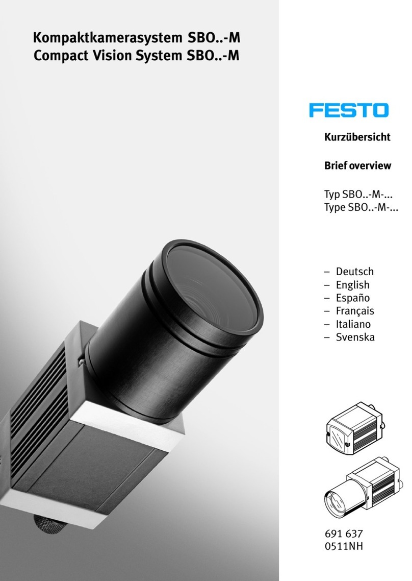
Festo SBO*-M-* Series User manual

Electronics Manual
Manual
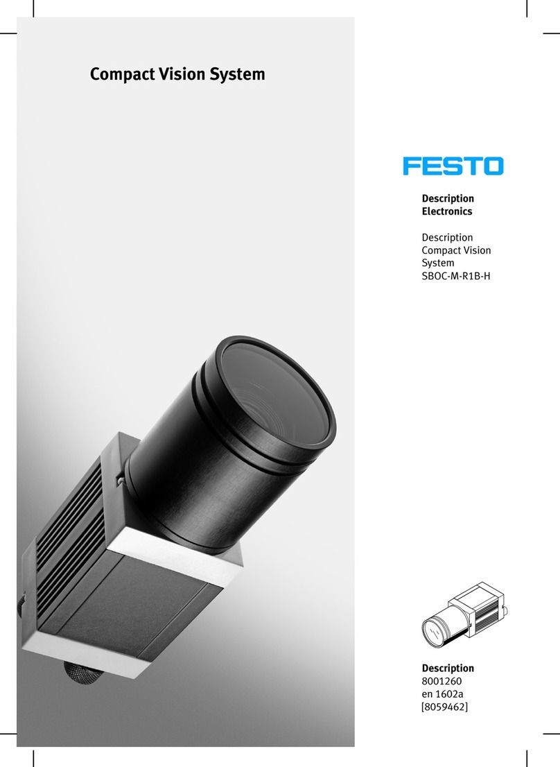
Compact Vision
System
Type SBO..−M−...
Manual
542 123
en 0511NH
[691 639]
Compact Vision System


Contentsand general instructions
I
FestoP.BE−SBO−M−EN en 0511NH
Original de. ......................................
Editionen 0511NH. ................................
DesignationP.BE−SBO−M−EN.........................
Order no. 542123. ................................
©(FestoAG&Co. KG, D73726 Esslingen, Federal Republic
of Germany, 2005)
Internet: http://www.festo.com
E−Mail:service_international@festo.com
Thereproduction, distribution and utilization of this document
as well as thecommunicaton of itscontentstootherswithout
express authorization is prohibited.Offenderswill beheld
liable for thepayment of damages. All rightsreserved in the
event of thegrant of apatent, utility module or design.

Contentsand general instructions
II FestoP.BE−SBO−M−EN en 0511NH
Trademarks
Harax®is aregistered trademark of HARTING Electronics
GmbH& Co. KG
Harting RJ Industrial®is aregistered trademark of HARTING Electronics
GmbH& Co. KG

Contentsand general instructions
III
FestoP.BE−SBO−M−EN en 0511NH
Contents
Designated use V........................................................
Areas of application and approval by authorities VI.............................
Safety instructionsVII.....................................................
Service VIII...............................................................
Target group VIII..........................................................
Important user instructionsIX..............................................
Notes on theuse of this manual XI...........................................
Product−specific terms and abbreviationsXII...................................
1. System summary 1−1. . . . . . . . . . . . . . . . . . . . . . . . . . . . . . . . . . . . . . . . . . . . . . .
1.1 Structureof theCompact Vision System typeSBO..−M−R1B 1−3.............
1.2 Variants1−5.......................................................
1.2.1 Method of operation1−6.....................................
1.2.2 Display and connecting elements1−7...........................
1.3 FCT software(functional overview) 1−9.................................
1.4Lensselection with typeSBOC−M−R1B 1−10..............................
2. Fitting 2−1. . . . . . . . . . . . . . . . . . . . . . . . . . . . . . . . . . . . . . . . . . . . . . . . . . . . . . . .
2.1 Fitting 2−3........................................................
2.1.1 Dimensionsof theCompact Vision System typeSBO..−M 2−3........
2.1.2 Fitting theCompact Vision System 2−4..........................
2.1.3 Fastening with adapter kit typeSBOA−HMSV−39 2−5...............
2.1.4Fitting/dismantling of lensand protectivetubing
(only SBOC−...)2−6..........................................

Contentsand general instructions
IVFestoP.BE−SBO−M−EN en 0511NH
3. Installation 3−1. . . . . . . . . . . . . . . . . . . . . . . . . . . . . . . . . . . . . . . . . . . . . . . . . . .
3.1 General instructionson installation3−3................................
3.1.1 Selecting thepower unit3−5..................................
3.2 Electrical connections3−6...........................................
3.2.1 Connecting theoperating voltagesupply and theI/Os 3−6.........
3.2.2 Connecting theEthernet interface 3−10..........................
3.2.3 CAN interface 3−14...........................................
4. Commissioning 4−1. . . . . . . . . . . . . . . . . . . . . . . . . . . . . . . . . . . . . . . . . . . . . . . .
4.1 Instructionson commissioning 4−3....................................
4.1.1 Installing and starting theFCT4−3.............................
4.1.2 Stepsfor commissioning 4−4..................................
4.2 Addressing in theEthernet (basics)4−5................................
4.3 Setting thenetwork with theCompact Vision System 4−8
..................
4.4Instructionson operation4−11.........................................
4.4.1 Setting thelens4−12.........................................
4.4.2 Trigger signal 4−14...........................................
5. Diagnosis and error treatment 5−1. . . . . . . . . . . . . . . . . . . . . . . . . . . . . . . . . . . .
5.1 General diagnostic possibilities 5−3............................
5.1.1 Statusdisplay5−3..........................................
5.1.2 Eliminating faults5−6........................................
A. Technical appendix A−1
. . . . . . . . . . . . . . . . . . . . . . . . . . . . . . . . . . . . . . . . . . . . .
A.1 Careand maintenance A−3...........................................
A.2 Accessories A−4
....................................................
A.3 SiemensstarA−5...................................................
A.4Technical specificationsA−7..........................................
B. Index B−1. . . . . . . . . . . . . . . . . . . . . . . . . . . . . . . . . . . . . . . . . . . . . . . . . . . . . . . . .
B.1 IndexB−3.........................................................

Contentsand general instructions
V
FestoP.BE−SBO−M−EN en 0511NH
Designated use
TheCompact Vision System typeSBO..−M−... has been
designed for fitting intoamachineor intoan automated
system. It serves for visualizing and diagnosing fast
movement sequences.
TheCompact Vision System typeSBO..−M−... may only be
used as follows:
only in industrial applications
in accordance with designated use
without any modificationsby theuser.Only theconver
sionsor modificationsdescribed in thedocumentation
supplied with theproduct arepermitted.
in faultless technical condition.
When used together with commercially available compo
nents, such as sensorsand actuators, thespecified limitsfor
pressures, temperatures, electrical data, torques etc. must be
observed.National and local safety regulationsmust also be
observed.

Contentsand general instructions
VIFestoP.BE−SBO−M−EN en 0511NH
Areas of application and approval by authorities
Theproduct fulfils therequirementsof theEU guidelines and
is marked with theCE symbol.
Standardsand test values, which theproduct must observe
and fulfil, can befound in thesection Technical specifica
tions".Theproduct−relevant EU directivecan befound in the
conformity declaration.
Product designs, which aremarked with thefollowing sym
bol, fulfil therequirementsof the:
Recognized Component Marksfor Canadaand theUnited
States
Only for use in Class 2Circuits.
Please note
Notethefollowing if your application must comply with the
specificationsof theRecognized Component Marksfor
Canadaand theUnited States":
Rules for observing theUL approval can befound in the
UL−specific brief operating instructions. Therelevant
technical specificationslisted therealso apply here.
Thetechnical specificationsin this documentation may
show different values.

Contentsand general instructions
VII
FestoP.BE−SBO−M−EN en 0511NH
Safety instructions
Caution
During commissioning and programming, thesafety re
gulationslisted in this manual and in thedocumentation
for thecontroller and theother componentsused must
alwaysbeobserved.
Theuser must ensurethat nobody has access tothe
positioning rangeof theconnected actuators. Access to
thepossible danger area must beprevented by suitable
measures such as protectivescreensand warning signs.
Caution
Electrostatically sensitivecomponents. Electrostatic
discharges can damagetheinternal electronics.
·Donot open thehousing.Observetheregulationsfor
handling electrostatically sensitivecomponents.
Caution
A dirty and scratched lensor adirty and scratched protec
tivedisc can lead tooptical faults. Makesurethat thelens
and theprotectivedisc arenot scratched.Donot use any
abrasivecleaning agents.
Clean thethelensor theprotectivedisc if they aredirty or
if therearedirt depositson them:
with an air gun or with clean non−lubricated compresed
air.
with asoft moist cloth and non−abrasivecleaning agents.

Contentsand general instructions
VIII FestoP.BE−SBO−M−E N en 0511NH
Caution
If thepermitted temperaturerangeis exceeded, e.g.by
powerfulexternal sources of light, this can lead tosystem
faultsand cause damage.
·Fit theCompact Vision System in awell ventilated
location, especially screened from theheat emitted by
other devices and from sources of light.
Service
Please consult your local Festorepair service if you haveany
technical problems.
Target group
This manual is intended exclusively for technicianstrained in
control and automation technology whohaveexperience in
installing and commissioning electronic systems.

Contentsand general instructions
IX
FestoP.BE−SBO−M−EN en 0511NH
Important user instructions
Danger categories
This manual containsinstructionson thepossible dangers
which may occur if theproduct is not used correctly.These
instructionsaremarked (Warning, Caution, etc.), printed on a
shaded background and marked additionally with apicto
gram. A distinction is madebetween thefollowing danger
warnings:
Warning
This meansthat failuretoobservethis instruction may
result in seriouspersonal injury or damagetoproperty.
Caution
This meansthat failuretoobservethis instruction may
result in personal injury or damagetoproperty.
Please note
This meansthat failuretoobservethis instruction may
result in damagetoproperty.
Thefollowing pictogram markspassages in thetext which
describeactivities with electrostatically sensitivecompo
nents.
Electrostatically sensitivecomponentsmay bedamaged if
they arenot handled correctly.

Contentsand general instructions
XFestoP.BE−SBO−M−EN en 0511NH
Marking special information
Thefollowing pictograms mark passages in thetext
containing special information.
Pictograms
Information:
Recommendations, tipsand references toother sources of
information.
Accessories:
Information on necessary or sensible accessories for the
Festoproduct.
Environment:
Information on environment−friendly use of Festoproducts.
Text markings
·Thebullet indicates activities which may becarried out in
any order.
1. Figures denoteactivities which must becarried out in the
numerical order specified.
Hyphensindicategeneral activities.

Contentsand general instructions
XI
FestoP.BE−SBO−M−EN en 0511NH
Notes on the use of this manual
Please note
This manual referstothefollowing versions:
Hardware/software Version
Compact Vision System
SBO..−M−...
as from softwarestatus1.0.0.0
as from hardwarestatusAB0905
FestoConfiguration Tool FCTas from version 1.0.10
PlugIn SBO..−M network" as from version 1.00
Tab.0/1:Hardwareand softwarestates
This manual containsgeneral basic information on fitting,
installing and operating theCompact Vision System. Informa
tion on commissioning, parametrizing and diagnosing with
theFestoConfiguration Tool" can befound in thehelp
system for thesoftware.
Type Title Contents
Electronics manual
(this manual)
Compact Vision System type
SBO..−M−...
Fitting, installing and operating
theCompact Vision System
Help system for theFCT
software
Help for theFCT
(contained in FCT software)
Function description of the
FestoConfiguration Tool
Help system for thePlugIn
SBO..−M network"
Help for theSBO..−M network" Function description for the
PlugIn SBO..−M network"
Tab.0/2:Documentation on theCompact Vision System

Contentsand general instructions
XII FestoP.BE−SBO−M−EN en 0511NH
Product−specific terms and abbreviations
Thefollowing product−specific abbreviationsareused in this
manual:
Term/abbreviation Meaning
0−signal Input or output supplies 0V
1−signal Input or output supplies 24 V
Amplification See sensor amplification
Aperture Opening through which light passes through thelensontotheimage
converter surface. Thelarger theopening or theapertureis, themorelight
will reach thesensor.When theapertureopens, thedepth of focuswill be
reduced.Thedepth of focusincreases thefurther theapertureis closed
(larger f−number).Small apertureopeningsmakelonger exposuretimes
necessary.Shorter exposuretimes requirelarger apertureopenings.
AutoMDI−X Recognizes theconfiguration of theother station and adaptsthesend and
receivecables of anetwork connection automatically.
CMOS sensorOptoelectronic sensor which convertslight signals intoelectric signals. In
addition tothepurely sensor function, functionsfor imageconversion are
integrated intothechip, e.g.lighting check and contrast correction.
Depth of field See depth of focus
Depth of focusThespatial area in front of and behind thefocussed object which is still
sharp (also known as depth of field).Thedepth of field dependson thefocal
depth of thelensand theset aperture. Short focal depthswith small
apertureopeningslead tolarger depth of field.
Ethernet Physical protocol and network for connecting variousdevices
Exposuretime Thetime during which theCMOS sensor is subjected tolight during
recording.Thelonger theexposuretime, themorelight will penetrate.
Thechoice of exposuretime dependse.g.on themovement speed, the
light available and thelight sensitivity of thesensor (see also sensor
amplification).With moving objectsexcessiveexposuretimes result in
blurred images.
FCT FestoConfiguration Tool is thesoftwarepackagefor configuring and
commissioningvariuscomponentsand devices from Festo.

Contentsand general instructions
XIII
FestoP.BE−SBO−M−EN en 0511NH
Term/abbreviation Meaning
Focal depth Long focal depthscreatealargeimage, short focal depthscreatea
wide−angle image. Lenses with variable focal depthsareknown as zoom
lenses. Lenses with longer focal depthsusually haveless depth of focusand
less light intensity.
I Digital input
ODigital output
PLC/IPCProgrammable logic controller/industrial PC
PlugIn Additional module which extendsthefunctionality of aprogram. PlugInsfor
theFCT softwarepackageextend thefunctionality of theFCT with regard to
theuse of special devices.
Sensor amplification Influences thelight sensitivity of thesensor.If theamplification is in
creased, thelight sensitivity will also beincreased.Excessiveamplification
can lead tograined images.
TCP/IP Combination of theprotocols TCP and IP, themost−widely used protocol in
communication via Ethernet.
Tab.0/3:Product−specific terms and abbreviations

Contentsand general instructions
XIVFestoP.BE−SBO−M−EN en 0511NH

System summary
1−1FestoP.BE−SBO−M−EN en 0511NH
Chapter 1

1. System summary
1−2FestoP.BE−SBO−M−EN en 0511NH
Contents
1. System summary 1−1. . . . . . . . . . . . . . . . . . . . . . . . . . . . . . . . . . . . . . . . . . . . . . .
1.1 Structureof theCompact Vision System typeSBO..−M−R1B 1−3.............
1.2 Variants1−5.......................................................

1.2.1 Method of operation1−6.....................................

1.2.2 Display and connecting elements1−7...........................
1.3 FCT software(functional overview) 1−9.................................
1.4Lensselection with typeSBOC−M−R1B 1−10..............................

1. System summary
1−3
FestoP.BE−SBO−M−EN en 0511NH
1.1 Structure of the Compact Vision System type SBO..−M−R1B
ComponentsTheCompact Vision System typeSBO..−M−R1B is an intelli
gent high−speed camerawith integrated electronics for
imageprocessing and communication.It is contained in a
compact and robust housing and offers:
an imagereproducing CMOS sensor (resolution 640x 480
pixels; ½ inch; monochrome) with high frame rate(max.
185pictures per second with full resolution; reduced
resolutionsenable higher frame rates)
interfaces for communication and for connecting external
devices
with typeSBOI−M−R1B:
an integrated lensand integrated LED lighting
with typeSBOC−M−R1B:
astandardized C−mount lenssocket (suitable lenses as
well as optical accessories such as filtersand other lenses
areobtainable on demand).
FunctionTheCompact Vision System enables you touse at low cost
optical test devices in your machines and plantsfor visualiz
ing and analysing fast movement sequences, e.g.for ascer
taining faults.
Configuration, commissioning and operation arecarried out
with thesoftwarepackageFestoConfiguration Tool".
User−specific firmwareversionscan beloaded intothedevice
for special applications.

1. System summary
1−4 FestoP.BE−SBO−M−EN en 0511NH
Networking and control TheCompact Vision System can belinked directly tothePC
via theEthernet interface. Several Compact Vision Systems
can benetworked with each other in conjunction with ahub
or switch, in order torecord amovement sequence from
several sides at thesame time. Recordingscan becontrolled
via digital I/Os or by aPC.
1Compact Vision
System (here
typeSBOC−M−...)
2PCwith Festo
Configuration
Tool" FCT
1
2
Fig.1/1:Direct networking with thePC
1
2
3
1Hub/switch
2PCwith FestoConfiguration Tool" FCT
3Compact Vision System
(heretypeSBOC−M−...)
Fig.1/2:Cameranetwork
This manual suits for next models
3
Table of contents
Other Festo Machine Vision System manuals
Popular Machine Vision System manuals by other brands

Allied Vision
Allied Vision MAKO U-029B Technical manual

National Instruments
National Instruments NI Vision CVS-1450 Series Getting started

Cognex
Cognex In-Sight 7010 installation manual

UNIPRODO
UNIPRODO UNI_NIGHTVISION_01 user manual

National Instruments
National Instruments NI CVS-1458RT Getting started guide

Humanware
Humanware Prodigi Connect 12 user guide

JAI
JAI GO-5000M-PGE-1 user manual

Omron
Omron FLV-FB Series instruction sheet

THine
THine THSEU101 quick start guide

National Instruments
National Instruments Vision CVS-1455 user manual

Pyle view
Pyle view PLCM35R instruction manual

Allied Vision Technologies
Allied Vision Technologies ALVIUM GMSL2 user guide