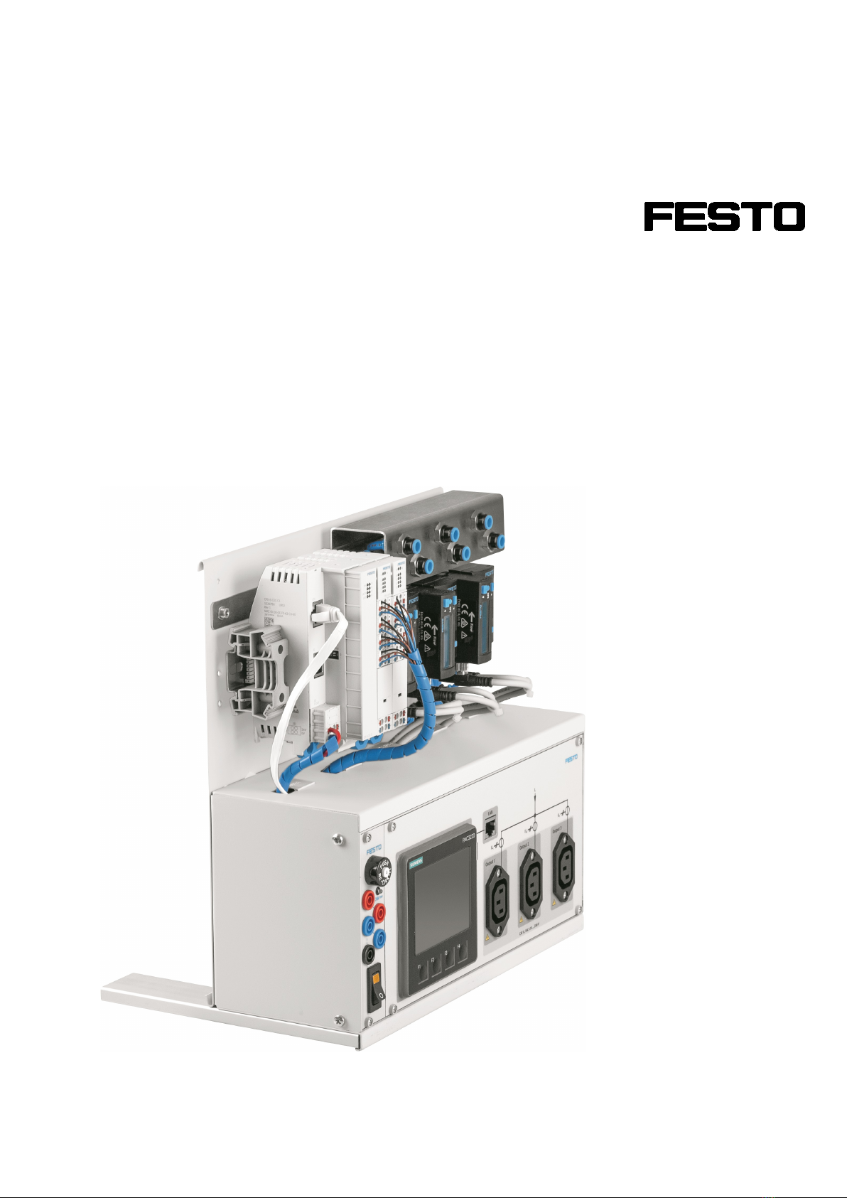
Single-Phase Energy Measurement Box – Operating Instructions
© Festo Didactic 8130877 5
Contents
1 General prerequisites for operating the devices__________________________________________6
2 Safety instructions and pictograms ____________________________________________________7
2.1 Safety instructions __________________________________________________________________7
2.2 Pictograms ________________________________________________________________________8
3 Intended use_______________________________________________________________________9
4 For your safety ___________________________________________________________________ 10
4.1 Important information _____________________________________________________________ 10
4.2 Obligations of the operating company ________________________________________________ 11
4.3 Obligations of the trainees__________________________________________________________ 11
5 Work instructions and safety precautions _____________________________________________ 12
5.1 General information _______________________________________________________________ 12
5.2 Electrical components _____________________________________________________________ 12
5.3 Pneumatic components ____________________________________________________________ 15
6 Safety sockets ___________________________________________________________________ 17
7 Technical data ___________________________________________________________________ 19
7.1 General data _____________________________________________________________________ 19
7.2 Electrical data ____________________________________________________________________ 19
7.3 Pneumatic data___________________________________________________________________ 20
7.4 Approvals _______________________________________________________________________ 20
8 Description ______________________________________________________________________ 20
8.1 Configuration ____________________________________________________________________ 21
8.2 Electrical design __________________________________________________________________ 22
8.3 Pneumatic design _________________________________________________________________ 24
8.4 Data processing __________________________________________________________________ 25
9 Commissioning___________________________________________________________________ 26
9.1 Electrical connection_______________________________________________________________ 26
9.2 Pneumatic connection _____________________________________________________________ 29
9.3 Network connection _______________________________________________________________ 30
10 Scope of delivery _________________________________________________________________ 30
11 Accessories______________________________________________________________________ 30
12 Maintenance and cleaning _________________________________________________________ 31
12.1 Cleaning ________________________________________________________________________ 31
12.2 Changing fuses ___________________________________________________________________ 32
13 Disposal ________________________________________________________________________ 32