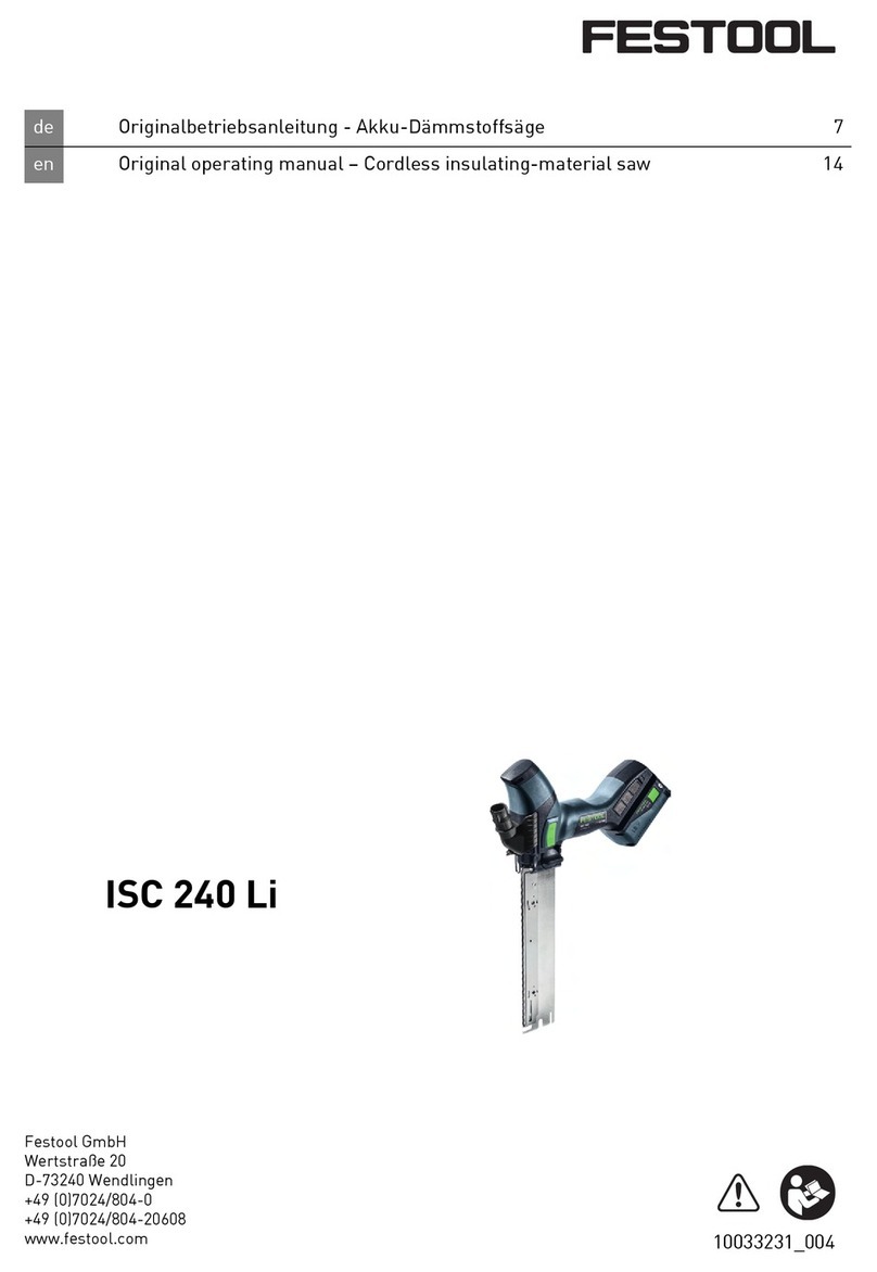
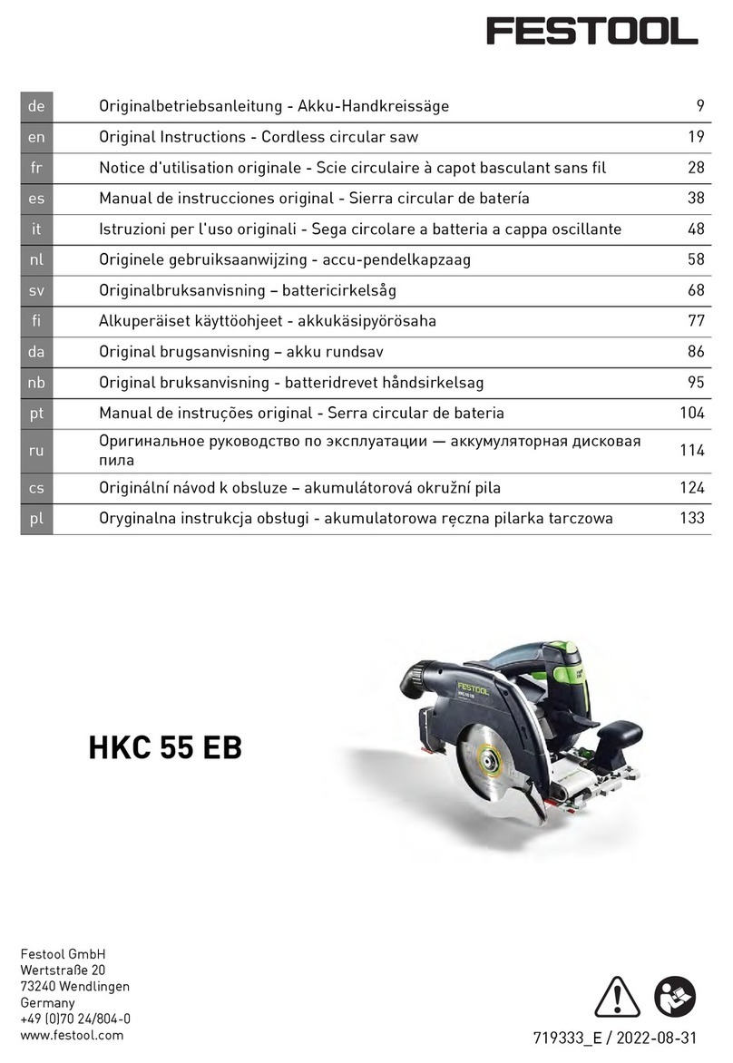
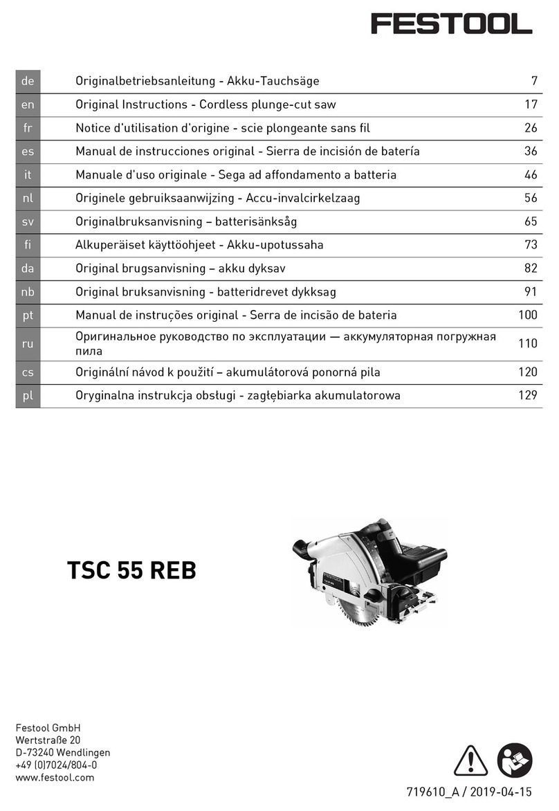
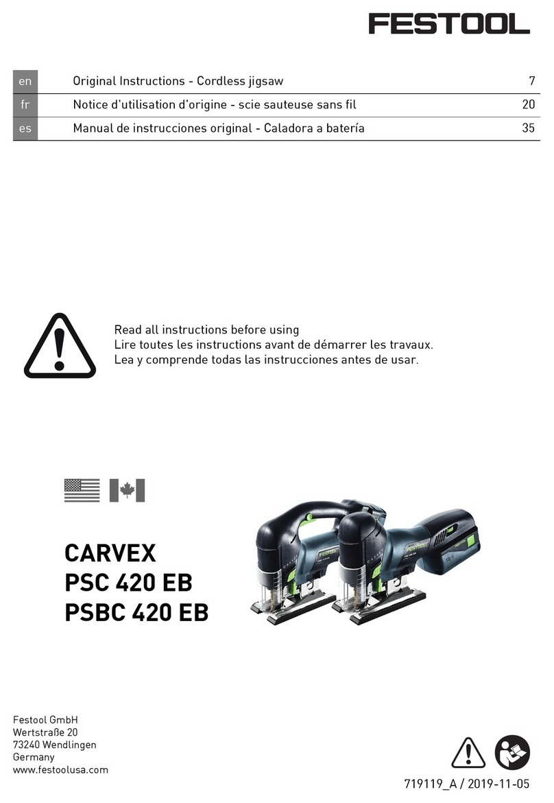
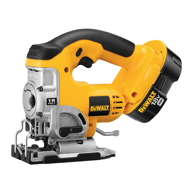
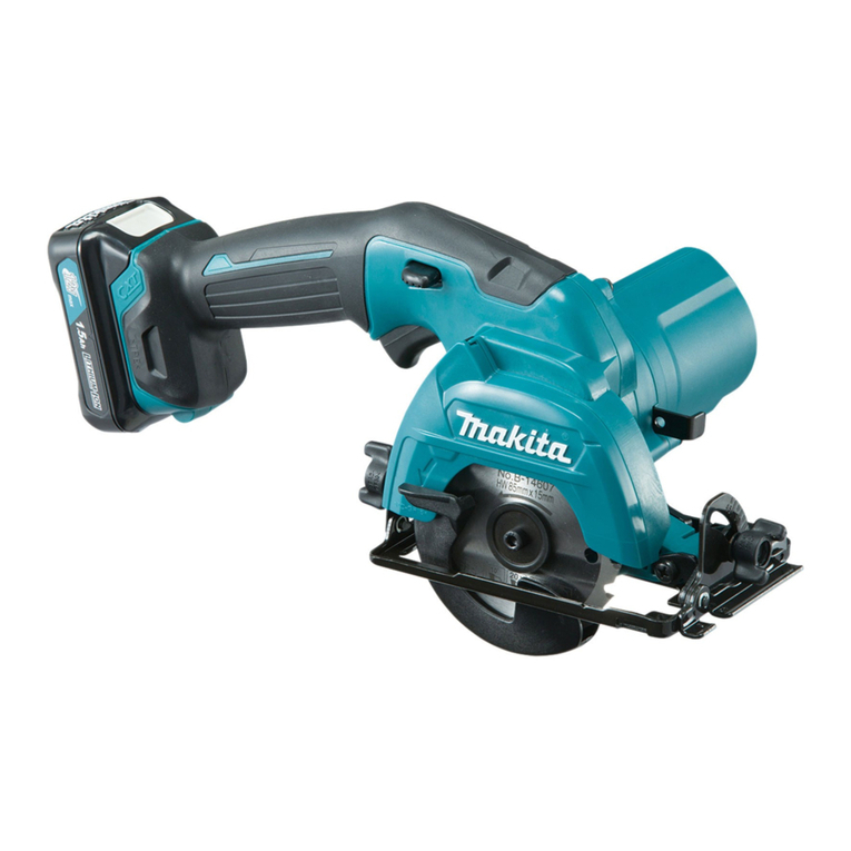
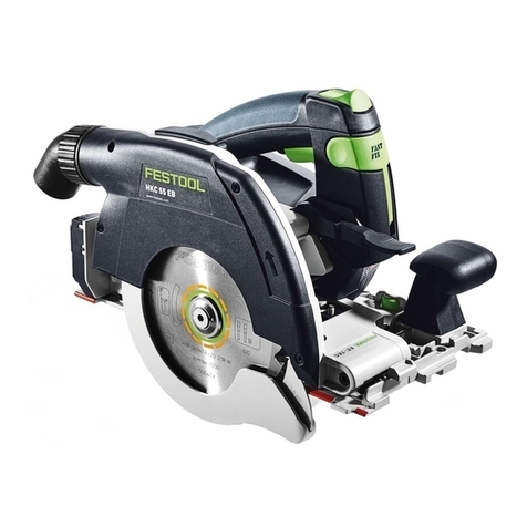
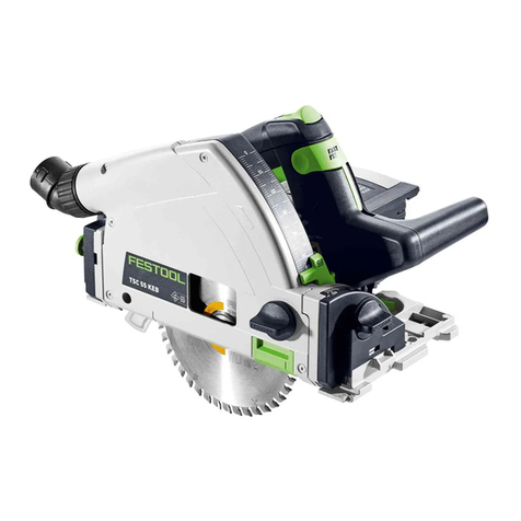
Festool TSC 55 KEB User manual

en Original Instructions - Cordless plunge-cut saw 7
fr Notice d'utilisation d'origine - scie plongeante sans fil 25
es Manual de instrucciones original - Sierra de incisión de batería 44
Read all instructions before using
Lire toutes les instructions avant de démarrer les travaux.
Lea y comprende todas las instrucciones antes de usar.
TSC 55 KEB
Festool GmbH
Wertstraße 20
73240 Wendlingen
Germany
www.festoolusa.com
721863_C / 2020-11-16


1
1-5
1-1
1-1
1-6
1-12
1-10
1-2
1-8
1-7
1-23
1-16
1-17
1-18
1-19
1-20
1-2
1-3
1-4
1-13
1-14
1-4
1-9
1-9
1-15
1-21
1-11
1-22


Contents
1 Symbols.......................................................7
2 About this manual....................................... 7
3 Safety warnings...........................................8
4 Intended use..............................................12
5 Technical data........................................... 13
6 Functional description.............................. 13
7 Battery pack.............................................. 13
8 Settings......................................................14
9 Working with the electric power tool........18
10 Service and maintenance..........................21
11 Accessories............................................... 22
12 Environment..............................................23
13 General information..................................23
1 Symbols
Warning of general danger
Warning of electric shock
Read the operating instructions and
safety instructions.
Wear ear protection.
Wear protective gloves when changing
tools and working with raw materials.
Wear a dust mask.
Wear protective goggles.
Inserting the battery pack
Removing the battery pack
Risk of pinching fingers and hands!
Maximum power with two battery
packs (36 V).
Less power with one battery pack
(18 V).
Direction of rotation of saw and the
saw blade
Kickback stop function
STOP
Electro-dynamic run-down brake
Tool contains a chip which stores data.
See section 13.1
Handling instruction
Tip or advice
d.c direct current
V volt
rpm
min-1
revolutions per minute
diameter
° angular degree
kg kilogram
lb. pound
mm millimetre
" inch
CAUTION
For
use only with FESTOOL
batteries BP 18.
ATTENTION À
utiliser seulement avec
les batteries FESTOOL
BP 18.
PRECAUCIÓN
Para uso
solamente con
las baterías FESTOOL
BP 18.
CAUTION For use only with
FESTOOL batteries BP 18
WARNING – Check guarding
system. It must cover the blade instantly!
Hold saw with both hands. Support and
clamp work.
AVERTISSEMENT
Contrôlez le système de
protection. Il doit couvrir instantanément la lame!
Tenez la scie des deux mains. Soutenez et fixez
l'ouvrage.
ADVERTENCIA Compruebe el sistema de seguridad.
Debe cubrir la espada en el acto. Sujete la sierra con
ambas manos. Tarea de apoyo y sujeción.
DANGER –
Keep hands and body
away from and to the side of
the blade. Contact with blade will
result in serious injury.
DANGER – Tenez les mains et le
corps à distance de la lame et sur le
côté de celle-ci. Tout contact avec la
lame provoque des blessures graves.
PELIGRO
– Mantenga las manos y el
cuerpo alejados de la espada y a un lado
de ella. El contacto con la espada
provocará heridas graves.
DANGER Keep hands and body away from and
to the side of the blade. Contact with blade
will result in serious injury.
WARNING Check guarding system. It must
cover the blade instantly! Hold saw with both
hands. Support and clamp work.
2 About this manual
Save these instructions
It is important for you to read and understand
this manual. The information it contains relates
to protecting your safety and preventing prob
lems. The symbols below are used to help you
recognize this information.
English
7

DANGER Description of imminent
hazard and failure to avoid
hazard will result in death.
WARN
ING
Description of hazard and
possible resulting injures
or death.
CAUTION Description of hazard and
possible resulting injuries.
NOTICE Description of possible
damage of the device or its
surroundings.
3 Safety warnings
3.1 General power tool safety warnings
WARNING! Read all safety warnings, in
structions, illustrations and specifica
tions provided with this power tool. Failure to
follow all instructions listed below may result in
electric shock, fire and/or serious injury.
Save all warnings and instructions for future
reference.
The term "power tool" in the warnings refers to
your mains-operated (corded) power tool or
battery-operated (cordless) power tool.
1 WORK AREA SAFETY
a. Keep work area clean and well lit. Clut
tered or dark areas invite accidents.
b. Do not operate power tools in explosive
atmospheres, such as in the presence of
flammable liquids, gases or dust. Power
tools create sparks which may ignite the
dust or fumes.
c. Keep children and bystanders away while
operating a power tool. Distractions can
cause you to lose control.
2 ELECTRICAL SAFETY
a. Power tool plugs must match the outlet.
Never modify the plug in any way. Do not
use any adapter plugs with earthed
(grounded) power tools. Unmodified plugs
and matching outlets will reduce risk of
electric shock.
b. Avoid body contact with earthed or
grounded surfaces, such as pipes, radia
tors, ranges and refrigerators. There is an
increased risk of electric shock if your body
is earthed or grounded.
c. Do not expose power tools to rain or wet
conditions. Water entering a power tool will
increase the risk of electric shock.
d. Do not abuse the cord. Never use the cord
for carrying, pulling or unplugging the
power tool. Keep cord away from heat, oil,
sharp edges or moving parts. Damaged or
entangled cords increase the risk of elec
tric shock.
e. When operating a power tool outdoors,
use an extension cord suitable for outdoor
use. Use of a cord suitable for outdoor use
reduces the risk of electric shock.
f. If operating a power tool in a damp loca
tion is unavoidable, use a residual current
device (RCD) protected supply. Use of an
RCD reduces the risk of electric shock.
3 PERSONAL SAFETY
a. Stay alert, watch what you are doing and
use common sense when operating a pow
er tool. Do not use a power tool while you
are tired or under the influence of drugs,
alcohol or medication. A moment of inat
tention while operating power tools may re
sult in serious personal injury.
b. Use personal protective equipment. Al
ways wear eye protection. Protective
equipment such as a dust mask, non-skid
safety shoes, hard hat or hearing protection
used for appropriate conditions will reduce
personal injuries.
c. Prevent unintentional starting. Ensure the
switch is in the off-position before con
necting to power source and/or battery
pack, picking up or carrying the tool. Car
rying power tools with your finger on the
switch or energising power tools that have
the switch on invites accidents.
d. Remove any adjusting key or wrench be
fore turning the power tool on. A wrench
or a key left attached to a rotating part of
the power tool may result in personal in
jury.
e. Do not overreach. Keep proper footing and
balance at all times. This enables better
control of the power tool in unexpected sit
uations.
f. Dress properly. Do not wear loose cloth
ing or jewellery. Keep your hair and cloth
ing away from moving parts. Loose
clothes, jewellery or long hair can be
caught in moving parts.
g. If devices are provided for the connection
of dust extraction and collection facilities,
ensure these are connected and properly
used. Use of dust collection can reduce
dust-related hazards.
English
8

h. Do not let familiarity gained from frequent
use of tools allow you to become compla
cent and ignore tool safety principles. A
careless action can cause severe injury
within a fraction of a second.
4 POWER TOOL USE AND CARE
a. Do not force the power tool. Use the cor
rect power tool for your application. The
correct power tool will do the job better and
safer at the rate for which it was designed.
b. Do not use the power tool if the switch
does not turn it on and off. Any power tool
that cannot be controlled with the switch is
dangerous and must be repaired.
c. Disconnect the plug from the power
source and/or remove the battery pack, if
detachable, from the power tool before
making any adjustments, changing acces
sories, or storing power tools. Such pre
ventive safety measures reduce the risk of
starting the power tool accidentally.
d. Store idle power tools out of the reach of
children and do not allow persons unfami
liar with the power tool or these instruc
tions to operate the power tool. Power
tools are dangerous in the hands of un
trained users.
e. Maintain power tools and accessories.
Check for misalignment or binding of mov
ing parts, breakage of parts and any other
condition that may affect the power tool’s
operation. If damaged, have the power
tool repaired before use. Many accidents
are caused by poorly maintained power
tools.
f. Keep cutting tools sharp and clean. Prop
erly maintained cutting tools with sharp
cutting edges are less likely to bind and are
easier to control.
g. Use the power tool, accessories and tool
bits etc. in accordance with these instruc
tions, taking into account the working con
ditions and the work to be performed. Use
of the power tool for operations different
from those intended could result in a haz
ardous situation.
h. Keep handles and grasping surfaces dry,
clean and free from oil and grease. Slip
pery handles and grasping surfaces do not
allow for safe handling and control of the
tool in unexpected situations.
5 BATTERY TOOL USE AND CARE
a. Recharge only with the charger specified
by the manufacturer. A charger that is
suitable for one type of battery pack may
create a risk of fire when used with another
battery pack.
b. Use power tools only with specifically des
ignated battery packs. Use of any other
battery packs may create a risk of injury
and fire.
c. When battery pack is not in use, keep it
away from other metal objects, like paper
clips, coins, keys, nails, screws or other
small metal objects, that can make a con
nection from one terminal to another.
Shorting the battery terminals together
may cause burns or a fire.
d. Under abusive conditions, liquid may be
ejected from the battery; avoid contact. If
contact accidentally occurs, flush with wa
ter. If liquid contacts eyes, additionally
seek medical help. Liquid ejected from the
battery may cause irritation or burns.
e. Do not use a battery pack or tool that is
damaged or modified. Damaged or modi
fied batteries may exhibit unpredictable be
haviour resulting in fire, explosion or risk of
injury.
f. Do not expose a battery pack or tool to fire
or excessive temperature. Exposure to fire
or temperature above 130 °C (265 °F) may
cause explosion.
g. Follow all charging instructions and do not
charge the battery pack or tool outside the
temperature range specified in the in
structions. Charging improperly or at tem
peratures outside the specified range may
damage the battery and increase the risk of
fire.
6 SERVICE
a. Have your power tool serviced by a quali
fied repair person using only identical re
placement parts. This will ensure that the
safety of the power tool is maintained.
b. Never service damaged battery packs.
Service of battery packs should only be
performed by the manufacturer or author
ized service providers.
c. Only use original Festool parts for repair
and maintenance. The use of incompatible
accessories or spare parts can result in
electric shocks or other injuries.
English
9
3.2 Safety instructions for specific circular
saws
Cutting procedures
– DANGER: Keep hands away from
cutting area and the blade. Keep your sec
ond hand on auxiliary handle, or motor
housing. If both hands are holding the saw,
they cannot be cut by the blade.
–Do not reach underneath the workpiece.
The guard cannot protect you from the
blade below the workpiece.
–Adjust the cutting depth to the thickness of
the workpiece. Less than a full tooth of the
blade teeth should be visible below the
workpiece.
–Never hold the workpiece in your hands or
across your leg while cutting. Secure the
workpiece to a stable platform. It is impor
tant to support the work properly to mini
mise body exposure, blade binding, or loss
of control.
–Hold the power tool by insulated gripping
surfaces, when performing an operation
where the cutting tool may contact hidden
wiring .Contact with a "live" wire will also
make exposed metal parts of the power
tool "live" and could give the operator an
electric shock.
–When ripping, always use a rip fence or
straight edge guide. This improves the ac
curacy of cut and reduces the chance of
blade binding.
–Always use blades with correct size and
shape (diamond versus round) of arbour
holes. Blades that do not match the mount
ing hardware of the saw will run off-centre,
causing loss of control.
–Never use damaged or incorrect blade
washers or bolt. The blade washers and
bolt were specially designed for your saw,
for optimum performance and safety of op
eration.
Causes of kickbacks and corresponding safety
instructions
– kickback is a sudden reaction to a pinched,
jammed or misaligned saw blade, causing
an uncontrolled saw to lift up and out of the
workpiece toward the operator;
– when the blade is pinched or jammed tight
ly by the kerf closing down, the blade stalls
and the motor reaction drives the unit rap
idly back toward the operator;
– if the blade becomes twisted or misaligned
in the cut, the teeth at the back edge of the
blade can dig into the top surface of the
wood causing the blade to climb out of the
kerf and jump back toward the operator.
Kickback is the result of saw misuse and/or in
correct operating procedures or conditions and
can be avoided by taking proper precautions as
given below.
–Maintain a firm grip with both hands on
the saw and position your arms to resist
kickback forces. Position your body to ei
ther side of the blade, but not in line with
the blade. Kickback could cause the saw to
jump backwards, but kickback forces can
be controlled by the operator, if proper pre
cautions are taken.
–When blade is binding, or when interrupt
ing a cut for any reason, release the trig
ger and hold the saw motionless in the
material until the blade comes to a com
plete stop. Never attempt to remove the
saw from the work or pull the saw back
ward while the blade is in motion or kick
back may occur. Investigate and take cor
rective actions to eliminate the cause of
blade binding.
–When restarting a saw in the workpiece,
centre the saw blade in the kerf so that
the saw teeth are not engaged into the
material. If a saw blade binds, it may walk
up or kickback from the workpiece as the
saw is restarted.
–Support large panels to minimise the risk
of blade pinching and kickback. Large pan
els tend to sag under their own weight.
Supports must be placed under the panel
on both sides, near the line of cut and near
the edge of the panel.
–Do not use dull or damaged blades. Un
sharpened or improperly set blades pro
duce narrow kerf causing excessive fric
tion, blade binding and kickback.
–Blade depth and bevel adjusting locking
levers must be tight and secure before
making the cut. If blade adjustment shifts
while cutting, it may cause binding and
kickback.
–Use extra caution when sawing into exist
ing walls or other blind areas. The pro
truding blade may cut objects that can
cause kickback.
English
10

Lower guard function
–Check the lower guard for proper closing
before each use. Do not operate the saw if
the lower guard does not move freely and
close instantly. Never clamp or tie the
lower guard into the open position. If the
saw is accidentally dropped, the lower
guard may be bent. Raise the lower guard
with the retracting handle and make sure it
moves freely and does not touch the blade
or any other part, in all angles and depths
of cut.
–Check the operation and condition of the
guard return spring. If the guard and the
spring are not operating properly, they
must be serviced before use. The guard
may operate sluggishly due to damaged
parts, gummy deposits, or a build-up of de
bris.
–Assure that the base plate of the saw will
not shift while performing a "plunge cut".
Blade shifting sideways will cause binding
and likely kick back.
–Always observe that the guard is covering
the blade before placing the saw down on
bench or floor. An unprotected, coasting
blade will cause the saw to walk back
wards, cutting whatever is in its path. Be
aware of the time it takes for the blade to
stop after the switch is released.
Function of the feeler wedge [1-21] (kickback
stop function)
–Every time the saw blade is replaced,
clean the feeler unit [5-4] by blowing it out
or using a brush. Any contamination of the
feeler unit may impair the kickback stop
function and therefore prevent the saw
blade from being stopped.
–Do not operate the saw if the feeler wedge
is bent. Even the slightest damage can
slow the braking of the saw blade.
3.3 Safety instructions for the pre-
assembled saw blade
Usage
– The maximum speed specified on the saw
blade must not be exceeded and the speed
range must be adhered to.
– The pre-installed saw blade is only de
signed for use in circular saws.
– Proceed with extreme care when unpack
ing, packing and handling the tool (e.g. in
stalling it in the machine). There is a risk of
injury from extremely sharp cutting edges!
– When handling the tool, wearing safety
gloves provides a more secure hold of the
tool and further reduces the risk of injury.
– Circular saw blades with cracked bodies
must be replaced. Repair is not permitted.
– Circular saw blades with a combination de
sign (soldered saw teeth) with saw tooth
thickness smaller than 1 mm must no lon
ger be used.
– Do not use tools with visible cracks or blunt
or damaged cutting edges.
Installation and mounting
– Tools must be clamped in such a way that
they cannot come loose during operation.
– When assembling the tools, it must be en
sured that the clamping takes place on the
tool hub or the clamping surface of the
tool, and that the cutting edges do not
come into contact with other components.
– Do not lengthen the key or tighten by hitting
with a hammer.
– The clamping surfaces must be cleaned to
remove contamination, grease, oil and wa
ter.
– Clamping screws must be tightened ac
cording to the manufacturer's instructions.
– Only securely installed rings, e.g. rings that
have been pressed in or those that are held
in position by an adhesive bond, may be
used to adjust the hole diameter of circular
saw blades to the spindle diameter of the
machine. The use of loose rings is not per
mitted.
Service and maintenance
– Repairs and sanding work may only be car
ried out by Festool customer service work
shops or experts.
– The tool design must not be changed.
– Deresinify and clean the tool regularly
(cleaning agent with pH between 4.5 and 8).
– Blunt edges can be resharpened on the
clamping surface to a minimum cutting
edge thickness of 1 mm.
– Only transport the tool in suitable packag
ing – risk of injury!
3.4 Further safety instructions
–
Wear suitable personal protective equip
ment: Ear protection, protective goggles,
dust mask for work that generates dust,
protective gloves for working with rough
materials and for changing tools.
English
11

–Harmful/toxic dust may be produced dur
ing your work (e.g. paint containing lead,
certain types of wood or metals). Contact
with or inhalation of this dust may pose a
risk for the operating personnel or persons
in the vicinity. Comply with the safety regu
lations that apply in your country.
– Wear a P2 respiratory mask to protect
your health. In enclosed spaces, ensure
that there is sufficient ventilation and con
nect a mobile dust extractor.
–This power tool cannot be installed in a
work bench. The power tool may become
unsafe and cause serious accidents if in
stalled in benches from other manufactur
ers or self-manufactured work benches.
–Do not use power supply units or third-
party battery packs to operate cordless
power tools. Do not use third-party charg
ers to charge the battery packs. The use of
accessories not expressly authorised by the
manufacturer can result in electric shocks
and/or serious accidents.
– Check whether there are any signs of dam
age to the housing components, such as
cracks or stress whitening. Have any dam
aged components repaired before using the
power tool.
–Use appropriate detection devices to look
for any hidden supply lines or consult your
local utility company. If the insertion tool
makes contact with live cables, it can result
in fire and electric shock. Damage to a gas
pipe can lead to an explosion. Penetration
of a water pipe can result in damage to
property.
– Use only saw blades that are marked with a
speed equal or higher than the speed
marked on the tool.
3.5 Sawing aluminium
When sawing aluminium, the following meas
ures must be taken for safety reasons:
–Wear protective goggles.
– Connect the power tool to a suitable dust
extractor with an antistatic suction hose.
– Regularly clean dust deposits from the mo
tor housing on the power tool.
– Use an aluminium saw blade.
– Close the viewing window/chip guard.
– When sawing panels, they must be lubri
cated with petroleum, but thin-walled pro
files (up to 1/8" (3 mm)) can be sawed with
out lubrication.
3.6 Health hazard by dust
WARNING! various dust created by pow
er sanding, sawing, grinding, drilling and
other construction activities contains chemicals
known (to the State of California) to cause can
cer, birth defects or other reproductive harm.
Some examples of these chemicals are:
• lead from lead-based paints,
• crystalline silica from bricks and cement
and other masonry products, and
• arsenic and chromium from chemically
treated lumber.
The risk from these exposures varies, depend
ing on how often you do this type of work. To re
duce your exposure to these chemicals: work in
a well ventilated area, and work with approved
safety equipment, such as dust masks that are
specially designed to filter out microscopic par
ticles. Wash hands after handling.
WARNING
TO REDUCE THE RISK OF INJURY, USER
MUST READ INSTRUCTION MANUAL.
4 Intended use
Plunge-cut saws are designed for sawing wood,
materials similar to wood, gypsum and cement-
bonded fibre materials and plastics.
When fitted with the special saw blades offered
by Festool, the machines can also be used for
sawing unhardened ferrous metal and non-fer
rous metal.
Materials containing asbestos must NOT be
processed.
Do not use cutting or sanding discs.
This power tool is suitable for use with
BP Festool battery packs of the same voltage
class.
This power tool may only be used by experts or
instructed persons.
The user is liable for improper or non-in
tended use.
English
12

4.1 Saw blades
Only use saw blades with the following dimen
sions:
– Saw blades according to EN 847‑1
– Saw blade diameter 6‑1/4" (160 mm)
– Cutting width 1/16" (1.8 mm)
– Locating bore 3/4" (20 mm)
– Standard blade thickness 3/64" ‑ 1/16"
(1.1 ‑ 1.4 mm)
– Suitable for speeds of up to 9500 min-1
Festool saw blades comply with EN 847-1.
Only saw materials for which the saw blade in
question has been designed.
5 Technical data
Cordless plunge-cut
saw
TSC 55 KEB
Motor voltage 18 - 2 x 18 V
Speed (idle) 1 x 18 V 2650 ‑ 3800 min-1
Speed (idle) 2 x 18 V 2650 ‑ 5200 min-1
Inclination -1° to 47°
Cutting depth at 0° 0 ‑ 2-1/8" (0 ‑ 55 mm)
Cutting depth at 45° 0 ‑ 1-11/16"
(0 ‑ 43 mm)
Saw blade dimensions 6-1/4 x 1/16 x 3/4"
(160 x 1.8 x 20 mm)
Weight as per EPTA
procedure 01:2014
(with 2 x
BP 18 Li 5.2 AS battery
pack)
12 lbs (5.3 kg)
Weight excl. battery
pack
8.6 lbs (3.9 kg)
6 Functional description
[1-1] Handles
[1-2] Rotary knobs for adjusting the angle
[1-3] Angle scale
[1-4] Unlocking devices for 1° to 47° un
dercuts
[1-5] Lever for changing the tool
[1-6] Safety lock
[1-7] On/off switch
[1-8] Extractor connector
[1-9] Button for releasing the battery pack
[1-10] Adjustable jaws
[1-11] Capacity indicator button on battery
pack
[1-12] Speed control
[1-13] Battery pack capacity indicator
[1-14] Kickback stop function status LED
[1-15] Kickback stop function OFF button
[1-16] Cutting depth adjusting screw for re
conditioned saw blades
[1-17] Cutting depth stop
[1-18] Gauge marker
[1-19] Viewing window/chip guard
[1-20] Splinter guard
[1-21] Feeler wedge
[1-22] Protective lid
[1-23] Split scale for the cutting depth stop
(with/without a guide rail)
The pictures for the functional description are
on a fold-out page at the beginning of the in
struction manual. While reading the manual
you can fold out the page for comparison and
quick reference.
Accessories shown or described are not always
included in the scope of delivery.
7 Battery pack
Before using the battery pack, check that the
battery interface is clean. Any contamination of
the battery interface may impair correct contact
and lead to the contacts being damaged.
A faulty contact may result in the machine over
heating or being damaged.
[2A] Remove the battery pack.
[2B]
klick
Insert the battery pack – until it
clicks into place.
English
13

2 A
1
2
2
1
2 B
klick
klick
Please note: The machine can only be op
erated under the following conditions [2C]:
Both battery packs are used. Maximum power
with two battery packs (36 V).
Only the lower battery pack is used. Less power
with one battery pack (18 V).
2 C
7.1 Capacity display
The capacity display [1-13] indicates the charge
of the battery pack for approx. 2 seconds after
the button [1-11] is pressed:
70‑100%
40‑70%
15‑40%
< 15% *
* Recommendation: Charge the battery pack
before any further use.
Further information about the charger and
battery pack with capacity indicator can be
found in the corresponding operating
manual.
8 Settings
WARNING
Risk of injury
► Remove the battery pack from the power
tool before performing any work on the
power tool.
8.1 Electronics
Smooth start-up
The electronically controlled smooth start-up
function ensures that the power tool starts up
smoothly.
Constant speed
The motor speed is electronically kept con
stant. This ensures a uniform cutting speed
even when under load.
Speed control
You can continuously adjust the speed within
the speed range using the adjusting
wheel [1-12] (see "Technical data"). This ena
bles you to optimise the cutting speed to suit
each surface.
Speed range per material
Solid wood (hard, soft) 6
Chipboard and hardboard 3–6
Laminated wood, blockboard, veneered
and laminated panels
6
Laminate, mineral materials 4–6
English
14

Speed range per material
Plaster- and cement-bonded chipboard
and fibreboard
1–3
Aluminium panels and profiles up to
15 mm
4–6
Plastics, fibre-reinforced plastics, paper
and fabric
3–5
Acrylic glass 4–5
Current limiting
Current limiting prevents excessive current
consumption under extreme overload, which
can lead to a decrease in the motor speed. The
motor immediately restarts after the load is re
moved.
Brake
The saw comes with an electronic brake. The
saw blade is stopped electronically within ap
proximately two seconds of switching off the
machine.
Temperature cut-out
The power supply is restricted and the speed
reduced if the motor exceeds a certain temper
ature. The power tool continues operating at re
duced power to allow the ventilator to cool the
motor quickly. The power tool starts up again
automatically once the motor has cooled suffi
ciently.
8.2 Adjusting the cutting depth
The cutting depth can be set at 0 ‑ 2-1/8"
(0 ‑ 55 mm) at the cutting depth stop [3-1].
The saw unit can now be pushed downwards as
far as the cutting depth that is set.
Cutting depth without guide rail
max. 2‑1/8" (55 mm)
+FS
Cutting depth with FS guide rail
max. 1‑15/16" (51 mm)
3
+FS
3-1
8.3 Setting the cutting angle
between 0° and 45°:
► Unscrew the rotary knobs [4-1].
► Swivel the saw unit to the desired cutting
angle [4-2].
► Tighten the rotary knobs [4-1].
Both positions (0° and 45°) are set at the
factory and can be readjusted by the cus
tomer service team.
When making angled cuts, slide the view
ing window/splinter guard to the highest
position.
To undercut -1° and 47°:
► Swivel the saw unit to the end position (0°/
45°) as described above.
► Pull out the release button [4-3] slightly.
► For -1° undercuts, also pull the release
button [4-4].
The saw unit engages in the -1°/47° position.
► Tighten the rotary knobs [4-1].
English
15

4
-1
-1° / 47°
0° - 45°
4-1
4-2
4-1
4-3
47
4-4
-1
8.4 Selecting the saw blade
Festool saw blades are identified by a coloured
ring. The colour of the ring represents the ma
terial for which the saw blade is suited.
Refer to the necessary saw blade data (see sec
tion 4.1 ).
Colour Material Symbol
Yellow Wood
Red Laminate, mineral ma
terial
HPL/TRESPA
®
Green Plaster- and cement-
bonded chipboard and
fibreboard
Blue Aluminium, plastic
"$3:-
8.5 Changing the saw blade [5]
CAUTION
Risk of injury from hot and sharp insertion
tool
► Do not use any blunt or faulty insertion
tools.
► Wear protective gloves when handling an
insertion tool.
WARNING
Risk of injury
► Remove the battery pack from the power
tool before performing any work on the
power tool.
Remove the saw blade
► Swivel the saw to 0° before replacing the
saw blade and adjust the maximum cutting
depth.
► Turn the lever [5-2] as far as it will go. Op
erate the lever only when the saw is at a
standstill!
► Push the saw unit down until it engages.
The saw unit is located in the upper locking po
sition [A].
► Loosen the screw [5-8] using the Allen
key [5-2].
► Remove the saw blade [5-7].
Cleaning the feeler unit
WARNING! Any contamination of the feeler unit
may impair the kickback stop function and
therefore prevent the saw blade from being
stopped.
► Hold the saw unit securely by its handle,
close the lever [5-2] and press the saw unit
all the way down.
► Release the lever [5-2] again and click the
saw unit into place.
The saw unit is located in the lower locking po
sition [B].
► Clean the feeler unit [5-4] by blowing it out
or using a brush.
Inserting the saw blade
WARNING! Check the screws and flange for
contamination and only use clean and undam
aged parts.
► Hold the saw unit securely by its handle and
turn the lever [5-2] as far as it will go.
► Return the saw unit to the upper locking po
sition.
► Insert a new saw blade.
WARNING! The direction of rotation of the
saw blade [5-6] and saw [5-3] must match.
Serious injuries may occur in the event of
non-compliance.
► Insert the outer flange [5-5] in such a way
that the pulling peg engages in the recess
of the inner flange.
► Tighten the screw [5-8].
English
16

► Hold the saw unit securely by its handle,
close the lever [5-2] and guide the saw unit
back upwards.
5
A
B
5-1
5-2
5-4
5-5
5-6
5-7
5-8
5-3
8.6 Fitting the viewing window/splinter
guard
The viewing window (transparent) [6-1] pro
vides a view of the saw blade and optimises
dust extraction.
With 0° cuts, the splinter guard (green) [6-2]
also improves the quality of the cutting edge of
the sawn-off workpiece on the upper side.
► Insert the splinter guard [6-2].
► Screw the rotary knob [6-3] through the
long hole in the splinter guard.
► Make sure that the nut [6-4] is seated se
curely in the splinter guard.
►CAUTION! Only use the rotary knob sup
plied with your plunge-cut saw. The rotary
knob of another saw may be too long and
jam the saw blade.
6
6-3
6-1
6-4
6-2
Sawing a splinter guard
You must bed in the splinter guard before using
it:
► Set the machine to maximum cutting depth.
► Set the machine speed to 6.
► Place the machine for sawing the splinter
guard on a test piece of wood.
8.7 Dust extraction
WARNING
Heath hazard posed by dust
► Always work with an extractor.
► Only use a dust extractor designed to col
lect the specific type of dust and particles
from the material being cut.
► Follow OSHA and NFPA regulations to en
sure a safe work environment.
Independent extraction
► Secure the connection piece [7-2] of the
dust collection bag [7-3] at the extractor
connector [7-1] with a clockwise rotation.
► To empty, remove the connection piece of
the dust collection bag from the extractor
connector with an anti-clockwise rotation.
English
17

7a
1
2
1
7-1
7-2
7-3
2
Festool mobile dust extractor
A Festool mobile dust extractor with a suction
hose diameter of 1-1/16"/1-17/64" (27/32 mm)
or 1-7/16" (36 mm) (36 mm recommended due
to the reduced risk of clogging) can be connect
ed to the extractor connector [7-1].
The adapter on a 1-1/16" (27 mm) diameter
suction hose is inserted into the angle adapter
[7-4]. The adapter on a 1-7/16" (36 mm) diame
ter suction hose is inserted over the angle
adapter [7-4].
CAUTION! A static charge may build up if no
antistatic suction hose is used. The user may
receive an electric shock and the power tool's
electronics may be damaged.
7b
7-4
9 Working with the electric
power tool
When working on the machine, observe
all of the safety warnings that are listed
at the start as well as the following rules:
Before starting
– Before each use, check whether the drive
unit with the saw blade correctly and fully
swivels back up into its initial position in
the protective housing. Do not use the saw
if the upper end position is not secured.
Never clamp or secure the swivelling drive
unit at a specific cutting depth. This would
mean that the saw blade is not protected.
– Check the plunging mechanism prior to use
and do not use the machine if it does not
work correctly.
– Check that the saw blade is securely in
place.
–CAUTION! Risk of overheating. Before use,
make sure that the battery pack is securely
clicked into place
– Make sure that the rotary knob [1-2] is
tightened before starting work.
– Make sure that the extractor hose does not
snag the entire saw cut, either on the work
piece, the workpiece support or hazards on
the ground.
– Always secure the workpiece in such a way
that it cannot move during machining.
– Position the workpiece so that it is stress-
free and level.
During work
– Position the saw's plate such that it is al
ways completely level during any work.
– When working, always hold the power tool
with both hands on the handles [1-1]. This
is a prerequisite for precise work and is es
sential for plunge-cutting. Plunge into the
workpiece slowly and evenly.
– Only guide the power tool towards the
workpiece when it is switched on.
– Always push the saw forwards [11-2], and
never towards yourself.
– Adapt the infeed speed to prevent the cut
ters on the saw blade from overheating and
prevent plastic materials from melting dur
ing cutting. The harder the material to be
sawn, the lower the feed speed needs to be.
– Make sure that the guard completely sur
rounds the saw blade before placing the
saw on the worktop or on the ground.
9.1 Switch on/off
Slide the switch-on lock [1-6] upwards
and press the on/off switch [1-7] (press =
ON / release = OFF).
Pressing the switch-on lock unlocks the plung
ing mechanism. The saw unit can then be
moved downwards. This causes the saw blade
to emerge from the protective cover.
English
18

9.2 Acoustic warning signal
Acoustic warning signals sound and the ma
chine switches off in the following operating
states:
peep ――
Battery flat or machine
overloaded:
► Change the battery
► Reduce the machine load
9.3 Kickback stop function
WARNING
Risk of injury
The kickback stop does not guarantee com
plete protection against a kickback.
► Always concentrate on your work and refer
to the safety instructions and warnings.
A kickback while working may cause the saw to
lift unintentionally.
The feeler wedge [8-1] detects unintentional
lifting (kickback) of the saw from the workpiece
or a rail during work and triggers the quick-act
ing braking of the saw blade (Fig. 8a).
This reduces the risk of a kickback. However, it
cannot be entirely ruled out.
Kickback stop function status LED
Colour Meaning
Green The kickback stop function is ac
tive.
Orange The kickback stop function is de
activated.
Flashing
orange
The kickback stop function is not
active.
The saw was started up before the
feeler wedge was pressed against
the workpiece or a guide rail. The
saw's plate is not positioned such
that it is completely level.
Once the saw has been positioned
such that is completely level, the
LED will switch to green. If this is
not the case, check the kickback
stop function (see Section 9.7 )
Flashing
red
The kickback stop function has
been triggered.
8a
8-1
9.4 Unintentional triggering of the kickback
stop function
Working without a guide rail on an uneven
workpiece may cause the kickback stop func
tion to trigger unintentionally (Fig. 8b).
The feeler wedge [8-1] runs along the work
piece. If there is a recess in the workpiece, the
position of the feeler wedge will correspond to
the position when the workpiece or guide rail is
lifted. This triggers the kickback stop function.
It may then be necessary to work without the
kickback stop function (see section 9.6 ).
8b
8-1
9.5 Procedure after the kickback stop
function has been triggered
Triggered by unintentional lifting (kickback)
► Determine and eliminate any reasons for
lifting.
► Check the machine for any damage.
► Check the feeler wedge for any damage.
► Check the kickback stop function (see sec
tion 9.7 ).
English
19

After the kickback stop function has uninten
tionally been triggered
► Release the on/off switch and wait until the
kickback stop function status LED is no lon
ger flashing.
► Check whether there was an unintentional
triggering of the kickback stop function (see
section 9.4 ) or a kickback.
► Try first to continue working with an active
kickback stop function. Only deactivate the
kickback stop function if you are working
without a rail and your workpiece is so un
even that the kickback stop function would
unintentionally be triggered several times
(see section 9.6 ).
9.6 Working without the kickback stop
function
WARNING
Risk of injury
If the kickback stop function is deactivated,
the saw blade is not stopped when it unin
tentionally lifts.
► Only deactivate the kickback stop function
if you are working without a rail and your
workpiece is so uneven that the kickback
stop function would unintentionally be trig
gered several times.
Deactivate the kickback stop function
► Press the kickback stop function OFF but
ton.
► Press and hold the on/off switch within
ten seconds.
The kickback stop function remains deactivated
until the on/off switch is next released.
The kickback stop function can only be de
activated before the saw is switched on.
9.7 Checking the kickback stop function
WARNING
Risk of injury from a protruding saw blade.
► Before the function testing, set the a cut
ting depth to 0 mm .
We recommend removing the saw blade
before the function testing.
► Set the cutting depth to 0 mm.
► Position the machine on a level and firm
surface.
► Switch on the machine .
► Press the kickback stop function OFF button
four times at intervals of at least 0.5 sec
onds within five seconds.
The kickback stop function status LED flashes
alternately red and green.
► Within 15 seconds
▷ Press the saw unit down.
▷ Lift the machine at the rear and lower it
again.
A signal sounds, the status LED lights up green.
The kickback stop function operates fault-free.
If no signal sounds and the status LED does not
switch to green, the kickback stop function is
not operating fault-free.
► Check whether the function testing was car
ried out correctly.
► Clean the feeler unit behind the saw blade
(see "Changing the saw blade").
If the function testing remains unsuccessful,
the machine must no longer be used. Contact
your Festool service workshop.
9.8 Sawing along the scribe mark
The gauge marker [9-2] displays the cutting
line for 0° and 45° cuts (without a guide rail).
9
9-1
9-2
9.9 Cutting sections
Position the machine with the front part of the
saw table on the workpiece, switch on the ma
chine, push it down to the set cutting depth and
push it forward in the cutting direction.
9.10 Sawing cut-outs (plunge cuts)
In order to avoid kickbacks, the following
instructions must always be followed
when plunge cutting:
– Always position the machine with the rear
edge of the saw table against a fixed stop.
– When working with the guide rail, position
the machine at the FS-RSP kickback stop
English
20
Other manuals for TSC 55 KEB
3
This manual suits for next models
2
Table of contents
Languages:
Other Festool Cordless Saw manuals

Festool
Festool ISC 240 Li Installation instructions

Festool
Festool PSC 420 EB User manual

Festool
Festool TSC 55 REB User manual

Festool
Festool HKC 55 EB User manual

Festool
Festool TSC 55 KEB User manual

Festool
Festool HKC 55 EB User manual

Festool
Festool HK 55 EBQ Installation instructions

Festool
Festool RSC 18 User manual

Festool
Festool HKC 55 EB User manual