Fetco HWD-2102 User manual

Contact Information
FETCO
®
Food Equipment Technologies Company
600 Rose Road
Lake Zurich •IL •60047-0429 •USA
Internet: www.fetco.com
©2013-2020 Food Equipment Technologies Company
Go to fetco.com for the latest version of all information
Phone: (800) 338-2699 (US & Canada)
(847) 719-3000
Fax: (847) 719-3001
Email: sales@fetco.com
techsupport@fetco.com
PATENTS: WWW.fetco.com/patents
P11919 REVISED March 2020
User’s Guide
Hot Water Dispenser HWD_2102 With Portion Control
Domestic and Export Version
Table of Contents
Operator And User Sections
Operating Instructions................................................ 3
Operating Principles .................................................. 4
Adjusting Temperature and Dispense Portion........... 5
Error Messages ......................................................... 7
Cleaning & Maintenance............................................ 8
Professional Service Sections
Equipment Setup ....................................................... 9
Parts Diagrams ........................................................ 11
Wiring Diagram ........................................................ 14

Go to fetco.com for the latest version of all information P119 User Guide HWD-2102 REVISED MARCH 2020
2
FETCO HWD-2102 push-button commercial hot water dispensers with portion control
Dimensions & Utility Connections HWD_2102 DRAWING1201.00005.00
Electrical Configurations
Configuration
Code
Heater
Configuration
Voltage Phase Wires Electrical Connection KW
Amp
Draw
Flow Rate*
Per hour
H210210 1 X 1.4 KW 100-120 single 2+G NEMA 5-15P 1.5 12.5 3.6 Gal/13.6 liters
H210220 1 X 2.1 KW 100-120 single 2+G NEMA 5-20P 2.2 18.3 5.4Gal/20.4 liters
H210230
1 X 3.2 KW
200-240
single
2+G
NEMA 6-15P
3.3
13.8
8.2Gal/31.0 liters
H210240 1 X 3.2 KW 200-240 single 2+G cord only without plug 3.3 13.8 8.2Gal/31.0 liters
*Flow rate based on 55°F/13°C water mains supply and dispensing From (“READY” Light ON)
Portion Control: factory calibrated to dispense portion of 200ml/6.8oz—at timer setting: 5sec
Portion control is user selectable: 40-1200cc/1.4-40.6fl.oz. Portion size is controlled by setting dispense timer.
Actual portions and temperatures shown are estimated and are influenced by mains flow rate and temperature
Power Plug Configurations
Please see wiring diagrams located in back pages for installation notes.
Specifications and Requirements
Capacities & Measurements
Brewer Height Width Depth
Empty
Weight
Filled
Weight
Hot Water Tank
Capacity
Shipping
Weight
Shipping Dimensions
HWD-2102 19inch
483 mm
8inch
203 mm
16inch
410 mm
19 lb
8.6kg
36 lb
16.3kg
1.8 gal
6.9 liter
25lb
11.3kg
26 X 13 X 17in
660 X 330 X 432mm
Water Requirements
Water Connection: Inlet: 3/8 inch male flare fitting
Mains Pressure: 20-75 psig (138-0.517 mPa) (45psi/0.310 mPa preferred)
Minimum Flow Rate: 1½ gpm
All commercial hot water dispensers to be supplied with filtered water from mains
The following are the factory settings—and range of variables that are adjustable:
Portion Control: Delivery volume: factory set at 16 seconds=630ml/21.3oz
(Portion control is user selectable from minimum to maximum single dispense is 40ml/1.4 ounces to
1200ml/40.5 ounces by 1 sec to 30seconds timer adjustment)
Temperature Control:Water temperature is factory set at maximum—88°C/190°F
(Temperature is user selectable 87-96°C/189° to 205°F)
Hot Water Tank Temperature, as set by factory: 96°C/205°F inside water tank (at sea level)
Electrical Requirements: See electrical configuration charts (above)
.
G
W
G
W
NEMA PLUG CONFIGURATION
NEMA 5-15P NEMA 5-20P NEMA 6-15P

Go to fetco.com for the latest version of all information P119 User Guide HWD-2102 REVISED MARCH 2020
3
Operating Instructions
To Start:
Follow equipment installation and set up procedures.
If desired, set any custom dispense temperature or dispense volume
Instructions for setting dispense temperature & volume located on page 5
1. Open water supply valve
2. Power unit “ON” from rear power switch.
3. Unit will fill and heat (up to 20 minutes for a new unit).
-After unit is filled and heated:
4. Ready Lamp will glow green
5. HWD_2102 may be operated when Ready Lamp is “off” (after initial fill).
6. When ready: the white control panel backlight intensity will slowly pulsate.
NOTEthe HWD_2102 should be left “ON”. The hot water tank is well insulated to control energy loss.
Standby heat loss is ≤100 watts per hour.
HWD_2102 has two dispense modes: MANUAL and PORTION CONTROLLED
To dispense with MANUAL CONTROL—[Press and Hold!]
1) Press UNLOCK/DISPENSE pad for 1-3 seconds to unlock and activate dispensing system
-Border of UNLOCK/DISPENSE pad will change: turning steady red signaling activation
2) Remove finger from pad
-Border of UNLOCK/DISPENSE pad will glow steady red: ready to dispense
3) Press center of UNLOCK/DISPENSE pad to dispense.
-Keep finger on pad until dispense is complete.
-Dispense automatically stops when time out is complete, or if finger is removed.
Multiple dispenses are possible when the UNLOCK/DISPENSE light pad is steady and red colored
Reactivate next dispense portion by retouching pad. Finger must be on pad to dispense.
To dispense with PORTION CONTROL—[Touch and Hold!]
1) Press and hold UNLOCK/DISPENSE pad for 3 seconds to unlock and activate dispensing system.
-Border of UNLOCK/DISPENSE pad will rapidly strobe signaling activation
2) Remove finger from pad
-Selected portion will automatically complete
3) If needed: tap center of UNLOCK/DISPENSE pad to stop dispense.
-Dispense automatically stops when time out is complete, or if pad is tapped again.
_______________________________________________________________________________________________________________
Dispense is unlocked and will function only when border of UNLOCK/DISPENSE pad is steady red.
The UNLOCK/DISPENSE pad rapidly flashes red if finger remains on it after dispensing without dispensing.
If finger remains on the UNLOCK/DISPENSE pad more than 30 seconds while rapidly flashing red-the
controls “lock out” and READY LIGHT & HEATING LIGHT will flash rapidly to show a fault state.
All controls are disabled during fault state. To clear fault state:
Switch machine “OFF” for about ten seconds, and then toggle back “ON” (Control Reset).
After controls initiate, hot water tank level and temperature are checked by internal electronics-
The “READY” light will activate if digital check is “clear”.
NOTEThe check and fault clear may take approximately 2 minutes for filled and preheated unit; up to
20-30 minutes for a new and empty unit.

Go to fetco.com for the latest version of all information P119 User Guide HWD-2102 REVISED MARCH 2020
4
LAYOUT DIAGRAM FOR HWD_2102 HOT WATER DISPENSER CONTROL PANEL
Power Lamp
(Lit when unit is energized)
Ready Lamp
-
Dispense will operate when lit,
-Temperature is low when not lit
Heating Lamp
For hot water tank
(is “ON” when heater is activated)
Sensor for Function Selector
selects and activates selected option
Border of UNLOCK/DISPENSE pad will:
Glow white ready to unlock
Unlock by first pressing pad
Glow steady red when ready to dispense
Pulsate rapidly to show a fault state
Silicone Tap for hot water dispenser
Operating Principles
The HWD_2102 delivers precision portions of water at selected volume and temperature.
Unit is factory set at 96°C/205°F. The green “READY” lamp must be lit.
If the green “READY” lamp is not lit the unit will dispense water-but not at selected temperature.
Unit is factory calibrated at the optimum dispense portion of 200ml/6.8oz).
Automatic portion dispense is by pressing “DISPENSE” and removing finger.
Larger or different portion may be overridden by maintaining “ON” activation
Hot water is drawn from the faucet, the fill valve cycles on and off to replenish the hot water tank.
When dispensing water at a rate that exceeds the unit’s capacity to heat, the ready light will go off to show that the
selected preset temperature is not available. Always observe the “READY” lamp
When the green “READY” lamp is lit – proper dispense temperature is enabled.
When heating or reheating, the green “READY” light will turn off and the “HEATING” light will display
The dispense valve faucet is protected by a silicone bumper over the tap.
Dispense flow rate is given for typical 50psi/0.310mPa water supply pressure.
!Differences in water supply pressure affect flow rate, and quantity of hot water dispensed!
After exceeding the maximum optimum dispense portion of 20fl.oz/600cc the hottest water supply in the hot
water tank begins to become depleted. The “READY” lamp will turn off. Dispenser faucet does not “lock-out” and may
allow less heated water to dispense. For the highest selected dispense when “READY” lamp is lit.
When the HWD_2102 is powered on (or after controller reset) - the controls check and adjust tank level and
temperature. Allow approximately 2 minutes for filled and heated unit; up to 20-30 minutes for a new and empty unit.
POWER
READY
HEATING
UNLOCK
DISPENSE
PUSH

Go to fetco.com for the latest version of all information P119 User Guide HWD-2102 REVISED MARCH 2020
5
Adjusting Temperature and Dispense Portion
1)Open the cover panel
2) Accessing control settings
To access controls
1) Remove silicone tap guard first
2) Remove lower face panel
3) Upper face panel next,
4) Top panel last
Access the temperature and dispense portion with three rotary switches
Dials are marked
S3 TH (temperature)
S2 time(x) 1
}
(
portion)
S1 time(x) 10
To access rotary switches for adjusting
Unplug the machine before disassembly or changing settings
-Turn off power
-Pull off silicone tap guard
-Remove all screws and panels to access control board for adjustments.
-Temperature and portion dials are located under upper face panel (#3)
See below for settings & make adjustment(s)
Reinstall and tighten all screws before power-up
Do not operate until all covers and screws in place.
NOTICE: Reinstall ribbon connector into CN-3 if it is detached-SEE BELOW
IMPORTANT When Changing Settings:
After adjusting dials, or following reassembly and plugging in.
1)Switch machine “OFF” for about ten seconds
2) Toggle back “ON” (Control Reset)
Reinstall covers
-Reverse steps 1-4 (above)
3) To set water portion and temperature controls
Actual portions and temperatures shown are estimated and are influenced by mains flow rate and temperature
Upper Dial (Marked: S3)
Set temperature
Base temperature begins at 78°C/172°F,
and increments in two degree Celsius units.
Add two degrees for each dial position
numerical value in degrees Celsius (°C) to
78° base to a maximum of 96°C/205°F
Unit is factory set at 96°C/205°F.
Lower Dials (Marked S1 &S2 )
Set dispense volume
The two lower dials control the hot water volume to
be delivered by setting the dispense time in
seconds.
The timer dials are additive and control flow for 1 to
30 seconds or approximately 40-1200ml (1.3-40.6
fluid ounces.)
36-42 ml/1.2-1.4oz is dispensed in 1 second.
Actual volume delivered is affected by flow rate (the
supply water line pressure). Lower water pressure
or pressure drops may lower flow rate. Higher
pressure will increase flow rate.
Unit is factory set at 5 seconds 200ml/6.8oz.
Dial Settings for
Temperature
Upper dial
Temperature
Setting
Deg. CDeg. F
0
78
172
1
80
176
2
82
180
3
84
183
4
86
187
5
88
190
6
90
194
7
92
197
8
94
201
9
96
205
Dial Settings for
Dispense Volume
Bottom
Top
Sec
ml
oz
0+
0=
1
40
1.4
0+
1=
1
40
1.4
0+
5=
5
200
6.8
0+
6=
6
240
8.1
1+
5=
15
600
20.3
2+
5=
25
1000
33.8
3+
0=
30
1200
40.6
Volumes above are an example at typical
0.34MPa/50PSI water pressure.
Designs, materials, specifications, physical dimensions, firmware and software protocol for equipment or replacement parts are subject to review and change by FETCO without notice
3
2
4
1)
TO REMOVE:
Pull silicone
tap guard
down
2
1
0
9
8
7
6
5
4
3
S3 TH
TEMPERATURE SETTING DIAL
2
1
0
9
8
7
6
5
4
3
2
1
0
9
8
7
6
5
4
3
S1 PORTION S2
PPORTION CONTROL [TIMER] SETTING DIALS
CN3
Reinstall ribbon connector into
CN-3 if detached.
This connection is the dispense switch

Go to fetco.com for the latest version of all information P119 User Guide HWD-2102 REVISED MARCH 2020
6
2
1
0
9
8
7
6
5
4
3
S3 TH
TEMPERATURE SETTING DIAL
2
1
0
9
8
7
6
5
4
3
2
1
0
9
8
7
6
5
4
3
S1 PORTION S2
PORTION CONTROL [TIMER] SETTING DIALS
TABLE OF TECHNICAL DATA
TEMPERATURE
PORTION Portion size is controlled by dispense time
Top Dial
Center Dial Timer
Bottom Dial Timer
SW3=Temperature
SW2 Time seconds
SW1=Time-10s
Celsius scale used
Volume setting - 1sec increments
Volume setting - 10sec increments
0 = 78C (172°F)
0=1second (Default to 40ml)
0=add 0 seconds
1 = 80 C (176°F)
1=1 sec. or 40ml
1=add 10 seconds
2 = 82 C (180°F)
2=2 sec. or 80ml
2=add 20 seconds
3 = 84 C (183°F)
3=3 sec. or 120ml
3=add 30 seconds
4 = 86 C (187°F)
4=4 sec. or 160ml
4 {Inactive position}
5 = 88 C (190°F)
5=5sec. or 200ml
5 {Inactive position}
6 = 90 C (194°F)
6=6 sec. or 240ml
6 {Inactive position}
7 = 92 C (198°F)
7=7 sec. or 280ml
7 {Inactive position}
8 = 94 C (201°F)
8=8 sec. or 320ml
8 {Inactive position}
9 = 96 C (205°F)
9=9 sec. or 360ml
9 {Inactive position}
Factory set at maximum—
96°C/205°F
Factory calibrated setting: 200ml/6.8oz set at 5sec at 96°C/205°F
Settings in table may vary and are given for the conditions below:
Mains 0.34MPa/50PSI and Flow Rate:5.7lpm/1½ gpm at 55°F/13°C
Correction for altitude table
Portion size setting:
Flow is 40ml per second and is proportional to mains pressure.
The two timer dials are additive and control flow for 1 to 30 seconds
Dispense volume at 1-30 seconds is approximately 40-1200ml
(1.3-40.6 fluid ounces)
Portion time =
SW1 (0, 10, 20, 30) + SW2 (0-9)
Min Time = 1 second- Will default to 40ml if SW1 & SW2 are set to 0
Max Time is 30 Seconds
Range: 1 sec to 30 seconds minimum to maximum single dispense
is 40ml/1.4 ounces to 1200ml/40.5 ounces
50psi/3.4bar/0.344MPa
Mains Pressure: 45-75 psig (0.31-0.517 mPa)
(0.34MPa/50PSI preferred
Altitude
Boiling Point
(ft)
(m)
(of)
(oc)
-250
-76
212.5
100.3
0
0
212
100
500
152
211
99.5
1000
305
210.1
98.9
1500
457
209.1
98.4
2000
610
208.1
97.8
2500
762
207.2
97.3
3000
914
206.2
96.8
3500
1067
205.3
96.3
4000
1219
204.3
95.7
4500
1372
203.4
95.2
5000
1524
202.4
94.7
5500
1676
201.5
94.2
6000
1829
200.6
93.6
6500
1981
199.6
93.1
7000
2134
198.7
92.6
Corrections to compensate for
boiling point changes due to
elevation. Allow 5-10%
IMPORTANT When Changing Settings, after adjusting dials, or following reassembly and plugging in:
1) Switch machine “OFF” for about ten seconds
2) Toggle back “ON” (Control Reset) .

Go to fetco.com for the latest version of all information P119 User Guide HWD-2102 REVISED MARCH 2020
7
Error Messages
The UNLOCK/DISPENSE pad rapidly flashes red if finger remains on it after dispensing and no
water is dispensed.
If finger remains on the UNLOCK/DISPENSE pad more than 35 seconds while rapidly flashing
red-the controls “lock out” and READY LIGHT & HEATING LIGHT will flash rapidly to show a
fault state. See keyboard errors 1 & 2 in chart below
All controls are disabled during fault state.
To clear Fault State:
Switch machine “OFF” for about ten seconds, and then toggle back “ON” (Control Reset)
After controls initiate, hot water tank level and temperature are checked- then the “READY” light will activate.
This will take approximately 2 minutes for filled and heated unit; up to 20-30 minutes for a new/empty unit
Color of LED-See above
Error Messages
“READY” “HEATER”
“TOUCH
PAD”
Error type
Green
White
Red
BLINK
BLINK
BLINK
System error
BLINK
Off
Off
Thermistor short
Shorting out the thermistor will cause the thermistor error at once
BLINK
Off
ON
Thermistor open
Opening the thermistor will cause the thermistor error at once
BLINK
ON
Off
Initial fill error
Tank has not filled in 6 minutes
BLINK
ON
ON
Fill error
Tank does not re-fill after 1 minute
BLINK BLINK Off Boil error If the heater is onand
Tank temperature is not increasing according to
software logic and the tank temperature > 92C
BOIL ERROR-This means that the water in the tank is boiling, flat temperature—no increase to set point.
This fault usually occurs at higher elevations where boiling point is reduced from lower barometric pressure compared to sea level.
Recommended action: review boiling point correction for altitude table (page-6) with suggested setting for the operator at higher elevations.
BLINK BLINK ON
Heater open If the heater is onand
Tank temperature is not increasing according to
software logic and the tank temperature < 92C
HEATER OPEN- This means that the power board or that the heater control triac is sending power to the heater, but the heating element is
faulty or damaged-(OPEN-circuit).
Fault is with the damaged heating element or bad connection or control circuit problems
Recommended action. Check all wiring, internal and external connections –if good: service as follows: In order of repair
1: Test & replace heater 2: Replace triac 3: Replace control board
BLINK Off BLINK Heater shorted
TRIAC Failure
If the heater is supposed
to be off and
The heater is off during (7 min) temperature rise
time and the tank temperature is greater than
the software logic calculates
HEATER SHORTED-The triac is stuck closed, (MAKE position in Make/Break contactor code). Power is always getting to the heater
meaning it is out of the control system. Traic and solid state relays fail CLOSED, in the Make Position. This fault usually occurs from a stuck
(faulty) triac. The heating element is powered thru damaged triac (no signal to triac but it is conducting power to the heater)
Recommended action. Replace triac—Check all wiring, internal and external connections.
BLINK ON
BLINK
Keyboard error 1
1. Press and hold the button with unit idle.
After 3 seconds unit goes into proportional mode
As soon as unit begins to dispense a 45 second timer is started
unit will stop dispensing after the programmed timed
keyboard error is caused if the button remains held for more than 45 seconds
Keyboard error 2
2. Press and release then press to have a manual dispense
if the button remains held for more than 30 seconds-->the dispense will stop.
45 Seconds after the dispense stops the unit goes into keyboard error
PUSH
Ready [Green]
Heater [White]
Touch
Pad
[Red]
Power [White]

Go to fetco.com for the latest version of all information P119 User Guide HWD-2102 REVISED MARCH 2020
8
Cleaning & Maintenance
Daily:
1.Check the drip tray and empty if necessary.
Quarterly:
1.Inspect all fittings and hoses for leaks.
2.Inspect inside of tank for lime deposits. De-lime tank and probes if necessary.
(This procedure to be performed by a qualified service technician)
Notice:
Turn off power before any cleaning procedure, including wiping the exterior for appearance reasons.
Dry the exterior, especially the face panel, before turning on power.
WARNING:
1. Equipment is designed for commercial use only. Equipment is not for household use.
2. Do not apply any type of spray cleaner on the face panel of this equipment.
3. Never use solvent or solvent based cleaner or petroleum based polish on this equipment.
4. Dry the face of the HWD-2102 before turning on power.
5. No user serviceable parts; refer to qualified service technician for repair and adjustments.
6. Dangerous high voltage and high temperatures inside
7. Unplug machine before disassembly or changing settings
8. Operation requirements and maintenance for commercial cooking appliances differ from household appliances.
9. Operators must be trained for this equipment and must understand the use, maintenance and kitchen hazards.
10. Do not attempt to move hot beverage equipment once it is filled. Drain equipment before moving.
11. The HWD-2102 Hot Water Boilers provides very hot water from the faucet when it is pulled.
12. HWD-2102 may continue to dispense very hot water from the faucet after the electronic touchpad is completely
disabled, or if the power is turned off, or by unplugging the unit.
13. Keep these instructions for training and future reference
WARNING-
Do not plug-in this equipment or attempt to operate without all covers in place and all screws fastened
Labels and warnings BACK PANEL of equipment
(1046.00035.00)

Go to fetco.com for the latest version of all information P119 User Guide HWD-2102 REVISED MARCH 2020
9
For qualified service technicians
Equipment Setup
1. Read User Guide noting all instructions. Review the dimensions for the unit you are installing.
2. Verify that it will fit in the space intended for it.
3. Verify that the counter or table will support the total weight of the equipment and any dispensers when filled.
4. Place the equipment on the counter or stand.
Water Connection
1. Water supply inlet is a ⅜ inch male flare fitting.
2. The HWD-2102 Hot Water Dispenser can be connected to a cold or hot water line.
3. (Cold water is preferred for best beverage flavor, but hot water will allow for greater output.)
4. Install a shut off water valve near the equipment to facilitate service. An in-line water filter should used and
installed after the water shut off valve and in a position to facilitate filter replacement.
5. Flush the water supply line and filter before connecting it to the unit.
6. Verify that the water line will deliver a flow rate of at least 1½gpm/ (5.7lpm) per minute and water pressure is
between 45-75 psig (0.31-0.517 mPa) (0.34MPa/50PSI preferred) before making any connections.
7. Use a wrench on the factory fitting when connecting the incoming water line. This will reduce stress on the
internal connections and reduce the possibility of leaks developing after the install has been completed.
Electrical Connection:Always refer to the wiring diagrams when connecting equipment electrical utilities
8. If Cord Connected: Do not use multiple taps for the plug. Consult local codes to determine if a single circuit is
required for the cord and plug installed. Do not use extension cords for commercial food equipment
9. Terminal Block: The HWB-2100 model series requires grounded service to the terminal block (illus. 1)
10. Verify that the actual voltage at the electrical service connection is compatible with the specifications on the
equipment serial number label. Make sure the electrical service will match the current draw of the equipment.
11. Access the terminal block for electrical connection in the front of the unit by following the illustration above.
12. A fused disconnect switch or circuit breaker on the incoming power line must be conveniently located near the
equipment and its location and markings known to the operators.
13. The body of the unit must be grounded to a suitable building ground.
Tank Drain
The water tank must be drained before maintenance procedures, and when the unit is to be relocated or shipped.
14. Disconnect power to the unit.
15. Move the unit near a sink or obtain a container to large enough to hold four gallons of water.
16. Remove the tank cover and allow the tank to cool to a safe temperature.
17. The tank drain is located on the back of the unit. Turn the drain plug one-quarter turn in either direction.
18. Pull the plug out far enough to expose the silicone tube.
19. Using pliers loosen the hose clamp and move it back over the tube.
20. Crimp the tube an inch or two away from the drain plug to prevent water from flowing.
21. Use the other hand to pull the drain plug out of the tube.
22. Release the crimped tube and allow the water to flow into the sink or container. Tank capacity is 2.0 gal/7.5 liter
Back panel of HWB-2102
Power
Switch
Water
Supply
Inlet
Electrical
Connection
Tank
Drain
From HWD vent
Vent receiver and drain line
! Must provide air
-gap to drain!
Attach a Vent Drain
NOTE
When the HWD_2102 is initially filled
and powered “ON”, water may flow from the
vent drain. This is normal, and
caused by
expansion of the large amount of cold water in
the hot water tank.
All equipment with vent drains should be
attached to tubing that exits into a plumbed
drain system.
A drain line should be used for the tank vent.
Materials: use ¼” i.d. hea
vy wall silicone tubing
or 3/8”i.d. rigid tubing only.
IMPORTANT: Allow a 4” to 12" air
-
gap from the
end of the drain line to main drain.
NOTE
Consult local plumbing codes.

Go to fetco.com for the latest version of all information P119 User Guide HWD-2102 REVISED MARCH 2020
10
Final Setup
1. Turn on the incoming water supply line and inspect both inside and outside of the equipment for leaks in all
fittings and tubes
2. Turn on the incoming power.
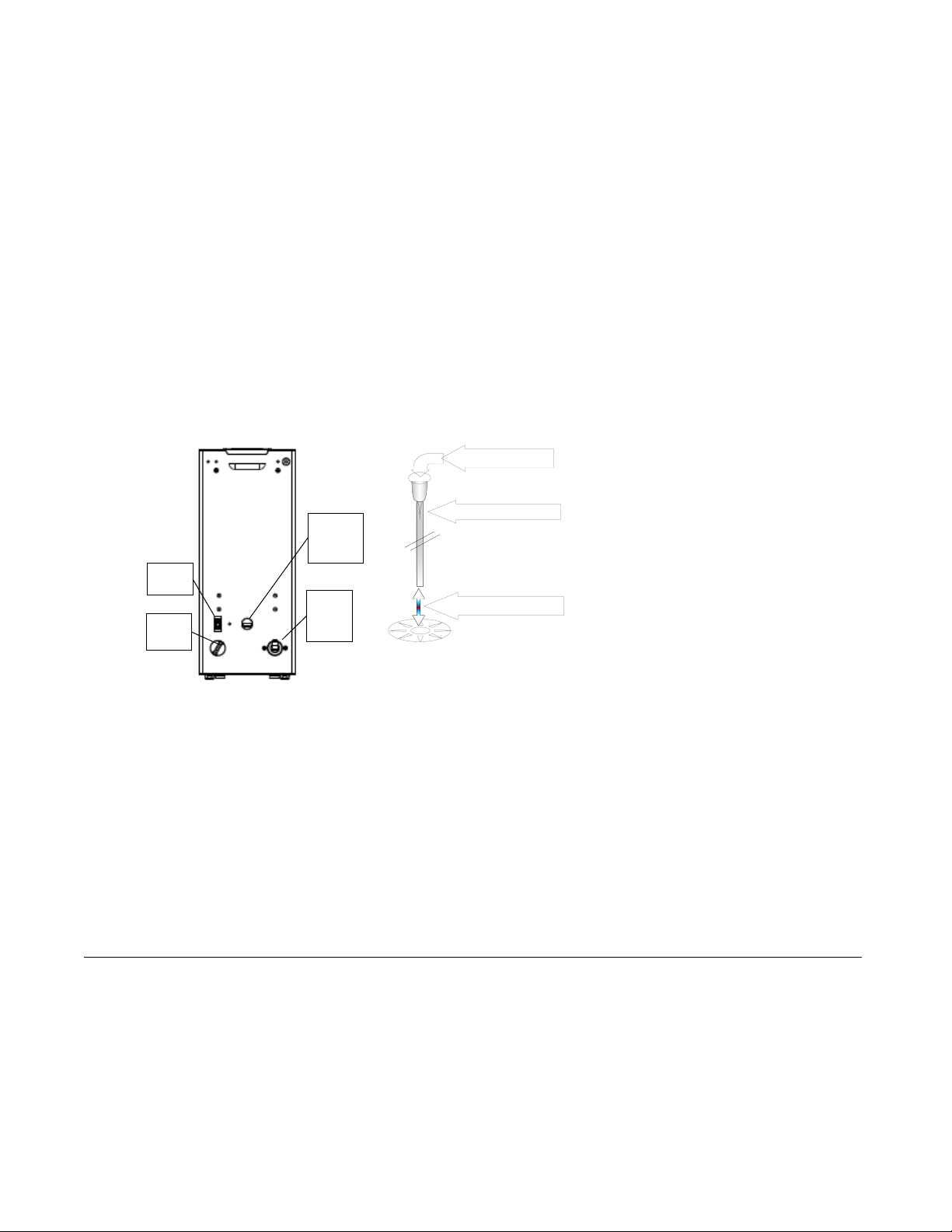
3. Turn on the power switch, located in the back of the unit.
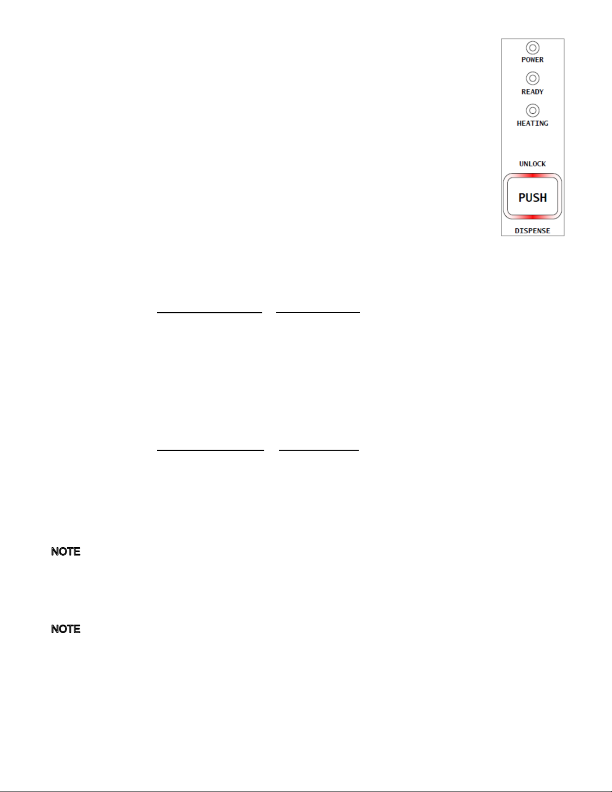
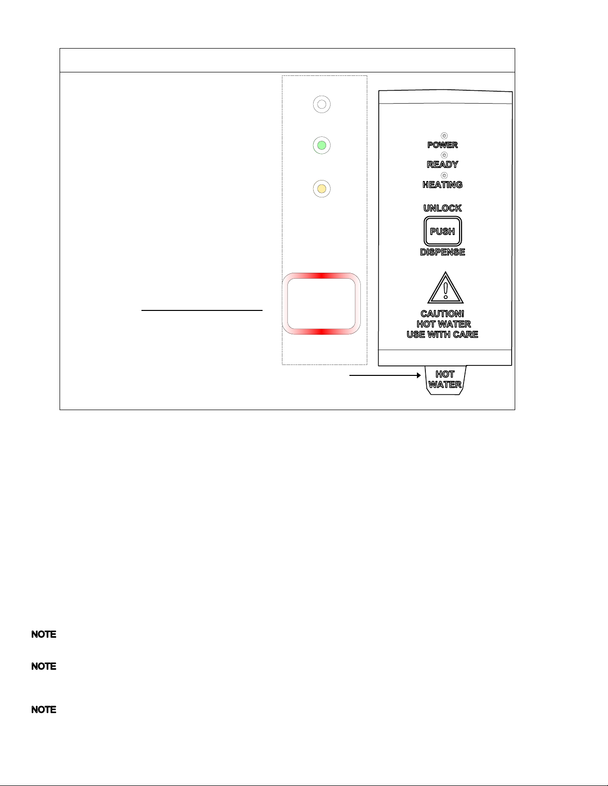
4. The LED indicator lights will show “Heating” (see illustration Page 4) on start-up
5. The hot water tank will begin filling and will stop when the water is sensed by the probe at the top of the tank.
The heaters are disabled by the control board until the tank is full. Unit may need to be restarted during first fill.
6. The temperature and water tank fill level are pre-set at the factory. There is no need to turn off the heaters
during the installation process. The heaters are disabled by the control board until the tank is full of water. The
heating process will start automatically when the tank has filled.
7. Heaters will turn on when covered by water. Touch Panel displays status while the water is heating—there is no
“Filling” light. After the water has reached the set temperature, the “ready” icon will turn on.
8. Inspect for leaks. Look closely in the top and beneath the equipment and check all fittings during this inspection.
Operator Training
Review the operating procedures with the equipment operators. Pay attention to the following areas:
1. Show the location and operation of the water shut off valve as well as the circuit breaker for the unit.
2. We recommend leaving the power to the equipment on overnight. The water tank is well insulated and will use
very little electricity to keep the tank hot. Leaving the equipment in the “on” position will also avoid delays at the
beginning of shifts for the hot water dispenser to reach operating temperature.
Standby heat loss is ≤100 watts per hour.
Installation safety and hygiene directions-For International and CE equipment
1. Access to the service area is restricted to persons having safety/hygiene knowledge and practical experience of
the coffee brewer. This appliance must be installed in locations where it can be overseen by trained personnel.
2. For proper operation, this appliance must be installed indoors where the temperature is between 10°C/50°F to
35°C/95°F. Drain and remove al liquid from equipment and lines if exposed to freezing temperatures.
3. All commercial cooking equipment, including this unit, is not intended for use by children or persons with
reduced physical, sensory, or mental capabilities. Ensure proper supervision of children and keep them away
from the unit.
4. Children should be supervised to ensure that they do not play hot beverage equipment.
5. This unit must be installed and serviced by qualified personnel only.
6. Installation must conform to all local electrical and plumbing codes. Installation by unqualified personnel will void
the unit warranty and may lead to electric shock or burn, as well as damage to unit and/or its surroundings.
7. If the power cord requires repair or replacement-it must be performed by the manufacturer or authorized service
personnel with the specified cord only from the manufacturer in order to avoid a hazard.
8. Review the dimensions for the unit and verify that it will fit properly in the space intended for it. Verify that the
counter or table will support the total weight of the filled brewer and dispensers (See: Technical Data Page 2).
9. Place the brewer on the counter or stand. When the brewer is in position, level it front to back as well as side-to-
side by adjusting the legs.
10. Do not tilt appliance more than 10° to insure safe operation.
11. Unit is for protected indoor use only. Do not steam clean or use excessive water on unit.
12. This unit is not “jet-proof” construction. Do not pressure wash or use jet spray to clean this unit.
13. The unit is not waterproof-do not submerge or saturate with water.
Do not operate if unit has been submerged or saturated with water.
Equipment exposed to flood and contaminated must not be used due to electrical and food safety.
1401.000049.00
1101.000210.00
1104.000103.00

Go to fetco.com for the latest version of all information P119 User Guide HWD-2102 REVISED MARCH 2020
11
Parts Diagrams
Drawing 1104.00150.00 TANK ASSEMBLY, HWD-2102
REF
QTY
Part Number
NAME
1
1
1114.00149.00
TANK WELDMENT, HWD-2102, GROMMET DESIGN
1
1
1107.00014.00
HEATER ASSEMBLY, IMMERSION 1440W/120VAC
1
1
1107.00008.00
HEATER ASSEMBLY, IMMERSION 2100W/120VAC
2
1
1107.00015.00
HEATER ASSEMBLY IMMERSION, 3200W/240VAC
3
1
1003.00109.00
BRACKET, HEAT SINK
4
1
1059.00001.00
TRIAC 40A, 600V
5
4
1083.00009.00
WASHER, #6 SCREW , INTL TOOTH LOCKWASHER
6
4
1084.00010.00
NUT, HEX, #6-32, UNDERSIZED, ZINC PLATED
7
1
1051.00016.00
BOARD, TRIAC DRIVE WITH RC FILTER
8
1
1023.00166.00
FITTING, COLD WATER INLET, GROMMET DESIGN
9
3
1024.00050.00
GROMMET, SILICONE, 11.4mm ID
10
1
1023.00167.00
FITTING, BREW, GROMMET DESIGN
11
2
1024.00053.00
LEVEL AND TEMP PROBE GROMMET
12
1
1112.00002.00
PROBE WELDMENT, WATER LEVEL 2.25" LG
13
1
54026
PROBE, TEMPERATURE 5" LONG, 50k
14
1
1023.00183.00
FITTING, DILUTION, TBS-2121
15
1
1003.00005.00
BRACKET, ONE SHOT THERMOSTAT
16
1
1053.00004.00
THERMOSTAT, SINGLE SHOT, 25A
17
1
1024.00007.00
O-RING, DASH #344, TANK COVER
18
1
1102.00007.00
TANK COVER ASSEMBLY
19
1
1044.00004.00
LABEL, DANGER, HIGH VOLTAGE

Go to fetco.com for the latest version of all information P119 User Guide HWD-2102 REVISED MARCH 2020
12

Go to fetco.com for the latest version of all information P119 User Guide HWD-2102 REVISED MARCH 2020
13
REF
QTY
Part Number
NAME Parts Breakdown HWD-2102, Drawing 1101.00290.00
1
1
1111.00028.00
BODY, WELDMENT, HWD-2102
2
1
1086.00020.00
BUSHING, STRAIN RELIEF, .425"-.475" DIA CABLE
3
1
1058.00020.00
SWITCH, PWR ROCKER RED, ILLUM. 250VAC
4
1
1023.00147.00
PLUG, TANK SERVICE DRAIN FOR 18 GA AND UP BODY
5
1
1057.00059.00
VALVE, 0.66 GPM BRN FLOW REG, 180DEG/24VDC
6
2
1082.00010.00
SCREW, PAN HD. PHIL. MACH., M4x10 ZINC-PLATED
7
1
1102.00164.00
ADAPTER ASSY, 3/4" BSP X 1/4 SAE FLARE
8
1
1102.00159.00
POWER SUPPLY ASSEMBLY, HWD-2100
9
4
1083.00011.00
WASHER, #8 SCREW SIZE, INTERNAL TOOTH LOCK
10
4
1084.00006.00
NUT, 8-32 18-8 HEX MACHINE SCREW
11
1
1102.00179.00
DISPENSE VALVE ASSEMBLY, HWD-2102
12
4
1082.00023.00
SCREW, #8-32 X 3/8 TRUSS HD PHIL., MACHINE
13
4
1083.00010.00
WASHER, #10 SCREW W/NEOPRENE-BONDED SEAL
14
4
1029.00020.00
SPACER, RND. UNTREADED, #6 SCREW SIZE, 1/4" OD X 1"LG.
15
1
1108.00021.00
BOARD ASS'Y., SOFTWARE, HWD-2102 EXPORT
16
4
1029.00018.00
NUT, #6 KNURLED THUMB
17
1
1104.00150.00
TANK ASS'Y., HWD-2102, 1440W/120VAC
17
1
1104.00151.00
TANK ASS'Y., HWD-2102, 2100W/120VAC
17
1
1104.00148.00
TANK ASS'Y., HWD-2102, 3200W/240VAC
18
1
1112.00115.00
BRACKET WELDMENT, TANK LOCK, HWD-2100
19
1
1029.00002.00
FITTING, HOSE BARB TEE, SIZE 3/8"
20
6
1086.00003.00
UNICLAMP, 15.9 HOSE OD CLAMP
21
1
1029.00017.00
FAUCET, SILICONE, HWD-2100
22
1
1023.00153.00
TOP COVER, HWD-2102
23
1
1102.00250.00
ASSEMBLY FRONT PANEL, MEMBRANE SWITCH, HWD-2102
24
1
1023.00154.00
BOTTOM BASE, HWD-2102
25
1
1023.00152.00
FRONT PANEL BOTTOM, HWD-2102
26
4
1023.00136.00
LEG, HWD-2100
27
1
1102.00156.00
DRIP TRAY ASSEMBLY, HWD-2100
28
1
1024.00041.00
PUSH IN GROMMET, 1/4"ID (7/16" PANEL HOLE)
29
10
1082.00058.00
SCREW, # 8-32 X 5/8, FLAT HD, PH, 18-8 SS
30
2
1084.00027.00
NUT, CLIP ON (J-NUT), #8-32, 18-16 GA., BPF
31
1
1402.00071.00
HARNESS, UNIVERSAL RETROFIT, HWD-2102
32
1
1025.00039.00
TUBE, 5/8" OD X 3/8 ID X 10" LG, DRAIN
33
1
1025.00040.00
TUBE, 1/4" OD X .125" ID X 16" LG, VENT
34
1
1025.00017.04
TUBE, SILICONE, 3/4" OD X 1/2" ID X 3.00" LG, DISPENSE
35
1
1025.00042.00
TUBE, 5/8" OD X 3/8" ID X 2" LG, BOTTOM TANK
36
1
1025.00046.00
TUBE, 5/8" OD X 3/8" ID X 5.0" LG, DOUBLE VALVE
37
1
1063.00016.00
POWER CORD, 120VAC W/NEMA 5-15P PLUG
37
1
1063.00015.00
POWER CORD, 120 VAC, 12/3 AWG ,20 AMP , W/5-20P NEMA PLUG
37
1
1063.00032.00
POWER CORD,, NEMA 6-15P, 15A/250V, W/O TERMINALS
38
1
1029.00023.00
FITTING, SINGLE BARBED ELBOW, 1/4", KYNAR
39
2
1083.00005.00
WASHER, M4 18-8 SS, INT. TOOTH LOCKWASHER
40
2
1086.00002.00
CLAMP, HOSE, SIZE "G" NYLON
41
1
1044.00001.00
LABEL "FOR USE ON IND. CIRCUIT"
42
4
1029.00025.00
FOOT, ANTI-SLIP, 0.60" DIA DISC
43
1
1023.00155.00
PLUG, BOTTOM BASE, HWD-2100
44
1
1082.00091.00
SCREW #8-32 X 1.75" FLAT HD PH, MACHINE
45
2
1064.00004.00
WIRE CONNECTOR, SCREW ON, MODEL 74B, YELLOW
46
1
1025.00045.00
TUBE, 5/16" OD X 3/16" ID X 2.5" LG, PROP VALVE
47
1
1046.00035.00
LABEL, WARNING "TO REDUCE RISK OF ELECTRIC SHOCK OR FIRE"

Go to fetco.com for the latest version of all information P119 User Guide HWD-2102 REVISED MARCH 2020
14
Wiring Diagram
Other manuals for HWD-2102
1
Table of contents
Other Fetco Dispenser manuals

Fetco
Fetco XTS Series User manual

Fetco
Fetco HWD-2110 TOD User manual

Fetco
Fetco CBS-2031ee User manual

Fetco
Fetco LUXUS LGD-10 Specifications

Fetco
Fetco L3D-10 Operating instructions

Fetco
Fetco L3D-10 User manual

Fetco
Fetco L3D Series User manual

Fetco
Fetco HWD-2105 TOD User manual

Fetco
Fetco HWB-2 User manual

Fetco
Fetco HWB-2 User manual