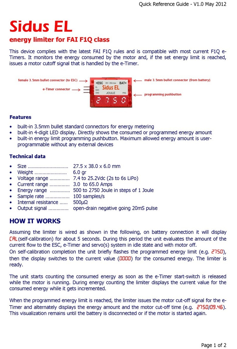
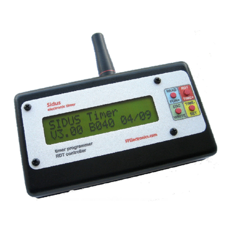
ffelectronics Sidus F1C User manual

Sidus
SidusSidus
Sidus F1C
F1C F1C
F1C
FAI Free Flight Electronic Timer
Operating Manual
Version 4.0 - Jun 2010 - © M.U. 2007/2010

Sidus - electronic timer
2/11
Preface
The system herein described replaces a clockwork timer by recreating the disc rotation
through a micro servo. The movement is controlled by a tiny electronic board, installed on
the model, which holds the programmed timing sequence and all the information needed
for the disc positioning. The disc rotates of one step and releases an arm when the time
for a programmed function expires. Although the micro servo has top ball bearing and
carbon gear, it has not to support the strain of the arms as the disc is separately pivoted to
the faceplate. Only one pushbutton (i.e. the start switch) is used to set, start, stop and
reset the timing. A pocket size programmer with only 4 keys and a large LCD display, is
used to read or change the timing and dethermalize the model (RDT). It also allows
accurate adjustment of the micro servo positioning. The devices communicate through an
optical link, therefore no cables are needed. A long range radio link used for the RDT.
Getting started
Refer to the pictures of next page to recognize the system components
•Connect the Timer control board
1
to the battery
2
and to the micro servo by
matching the color of plugs and cables. The Timer comes with a pre-programmed
timing sequence of 1 sec. for the first 5 functions and 10 sec. for the DT that can be
easily changed as described later. If idle for over 120 seconds the control board will
turn to a “sleep” state (leds OFF). It will wake up by shortly pressing the start switch
•Locate the Hall sensor
3
at the end of the longest cable on the control board
1
.
Insert the sensor fully inside the radial hole on the bottom of the magnetic start switch
2
as shown in
4
. Later the sensor will have to be permanently glued to the start
switch as detailed in the Installation Notes
•The Programmer
5
must be switched on: remove the slide cover on the bottom of the
case and move to ON the slide microswitch placed in the battery compartment. Also
the Programmer will go to sleep if idle for over 120 seconds. It will wake up by shortly
pressing one of the keys
•The LiPo Charger
6
comes with bare wires by the 12V side to allow the connection of
a proper plug depending on the power source used to charge the battery packs.

Sidus - electronic timer
3/11
System components
IR sensor Red & Green leds
RDT antenna
socket
“SE”
MECHANICAL ASSEMBLY O TION
Timer Control Board
Timer Battery
M
AGNETIC
S
TART
S
WITCH
Hall Sensor
BOTTOM
VIEW
Servo
Battery
Hall sensor
Charger
ROGRAMMER
IR sensor
aperture
LCD display
RDT tx antenna
keyboard
lug
L
I
O
C
HARGER
9
-
12Vdc
“VE”
MECHANICAL ASSEMBLY O TION

Sidus - electronic timer
4/11
Timer
Duration and resolution of the functions
Each of the 6 available functions (F1 to F6) has a programmable time interval. The range
for F1 and F2 is 0.01 to 9.99 sec. The range for F3 to F5 is 0.1 to 99.9 sec. and the range
for F6 (DT) is 1 to 720 sec.
The intervals programmed for the first 5 functions sum up to each other. For
convenience the interval for F6 (DT), is referred instead to the start of the Timer. It
follows that the minimum interval for the DT will match the sum of the previous 5
functions rounded in excess to the integer second.
States of the Timer
Like a clockwork timer, this Timer goes across different predefined states. The pair of
colored leds on be Timer board shows the current state of the Timer according to the
following scheme:
1. RED ON: Timer charged – disc at the beginning of its travel
2. GREEN ON: Timer discharged – disc at the end of its travel
3. Flashing RED (fast): Timer armed, the timing sequence will start at start switch
release
4. Flashing RED (slow): timing sequence in progress
5. Flashing GREEN: disc repositioning in progress
6. Flashing RED and GREEN (3 flashes): Timer battery pack to be recharged
Using the Timer
The function of the start switch depends on the current state of the Timer. Starting from a
discharged Timer (GREEN led ON, disc at end of its travel) the functions are:
•Resetting the Timer - bring down all the arms, press the start switch until the GREEN
led starts flashing, and then release it. The disc quickly turns back in steps to the
beginning of its travel and the RED led turns ON
•Starting the Timer - press the start switch until the RED led starts flashing fast. The
Timer is armed and the timing sequence will start as soon as the start switch is
released. During timing the RED led flashes slow and the disc rotates of one step to
release an arm at the end of each programmed function until it reaches the end of its
travel and the Timer turns off
The timing sequence can be early terminated by pressing the start switch: all the
pending functions are executed in steps and the disc returns to the end of its travel
Automatic switch off and Timer battery check
When the Timer goes to sleep to save power, its state and all the internal data are
retained. When it wakes up, if battery voltage is found insufficient, it flashes both the leds
(three times) and goes back to “sleep” to prevent the batteries from being harmed.

Sidus - electronic timer
5/11
T1
T2
T3
T4
Programmer
T1, T2, T3, T4 keyboard
Through these 4 keys it is possible to read, modify, rewrite the timing sequence and
dethermalize the model. It is also possible to change the default settings and accurately
adjust the micro servo positioning. The function of each key depends on the state of the
Programmer and if it is pressed for a short or long time.
Automatic switch off and Programmer battery check
The Programmer goes to sleep if idle for about 120 sec. and wakes up by pressing one of
the keys. If the data have not been transferred to the Timer they will be lost. If the voltage
is insufficient, the Programmer displays
“
Battery low!
”
and goes back to sleep to prevent
the batteries from being harmed.
Notes about Programmer’s key pressing
The Programmer has only 4 keys. A long key pressure (press and hold) or a short
key pressure (press and release) may be required, depending on the situations and
according to the following rule: choices displayed in upper case (e.g. READ,
WRITE,..) require a long pressure, choices displayed in lower case (e.g. Servo,..) require
a short pressure
Notes about Programmer ↔Timer IR communication
The Programmer and the Timer communicate over an optical link. When using the
Programmer make sure to:
1. check that the Timer is ON (RED or GREEN led ON), if not just turn it back on by
shortly pressing the start switch
2. keep the Timer and the Programmer with the IR sensors mutually visible (distance
shorter than 20 cm)

Sidus - electronic timer
6/11
T1 T3
T2 T4
Programming the Timer
The Programmer displays the possible choices by displacing them at the corners of a
rectangle: each choice is selected by pressing the key that corresponds to the same
corner in the rectangle made up of the 4 keys (see drawing below). When possible, the
same method is used for all the menus shown on the display.
Modify the timing sequence
After power on, the Programmer display shows the following:
Before modifying the timing sequence it is needed to read it from the Timer. Press T1
(Read) until the intervals programmed for the 6 functions appear on the display:
F1 F2 F3
F4 F5 F6
By shortly pressing T1 now, an asterisk appears close to the time of the first function (F1).
Shortly press again T1 to move the asterisk close to the function that must be modified,
then keep T1 pressed until the asterisk turns into ‘w’ (write) and release it: the function is
ready to be modified. Shortly press T3/T4 to increase/decrease the time of one step or
keep T3/T4 pressed to have faster increments/decrements. When the wished value is
reached, shortly press T2 (Esc) to end modifications or shortly press again T1 to choose
another function to modify. The modified values shown on the display must now be written
onto the Timer for permanent storing. Keep T2 (write) pressed until the following message
appears:
The modified values are then read back from the Timer and shown again on the display.
Writing
WritingWriting
Writing
1.00 1.00 01.0
1.00 1.00 01.01.00 1.00 01.0
1.00 1.00 01.0
01.0 01.0 0010
01.0 01.0 001001.0 01.0 0010
01.0 01.0 0010
READ RDT
READ RDTREAD RDT
READ RDT
WRITE SET
WRITE SETWRITE SET
WRITE SET
READ RDT
READ RDTREAD RDT
READ RDT
WRITE SET
WRITE SETWRITE SET
WRITE SET

Sidus - electronic timer
7/11
JUMP2
JUMP2 JUMP2
JUMP2
Exit
Exit Exit
Exit Servo
ServoServo
Servo
SET menu
Remote dethermalization (RDT)
The model can be dethermalized by keeping T3 (RDT) pressed until the display shows the
following message:
The Timer will terminate the sequence by executing the remaining steps until the disc
reaches the end of its travel.
Note: it is possible to program RDT to just stop the engine at first activation. Please
see the following for the details.
Advanced settings
From the MAIN menu enter the SET menu by pressing T4 (SET) for over 3 seconds:
Disc positioning modification
The Programmer allows changing the positions assumed by the disc for each function.
1. Press and release T4 (Servo) to enter the FUNCTION menu. The disc moves to the
start position
2. Press T3 (func+) or T4 (func-) to increase or decrease the current function and step
the disc to the related position. The disc steps to 7 different positions (START →
FUNC1 →FUNC2 →FUNC3 →FUNC4 →FUNC5 →DT). By convention, START
and DT correspond to the initial and final disc position respectively.
3. By T3 or T4 reach the wished function (e.g. FUNC5), then press T1 until the
POSITION menu is displayed:
START
START START
START f
ff
func+
unc+unc+
unc+
Exit
Exit Exit
Exit f
ff
func
uncunc
unc-
--
-
FUNCTION menu
READ
READ READ
READ
RDT
RDT RDT
RDT
WRITE
WRITEWRITE
WRITE
SET
SET SET
SET
MAIN menu
RDT
RDTRDT
RDT
Tr nsmitting
Tr nsmittingTr nsmitting
Tr nsmitting…

Sidus - electronic timer
8/11
JUMP2
JUMP2 JUMP2
JUMP2
Exit
Exit Exit
Exit Servo
ServoServo
Servo
SET menu
Writing
WritingWriting
Writing…
4. Press and release T3 (pos+) or T4 (pos-) to accurately adjust the disc position for the
current function (Keep T3 or T4 pressed to have a continuous movement). The new
positions are permanently stored
5. Press T2 (Exit) to go back to the FUNCTION menu and repeat the steps 3. and 4. to
adjust the disc position related to another function or press again T2 (ESC) go back to
the SET menu.
Engine stop programming in case of early radio DT
If the RDT is activated while the engine is running the disc will jump to an intermediate
position (safer than DT) in order to prevent model damage due to the high speed it has
probably reached. If the RDT is activated again, or if it is activated when the engine is not
running, the disc will immediately jump to DT.
1. Through the FUNCTION menu (see “Disc positioning modification”) move the disc
to the function the disc must jump to (JUMP2) in case of early DT
2. Press and release T2 (Exit) to exit the FUNCTION menu and enter the SET menu:
3. Keep T3 (JUMP2) pressed until getting the following message
Check the settings this way: start the timer, push the RDT button once during the
function(s) before engine stop and check that the disc jumps to the programmed function.
Push the RDT button again and check that the discs jumps to DT (end of travel)
FUNC5 pos+
FUNC5 pos+FUNC5 pos+
FUNC5 pos+
Exit
Exit Exit
Exit pos
pos pos
pos-
--
-
POSITION menu

Sidus - electronic timer
9/11
Charging the batteries
A micro LiPo battery Charger is supplied with the system. The red / black cable must be
connected to any 9-12 Vdc power source (e.g. to the car lighter socket). The same
Charger is used to charge both the Timer and the Programmer LiPo batteries separately.
Full recharge of a battery will take about 2 hours.
Use only the battery charger supplied with the system. Discard a LiPo battery if it
shows bulges or scratches. Never leave a LiPo battery unattended while charging.
Charge must take place in a safe place and always far from flammable materials.
Status of the charger leds
•Green ON, Red ON : 9-12Vdc power connected, no LiPo battery connected:
•Red ON, Green OFF : Charge in progress
•Red OFF, Green ON : Charge complete
Charging the Timer battery
Connect the charger 3-pin plug to the Timer recharge cable of the control board
through the adapter cable supplied: the battery can remain connected to the Timer. A
spare battery can be directly connected to the 2-pin socket on the charger through the
other supplied adapter cable.
Charging the Programmer battery
Connect the charger 3-pin plug to the Programmer recharge
socket, accessible by removing the slide cover on the bottom of the
case. The internal battery remains always connected to the
Programmer.
Disconnecting the battery packs
If the system is not going to be used for a long time, it is a good rule to disconnect the
Timer battery pack and switch off the Programmer through its microswitch.
Wiring
For the connections just match the colors of the plugs and cables, however the connectors
are polarized and do not allow reversed insertion:
•RED : BATTERY / CHARGER
•BLUE or BLACK : MICROSERVO
the Timer control board recharge plug remains normally unconnected except
during recharge of the battery as described above.
recharge socket
ON-OFF switch

Sidus - electronic timer
10/11
Installation notes
Hall sensor
Insert the sensor in the hole located in the bottom of the magnetic
start switch as shown in the picture. Do not put it upside down.
Glue it to the start switch with silicon sealant or epoxy.
Should it be necessary to extract the plug at the other end of the sensor cable, do
not pull it through the wire. The connector plug has small protruding edges that
must be grabbed with tweezers (or with the finger nails) to gently pull the plug out
of the socket
Control board
Place the control board with the IR sensor and the leds close to the front-end side
to have them clearly visible through a small clear plastic transparent window. All
wires and connectors must be laid in a clean way with no mechanical tension.
Avoid firm fastening of the Timer control board to the fuselage. Use foam rubber in order
to minimize possible malfunction caused by high frequency vibrations.
Battery and recharge connector
Provide easy access to the battery pack and to the recharge connector anytime to
disconnect or recharge the battery when needed. The battery pack ensures about
80 flights of 180 seconds each. Do not recharge it too frequently, just refresh it
from one flight session to another. If you are not going to fly the model in a few weeks it is
recommended to disconnect the battery pack.
Mechanical assembly
For the “SE” type assembly use a thin rubber gasket under the faceplate to fasten
the mechanical assembly to the fuselage. It is also recommended to use a rubber
gasket (O-ring) between the faceplate and the bottom of the head of the fastening
screws. For the “VE” type assembly refer to the specific instructions.
RDT antenna
Fasten a 175 mm. long (0.4 - 0.5 mm diameter) steel wire vertically to the top of the
fuselage: this will be the RDT antenna. It must be electrically insulated from carbon or
conductive parts through a Teflon or Nylon spacer. Inside the front-end, connect/solder
the antenna to the flexible cable supplied and solder the other end of this cable to the
RDT antenna plug, also supplied. Plug this cable to the RDT socket on the mother board
(see picture
1
). Failure to follow the above will result in a poor range of the whole RDT
system.
Note that when testing the RDT system on the bench, it may be needed to move
the Programmer a few meters away to operate correctly.

Sidus - electronic timer
11/11
Recommendations
Launch procedure
•Bring all the arms down, then push the start button to reset the Timer. The disc turns
back, then the red light turns ON. While the model is being prepared for launching the
RED led will go off (sleep after 120 sec. of inactivity) however the state of the Timer is
retained
•Prepare the model, check it, set it up, start the engine
•When ready to launch, press the start button and keep it pressed until the red light
starts flashing fast (after about 0.75 seconds). Make sure that the red light flashes fast
before releasing the model. The timing sequence starts when the start button is
released
Early termination of the timing sequence
After the timing sequence has started, it can be terminated in any moment by pressing the
start button: all the arms will be quickly released in turn.
Dethermalization
The effect is the same as the termination procedure. Be aware that this command
is accepted also during climb. On the Programmer press and keep pressed the red
button to dethermalize the model.
Important notes about the micro servo
When the Timer mechanics is originally assembled, the micro servo is thoroughly
centered and fastened to the faceplate to ensure the correct alignment of the ball
race. Be aware that if the micro servo is unscrewed from the faceplate the original
positioning and the correct alignment are lost. It is not recommended to unscrew the micro
servo: if you do that, it will be at your risk. Should any intervention on the micro servo be
necessary for any reasons (cleaning, replacing,...) it is strongly recommended to return the
whole mechanical assembly along with the control board. Incorrect repositioning of the
micro servo is likely to create extra friction in the rotation that may dangerously decrease
the torque available on the disc with consequent possible failure in releasing the levers
Table of contents
Other ffelectronics Timer manuals

