FIAMA P50 Guide

MTP_
Data: 13/01/16 file: MTP_ing.doc pag 1/5
USER’S MANUAL AND MAINTENANCE
TRANSDUCER MTP_
MAGNETIC STRIP P50
MAGNETIC RING DM_

MTP_
Data: 13/01/16 file: MTP_ing.doc pag 2/5
Manual purpose
This manual has been designed by the manufacturer to provide the necessary information regarding the
instrument MTP_ to those who are authorized to carry out safely its installation, maintenance, dismantling
and disposal. All the necessary information for the buyers and planners can be found in the Sales catalogue.
Other than adopting good technical construction methods, the information should be read carefully and
strictly applied. Inobservance of this information could cause risks for the health and safety of people and
economical damage. This information, provided by the Manufacturer in the original language(Italian) is also
available in other languages to satisfy legislative and/or commercial needs. This manual must be kept in good
conditions by a responsible person in an ideal place so that it is always available for consultation. In case this
manual is lost or deteriorates, a replacement should be requested directly from the manufacturer quoting the
manual’s code. This manual reflects the state of skill of the instrument at the time of input on the market:
however the manufacturer reserves the right to make changes, add or improve the manual without giving any
reason to hold the present manual inadequate.
Identification of the equipment
The identification plate represented is applied on the instrument.
To find out the identification code of the instrument, consult the sales catalogue.
Environmental conditions
Temperature setting: min. 0°C, max. + 50°C.
It is forbidden to use the instrument other than its specific use and in potentially explosive conditions or where
anti- explosive elements are used.
Storage
Here below are some references to be followed for the storage of the instrument.
Avoid environments with excessive humidity and those exposed to bad weather (avoid open areas). Avoid
putting the instrument directly on the ground. Store the instrument in its original packing.
Conformity declaration and EC marking
The instrument answers to the following Communitarian Directives:
2014/30/EU Electromagnetic compatibility, 2011/65/EU RoHS.
Maintenance
The instrument does not needs a particular maintenance except cleaning to do only with a soft cloth dampen
with ethylic alcohol or water. Do not use hydrocarbon solvents (petrol, diluents, etc.): the using of these
products could affect the proper functioning of the instrument.
Reparations should be done only and exclusively at the FIAMA technical assistance centre.
Calibrations and tests
It is advisable to verify the transducer calibration periodically, once every working year.
Assistance request procedure
For any kind of technical assistance request, contact the sales department of the Manufacturer directly
indicating the information given on the identification plate, the number of hours used and the type of defect.
Manufacturer’s responsibility
The manufacturer declines any responsibility in case of :
• Using the instrument contrary to the national safety and accident-prevention laws.
• Wrong installation, inobservance or wrong procedures of the instructions provided in the present manual.
• Defective electrical power supply.
• Modifications or tampering.
• Operations carried out by untrained or unqualified staff.
The safety of the instrument also depends on the strict observance of the procedures indicated in the
manual: always operate the instrument in its functioning capacity and carry out a careful routine maintenance.
• All phases of inspection and maintenance should be done by qualified staff.
• The configurations provided in the manual are the only ones permitted.
• Do not try to use it anyway contrary to the indications provided.
• The instructions in this manual do not substitute but accomplish the obligations of the current legislation
regarding the safety laws.
MTP_
Data: 13/01/16 file: MTP_ing.doc pag 3/5
Installation
Before installing the instrument, read the following warnings:
a) Connect the instrument strictly following the instructions of the manual.
b) It is the responsibility of the user to check, before using, the correct settings of the parameters of the
instrument to avoid damage to persons or things.
c) The instrument CANNOT function in a dangerous environment (inflammable or explosive).
Description
The transducer MTP combined with the magnetic strip P50 is an incremental measure system without
contact for linear distances. The measure transducer integrates in the same device, a sensor sensitive to a
magnetic field, an electronic signals conversion circuit, and an output circuit. The sensor running on the
magnetic strip produces a signal which, opportunely amplified and worked out, is changed into an
incremental position signal for interfacing with displays, PLC, CNC, axes control, etc.
The band consists of a magnetized plastic ferrite strip with alternate magnetic poles of 5 mm pitch, carried by
a ferromagnetic steel strip. Mechanical protection of the plastic ferrite strip is supplied by a nonmagnetic
steel strip. The capacity to meausure distances longer than a meter, easy assembling, absence of parts that
contact/rub, a waterproof transducer and a water-oil-dust-shaving resistant strip make this system suitable
for a large number of applications, while taking position measurements of machinery within industries such
as: woodworking, glass, marble, etc…
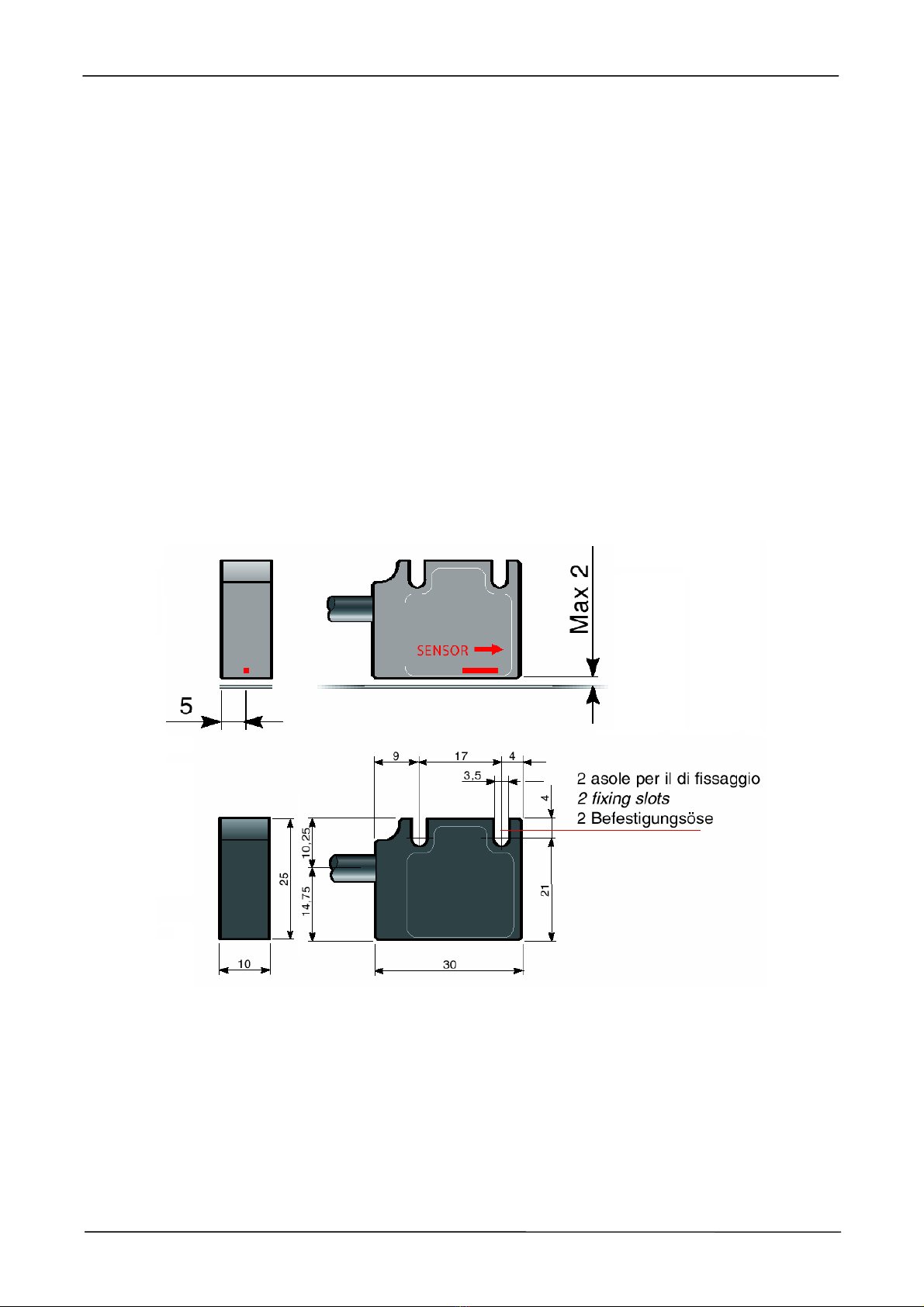
Transducer mounting
For the optimal operating of the system the magnetic sensor, is necessary to observe the quotas mounting
on the following draws, pay attention that the distance between the sensor and the magnetic band doesn’ t
exceed 2 mm.
MAGNETIC STRIP

MTP_
Data: 13/01/16 file: MTP_ing.doc pag 4/5
Magnetic strip
The band consists of a magnetized plastic ferrite strip with alternate magnetic poles of 5 mm pitch, carried by
a ferromagnetic steel strip. Mechanical protection of the plastic ferrite strip is supplied by a non magnetic
steel strip with tickness 0,2mm.
The magnetic band is assembled by sticking it with a biadhesive tape. The surface has to be smooth, clean
and dry: is advisable to clean it with a degreasing product (isopropyl alcohol, ethyl alcohol, solvents, etc). The
magnetic band has to be sticked holding the plastic ferrite side in the direction of the sensor, which means
the steel side leaned on the stand surface. Fixed the magnetic band, to keep off damages due to abrasions
or grazes of the plasic ferrite strip, is advisable the appliance (always biadhesive) of the non magnetic
protection streep.
The optimal ambient temperature for stick the biadhesive tape is over 10°C. The maximum adherence of the
tape works out after 48 hours (about) of the application and is kept between –10 and 80°C.
Magnetic ring
1,7
non magnetic steel strip
(mechanical protection)
plastic ferrite strip
steel strip
(plastic ferrite support)
10
sensor side
MAX 2mm
MTP_
Data: 13/01/16 file: MTP_ing.doc pag 5/5
Connection scheme
Brown +10÷25VDC / 5VDC
Yellow signal A
Orange signal /A
White signal B
Geen GND
Shield internally not connecetd
Purple signal /B
LINE DRIVER TTL OUTPUT
(type: MTP2, MTP3, MTP4)
Gray signal Z
Black signal /Z
Brown +10÷25 VDC
Yellow signal A
White signal B
Gray signal Z
PUSH-PULL OUTPUT
(type: MTP1)
Geen GND
Shield internally not connecetd
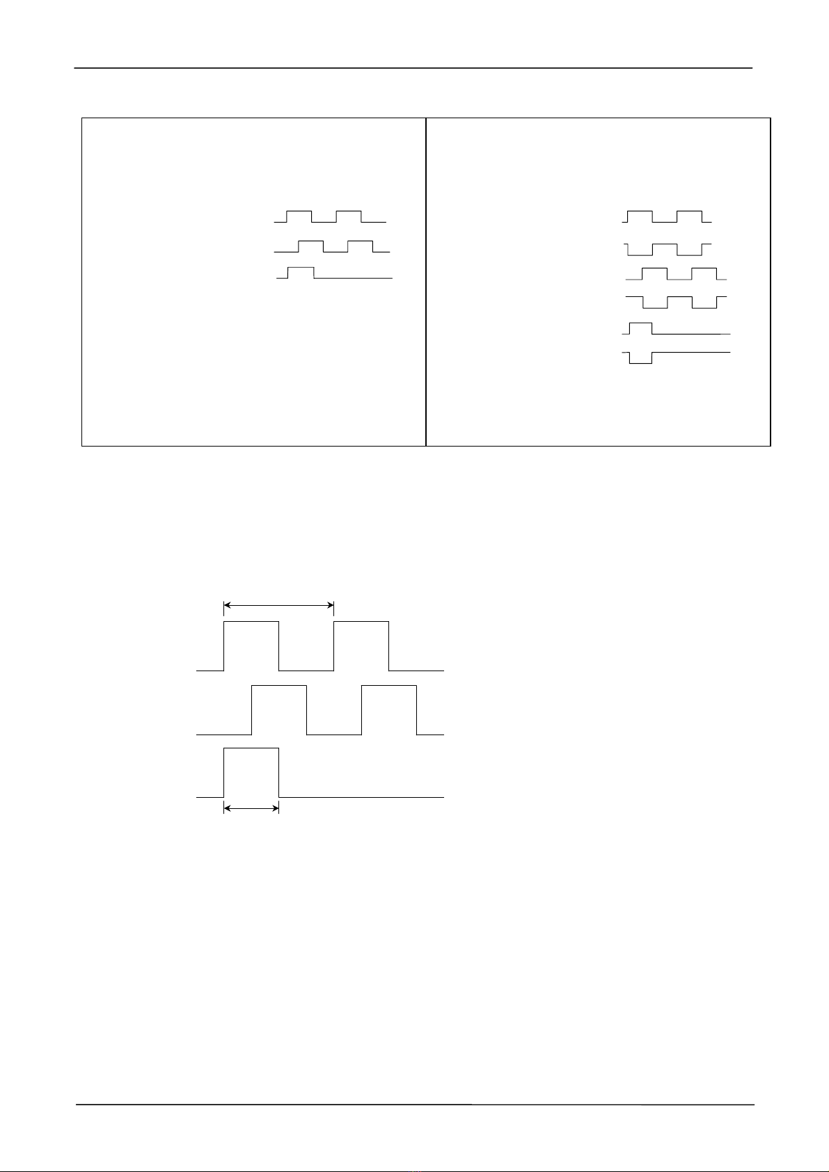
Output signals
The measure transducer turns the shifting compared to the magnetic band in digital signals with two squaring
channels (A, B) very similar to the signals produced by incremental encoders or optical lines. Every 5 mm you
have a reference impulse (Z) which can be used as the zero-setting signal of the quota. Pay attention: if the
reference signal Z isn’t used it has to be isolate electrically of the other signals and of the power supply.
0,04 mm
signal A
signal B
signal Z
0,02 mm periodic every 5 mm
RESOLUTION:
• 0,04mm x1 count
• 0,02mm x2 count
• 0,01mm x4 count

MTP_
Data: 13/01/16 file: MTP_ing.doc pag 6/5
MTP transducer specifications
Power supply 10-25 VDC±20%, max 50mA,
or 5VDC±5% max 100 mA
Signals output 2 quadrature channels,
reference pulse each 5mm
Output push-pull max 20mA, short-circuit protected
or TTL line driver 5V RS422 (to specify)
Resolution max 0,01 mm (x4 count)
Measure Accuracy 0,1 mm/m
Maximum speed 3 m/s
Electric connection cable output φ5 standard length 2m suitable for movable wiring
Maximum distance transducer/band 2 mm
Transducer dimensions 30 x 25 x 10 mm
Pretection degree IP65
Housing alluminium
Working temperature 0 ÷50°C
Electromagnetic compatibility 2014/30/EU
RoHS 2011/65/EU
Magnetic strip characteristics P50
Length on request, max 25m
Width 10 mm
Thickness 1,7 mm
Linear thermal expansion coefficient 11 ppm/K
Working temperature -10 ÷65°C
Magnetic ring characteristics DM30 - DM50
Ring external diameter DM30: Ø30,9 DM50: Ø48,7
Mounting hole DM30: Ø14 DM50: Ø20 (or Ø25)
Resolution with MTP_ transducer DM30: 2500 pulse/rev DM50: 3750 pulse/rev
Max rotation speed with MTP_ transducer 1500 RPM
Table of contents
Other FIAMA Transducer manuals

Popular Transducer manuals by other brands


Mianyang Weibo Electronic
Mianyang Weibo Electronic WB Series user manual

ProMinent
ProMinent Dulcometer DMT operating instructions

MKS
MKS MicroPirani 925 Series Short form manual

WIKA
WIKA WU-20 operating instructions

Alcatel Vacuum Technology
Alcatel Vacuum Technology BARATRON 622A instruction manual

Camille Bauer
Camille Bauer SIRAX CH-5610 operating instructions


