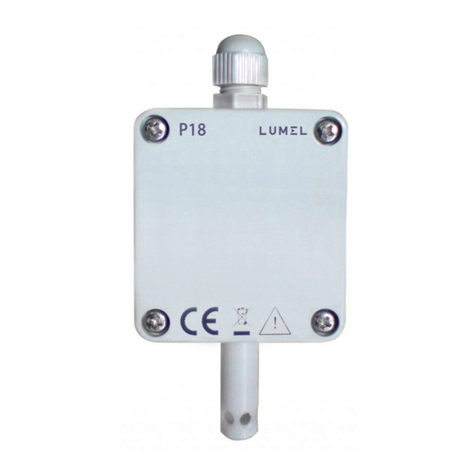
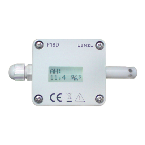
Lumel P18D User manual

PRZETWORNIK
TEMPERATURY I WILGOTNOŚCI
TEMPERATURE
AND HUMIDITY TRANSDUCER
P18(D)
INSTRUKCJA OBSŁUGI - SZYBKI START
Pełna wersja instrukcji dostępna na
Full version of user’s manual available at
www.lumel.com.pl
USER’S MANUAL - QUICK START PL
EN
Zeskanuj mnie
Zeskanuj kod Scan the code
AND HUMIDITY TRANSDUCER

2
2
PL
1. WYMAGANIA PODSTAWOWE,
BEZPIECZEŃSTWO UŻYTKOWANIA
W zakresie bezpieczeństwa użytkowania przetwornik odpo-
wiada wymaganiom normy PN-EN 61010-1.
2. MONTAŻ
2.1. Sposób mocowania
Przetwornik P18(D) mocowany jest na ścianie za pomocą połączenia śru-
bowego lub klejowego bez utraty klasy szczelności IP 65. Obudowa prze-
twornika jest wykonana z samogasnącego tworzywa sztucznego. Prze-
twornik ma złącza śrubowe umieszczone wewnątrz przetwornika, które
umożliwiają przyłączenie przewodów zewnętrznych o przekroju do 1 mm2.
Uwagi dotyczące bezpieczeństwa
• Montażu i instalacji połączeń elektrycznych powinna dokonać
osoba z uprawnieniami do montażu urządzeń elektrycznych.
• Przed włączeniem przetwornika należy sprawdzić poprawność
połączeń.
• Przetwornik jest przeznaczony do instalowania i używania
w przemysłowych elektromagnetycznych warunkach środowiskowych.
Rys. 1. Gabaryty przetwornika P18(D)

3
3
PL
2.2. Schematy podłączeń zewnętrznych
Patrz rysunek 3 i 4, strona 18.
Rys. 2. Rozmieszczenie otworów montażowych przetwornika P18(D)
3. OBSŁUGA
Przetwornik P18D wyposażony jest w pole odczytowe 8x2 znaki
z podświetleniem oraz jeden przycisk pojemnościowy umiejscowiony
na obudowie przetwornika. Przetwornik P18 nie jest wyposażony
w wyświetlacz ani w przycisk. Po podłączeniu przewodów, skręceniu
obudowy i włączeniu zasilania przetwornik jest gotowy do pracy z nasta-
wami fabrycznymi (tab. 4). Przetwornik może być programowany przez
interfejs RS-485. W przetworniku można programować następujące
parametry:
− parametry komunikacyjne,
− czas uśredniania pomiaru,
− charakterystyki indywidualne wyjść analogowych (dla wykonania
z wyjściami analogowymi).
W przetwornikach P18D istnieje możliwość programowania para-
metrów komunikacyjnych (adres, prędkość, tryb) za pomocą przycisku
pojemnościowego.
Istnieje możliwość połączenia przetwornika przez inne media transmisji
takie jak: ETHERNET, USB przy wykorzystaniu konwerterów produkcji
LUMEL S.A.

4
4
PL
3.1. Komunikaty po włączeniu zasilania przetwornika P18D
Po podłączeniu sygnałów zewnętrznych i włączeniu zasilania,
przetwornik wyświetla typ, aktualną wersję programu, numer seryjny
oraz ustawione parametry komunikacyjne (adres, prędkość transmisji
oraz tryb pracy).
Po około 5 sekundach przetwornik automatycznie przechodzi
do trybu pracy, w którym dokonuje pomiaru i przetwarzania na analo-
gowy sygnał wyjściowy. Wyświetla wartość mierzoną wraz z jednost-
ką na dolnym wierszu wyświetlacza, na górnym wierszu wyświetlacza
znajduje się informacja o typie wyświetlanej wielkości oraz piktogramy:
transmisji na łączu RS-485, trybu prezentacji wartości pomiarowej,
wskaźnika odczytu wartości mierzonej z czujnika oraz stanu pracy we-
wnętrznego grzejnika.
3.2. Opis pola odczytowego przetwornika P18D
Polem odczytowym w przetworniku P18D jest podświetlany
wyświetlacz znakowy LCD. Podświetlenie jest zapalane po włączeniu
zasilania oraz po naciśnięciu przycisku pojemnościowego na obudowie.
Podświetlenie jest automatycznie wyłączane po upływie czasu 30 sek.
bezczynności. Wskaźnik odczytu wartości
mierzonej z czujnika
Wskaźnik automatycznej prezen-
tacji wartości pomiarowych
Wskaźnik transmisji na łączu
RS485
Jednostka wielkości
wyświetlanej
Wartość wielkości
wyświetlanej
Typ wielkości wyświetlanej
Rys. 5. Opis pola odczytowego przetwornika P18D

5
5
PL
Opis symboli wyświetlanych przez przetwornik P18D znajduje się w tablicy 1.
Symbol Znaczenie
T: Typ wielkości wyświetlanej na dolnym wierszu LCD -
temperatura
RH: Typ wielkości wyświetlanej na dolnym wierszu LCD –
wilgotność względna
DP: Typ wielkości wyświetlanej na dolnym wierszu LCD –
punkt rosy
AH: Typ wielkości wyświetlanej na dolnym wierszu LCD –
wilgotność bezwzględna
Wskaźnik odczytu wartości mierzonej z czujnika
Automatyczny tryb prezentacji wyników pomiarów –
typ wartości wyświetlanej jest automatycznie
przełączany co 3 sekundy w kolejności: temperatura
→ wilgotność względna → punt rosy → wilgotność
bezwzględna → temperatura ….
Wskaźnik odbioru danych przez przetwornik P18D
na łączu RS-485
Wskaźnik wysłania danych przez przetwornik P18D
na łączu RS-485
hWskaźnik załączenia wewnętrznego grzejnika w celu
wysuszenia czujnika
3.3. Funkcje przycisku pojemnościowego przetwornika P18D
Przetworniki P18D zostały wyposażone w jeden przycisk
pojemnościowy umieszczony na obudowie. Położenie przycisku
ilustruje rys 6.
Rys. 6. Umiejscowienie
przycisku pojemnościowego
przetwornika P18D
Tablica 1

6
6
PL
Przycisk pojemnościowy służy do:
• załączenia podświetlenia wyświetlacza,
• zmiany trybu prezentacji wyników – przytrzymanie przycisku
przez około 2 sekundy powoduje przejście z trybu automatycznego
do trybu ręcznego prezentacji wyniku pomiarów lub odwrotnie
• zmiany typu wielkości wyświetlanej w trybie ręcznym prezentacji
wyniku pomiarów – krótkie dotknięcie przycisku powoduje zmianę
wielkości wyświetlanej.
• programowania parametrów komunikacyjnych (adres, prędkość,
tryb)
3.4. Menu programowania parametrów przetwornika P18D
Wejście w menu programowania odbywa się po naciśnięciu
i przytrzymaniu przycisku pojemnościowego przez czas ok. 5 sek.
Przy pierwszym wejściu w menu znacznik kierunku zmian zostanie
ustawiony na - zwiększanie wartości; kolejne wejścia w menu
spowodują cykliczne przełączanie kierunku zmian (2 wejście w menu
ustawi znacznik na v – zmniejszanie wartości). Jeżeli czas bezczyn-
ności przekroczy 20 sek. przetwornik wyjdzie z menu i przejdzie
do wyświetlania wartości mierzonych.
Rys. 7. Sposób wyświetlania informacji o parametrach transmisji
w menu przetwornika P18D

7
7
PL
Rys. 8. Algorytm programowania parametrów przetwornika P18D
4. DANE TECHNICZNE
Parametry podstawowe:
- zakres pomiaru wilgotności względnej (RH): 0...100%, bez kondensacji 1)
- błąd podstawowy przetwarzania wilgotności: ± 2% zakresu dla RH = 10...90%
± 3% w pozostałym zakresie
- histereza pomiaru wilgotności: ± 1% RH
- podstawowy zakres pomiaru temperatury (T): -20...60°C2)
- błąd podstawowy przetwarzania temperatury: ± 0,5% zakresu*
*
dla wykonań z wyjściami analogowymi P18(D)-1, P18(D)-2, P18(D)-4
lub P18(D)-5 błąd podstawowy przetwarzania temperatury może wzrosnąć o 0,2°C
- wielkości wyliczone: wilgotność bezwzględna (a) [g/m3]
temperatura punktu rosy (Td) [oC]
- błędy dodatkowe:
- wpływ temperatury: ± 25% błędu podstawowego/10°C

8
8
PL
Wyjście cyfrowe RS-485: protokół transmisji: MODBUS; prędkość
transmisji: 4800, 9600,19200,38400,57600 bit/s; tryb RTU: 8N2, 8E1,
8O1, 8N1; maksymalny czas odpowiedzi: 500 ms
Wyjście analogowe: prądowe: 4...20 mA; napięciowe: 0...10 V;
maksymalna rezystancja obciążenia wyjścia prądowego:100 ;
minimalna rezystancja obciążenia wyjścia napięciowego: 1 k
Znamionowe warunki użytkowania: zasilanie: 9...24 V a.c./d.c.;
pobór mocy: < 0,5 VA; temperatura otoczenia: - 20...23...60oC;
wilgotność względna powietrza < 95% 3); prędkość przepływu powie-
trza 0,5 m/s 4) ; czas wstępnego wygrzewania:15 minut;
stopień ochrony zapewniany przez obudowę: IP 65;
mocowanie: na ścianie; masa: 0,13 kg; wymiary: (35 58 118) mm
- pozycja pracy:
● w aplikacjach nie narażonych na bezpośredni kontakt wody:
dowolna
● w aplikacjach narażonych na kontakt z wodą: komorą czujnika
w kierunku ziemi
Kompatybilność elektromagnetyczna:
- odporność na zakłócenia elektromagnetyczne wg PN-EN 61000-6-2
- emisja zakłóceń elektromagnetycznych wg PN-EN 61000-6-4
Wymagania bezpieczeństwa: wg normy PN-EN 61010-1
- kategoria instalacji: III
- stopień zanieczyszczenia: 2
- napięcie pracy względem ziemi: 50 V
1) W przypadku kondensacji pary wodnej na powierzchni czujnika
błąd pomiaru może przekroczyć błąd podstawowy do momentu
wysuszenia struktury czujnika.
2) bezwzględny zakres pomiaru temperatury wynosi - 30...85°C jednak
poza zakresem podstawowym klasa pomiaru nie jest gwarantowana.
3) dopuszczalna kondensacja pary wodnej przy zastosowaniu
dodatkowych osłon czujnika, patrz tab. 9.
4) dla przepływu powietrza < 0,5 m/s błąd pomiaru temperatury
i wilgotności może wzrosnąć o 100%.

9
9
PL
5. KOD WYKONAŃ
* po uzgodnieniu z producentem
Tablica 2
P18(D) -X XX X X
Wyjścia analogowe - czujnik:
bez wyjść, czujnik przy obudowie 0
prądowe 4...20 mA, czujnik przy obudowie 1
napięciowe 0...10V, czujnik przy obudowie 2
bez wyjść, sonda na przewodzie 0,5 m 3
prądowe 4...20 mA, sonda na przewodzie 0,5 m 4
napięciowe 0...10V, sonda na przewodzie 0,5 m 5
Wykonanie:
standardowe 00
specjalne* XX
Język:
Polski P
Angielski E
inny* X
Próby odbiorcze:
bez dodatkowych wymagań 0
z atestami kontroli jakości 1
ze świadectwem wzorcowania 2
z atestami kontroli jakości i świadectwem wzorcowania 3
wg uzgodnień z klientem* X

EN
10
EN
10
1. BASIC REQUIREMENTS,
OPERATIONAL SAFETY
In terms of operational safety, the transducer meets the requi-
rements of EN 61010-1 standard.
2. ASSEMBLY
2.1. Installation
The P18(D) transducer is designed to be mounted on a wall by
means of a screw connection or glue without the loss of IP65 tightness.
The transducer housing is made of a self-extinguishing plastics. The trans-
ducer has screw connectors placed inside the transducer, which enable
the connection of external wires of 1 mm2 cross-section.
Safety instructions
• The assembly and the installation of the electrical connections may
be carried out only by a duly qualified electrician.
• Before turning the transducer on verify the connections.
• The transducer is intended for installation and use in industrial electro-
magnetic environments.
Fig. 1. Overall dimensions of the P18(D) transducer

EN
11
EN
11
2.2. External connections diagram
See fig. 3 and 4, page 18.
Fig. 2. Lay-out of mounting holes of the P18(D) transducer
mounting holes
3. SERVICE
The P18D transducer is equipped with a display field
8x2 characters with illumination and one capacitive button located
on the housing. The P18 transducer is not equipped with a display
or a button. After connecting the wires, closing and servicing
the housing, and connecting to the supply, the transducer is ready
to work with manufacturer’s settings (Tab. 4). The transducer can be
programmed through the RS-485 interface. You can program following
parameters in the transducer:
− communication parameters
− - averaging time of the measurement
− - individual characteristics of analog outputs (for executions with
analog outputs).
The P18D transducers allow programming communication parame-
ters (address, baud rate, mode) using the capacitive button.
There is the possibility to connect the transducer through another trans-
mission media, like: ETHERNET, USB using LUMEL S.A.’s converters.

EN
12
EN
12
3.1. Power-on messages of the P18D transducer
After connecting the external signals and connecting
to the supply, the transducer displays the type, current program version,
serial number and set communication parameters (address, baud rate
and operating mode).
The transmitter automatically switches to the operating mode of me-
asurement and processing the analog output signal after approx. 5 se-
conds. It displays the measuring value with the unit in the bottom line
of the display, the top line of the display contains information about the
type of displayed quantity and the pictograms of: transmission via RS-
485, the presentation mode of the measuring value, the read pointer of
the measuring value of the sensor and the operating state of the internal
heater.
3.2. Description of the P18D transducer readout field
The illuminated character LCD is a readout field in the trans-
ducer P18D. The illumination is turned on after switching on the supply
and after the capacitive button on the housing is pressed. The illumina-
tion is automatically switched off after 30 sec. of inactivity.
Indicator of the measuring value
from the sensor
Indicator of automatic presenta-
tion of the measuring values
Transmission indicator on
RS-485 link
Unit of the displayed
value
Value of the displayed
value
Type of the displayed value
Fig. 5. Description of the P18D transducer readout field

13
PL
13
PL
Description of the symbols displayed by the P18D transducer is in the Table 1.
Symbol Meaning
T: Type of the displayed value in the bottom line
of the LCD - temperature
RH: Type of the displayed value in the bottom line
of the LCD - relative humidity
DP: Type of the displayed value in the bottom line
of the LCD - dew-point
AH: Type of the displayed value in the bottom line
of the LCD - absolute humidity
The indicator of the measuring value from the sensor
Automatic mode of measurement results presentation -
a type of displayed value is automatically switched every
3 seconds in the following order: temperature → relative
humidity → dew-point → absolute humidity → temperature ….
Data receiving indicator by the P18D transducer
on RS-485
Data sending indicator by the P18D transducer
on RS-485
hSwitching on the internal heater indicator to dry
the sensor
Table 1
Fig. 6. Location of the P18D
transducer capacitive button
3.3. Functions of the P18D transducer capacitive button
The P18D transducers are equipped with one capacitive
button located on the housing. The location of the button shows in Fig. 6.

EN
14
EN
14
Capacitive button is used to:
• switch the display illumination on
• change the presentation mode of the measurement results -
holding the button for about 2 seconds switches from automatic
mode to manual mode or inversely
• change the type of displayed values in the manual mode of presen-
tation of the measurement results - pressing the button for a short
time changes the displayed value.
• program communication parameters (address, baud rate, mode)
3.4. Programming parameters menu of the P18D transducer
Enter the programming menu by pressing and holding
the capacitive button for approx. 5 sec. When entering the menu a first
time, changes direction marker is set to - increasing the value;
next entry in the menu will cause the cyclic switching of the direction
of changes (2 input in the menu will set the marker at v – decreasing
the value). If the idle time exceeds 20 seconds, the transducer will leave
the menu and switch to displaying the measuring value.
Fig. 7. The displayed information of the transmission parameters in the
P18D transmitter menu
Direction
of changes
Mode
Address
Baud
rate

EN
15
EN
15
Fig. 8. Programming parameters algorithm of the P18D transducer
Confirmation
of changes
5 seconds Application
of changes
Measurement
Address programming
5 seconds
increase/
decrease
the value
increase/
decrease
the value
increase/
decrease
the value
Baud rate programming
Mode programming
5 seconds 5 seconds
5 seconds
decreasing the value
increasing the value
4. TECHNICAL DATA
Basic parameters:
- range of relative humidity measurement (RH): 0...100%, without
condensation1)
- basic error of humidity conversioni: ± 2% of the range for RH = 10...90%
± 3% for the remaining range
- hysteresis of the humidity measurement: ± 1% RH
- basic range of temperature measurement (T): -20...60°C2)
- basic error of temperature conversion: ± 0.5% of the range*
* for the versions with analog outputs P18(D)-1, P18(D)-2, P18(D)-4 or P18(D)-5,
a basic error of temperature conversion may increase by 0.2°C
- calculated values: absolute humidity (a) [g/m3]
dew-point temperature (Td) [oC]
- additional errors:
- temperature influence ± 25% of the basic error /10°C

EN
16
EN
16
RS-485 digital output: transmission protocol: MODBUS; baud rate:
4800, 9600,19200,38400,57600 bit/s; mode: RTU: 8N2, 8E1, 8O1, 8N1
max. response time: 300 ms
Analog outputs: current: 4...20 mA; voltage: 0...10 V; max. load resi-
stance of the current output: 100 min. load resistance of the voltage
output: 1 k
Rated operating conditions: supply: 9...24 V a.c./d.c.;
power consumption < 0.5 VA; ambient temperature: - 20...23...60oC;
relative air humidity: < 95% 3); rate of air flow 0,5 m/s 4) ;
preheating time:15 minutes; protection grade ensured by the housing
IP 65; fixing: on a wall; weight: 125 g; dimensions: (35 58 118) mm
working position:
• in applications non-exposed to a direct contact with water: any
• in applications exposed to a direct contact with water:
with the sensor chamber directed towards the ground
Electromagnetic compatibility:
- noise immunity: acc. to EN 61000-6-2
- noise emission: acc. to EN 61000-6-4
Safety requirements acc. to EN 61010-1
- installation category: III
- pollution grade: 2
- phase-to-earth operating voltage: 50 V
- altitude above sea level < 2000 m
1) In case of condensation of water vapor on the sensor surface,
the measurement error may exceed the basic error till a moment
of drying up the sensor structure
2) The absolute temperature measurement range is –30...85oC but the
measurement class is not guaranteed beyond the basic range
3) Admissible condensation of water vapor when using additional sensor
shields, see Tab. 9)
4) For air flow < 0.5 ms, the temperature and humidity measurement
error may increase by 100%.

EN
17
EN
17
5. ORDERING CODE
* after agreeing with the manufacturer
P18(D) -X XX X X
Analog outputs - sensor:
without outputs, sensor on the housing 0
current 4...20 mA, sensor on the housing 1
voltage 0...10V, sensor on the housing 2
without outputs, probe on the wire 0,5 m 3
current 4...20 mA, probe on the wire 0,5 m 4
voltage 0...10V, probe on the wire 0,5 m 5
Version:
standard 00
custom-made* XX
Language:
Polish P
English E
other* X
Acceptance tests:
without extra quality requirements 0
with quality inspection certificate 1
with calibration certificate certificate 2
with quality inspection and calibration 3
acc. to customer’s request* X
Table 2

PL EN
18
PL
EN
18
a) b)
SCHEMATY PODŁĄCZEŃ
ELECTRICAL CONNECTIONS
Przetworniki P18(D) w wykonaniu P18(D)-1XXX lub
P18(D)2XXX mają 8 zacisków podłączeniowych lub 4 zaciski
podłączeniowe w wykonaniu P18(D)-0XXX (wykonanie bez wyjść analo-
gowych). Zaciski są dostępne po zdjęciu pokrywy obudowy przetwornika.
Do podłączeń elektrycznych należy stosować przewód wielożyłowy, okrągły
o średnicy zewnętrznej od 3,5 mm do 6 mm. Przed montażem przewodów
w listwie zaciskowej przetwornika P18D należy zdjąć wyświetlacz. Przewód
przełożyć przez dławik uszczelniający po czym skręcić dławik w celu uzy-
skania szczelności. Przy nie skręconym dławiku przetwornik nie zapewnia
szczelności IP65. Po wkręceniu przewodów do listwy zaciskowej przetworni-
ka P18D należy z powrotem nałożyć wyświetlacz LCD.
The P18(D) transducer version P18(D)-1XXX or P18(D)2XXX has 8 connec-
ting terminals, version P18(D)-0XXX has 4 terminals (version without analog
outputs). Access to the terminals is possible after removing the cover of the
transducer housing. You should use a multiconductor round wire with exter-
nal diameter from 3.5 mm up to 6 mm for electrical connections. Remove
the display prior to connecting the wires in a screw terminal of the P18D
transducer. Pass supplying wires through the packing and twist the packing
seal in order to obtain the leaktightness. If the packing seal is not twisted, the
required IP 65 leaktightness is not ensured. The LCD display should be put
back after screwing the wires to the screw terminal of the P18D transducer.
Fig. 3. Marking of the terminals for the connection of external signals
of the P18(D) transducers in versions: a) without analog outputs,
b) with analog outputs.
Rys.3. Oznaczenie zacisków do podłączenia sygnałów zewnętrznych przetworni-
ków P18(D) w wykonaniach: a)bez wyjść analogowych,
b) z wyjściami analogowymi.

PL EN
19
PL
EN
19
Przetwornik
bez wyjść analogowych
Transducer without analog outputs
Przetwornik
z wyjściami prądowymi
Transducer with current outputs
Przetwornik z wyjściami
napięciowymi
Transducer with voltage outputs
Do podłączenia zasilania i sygnałów wyjściowych w środowi-
skach o dużym poziomie zakłóceń należy zastosować przewody ekra-
nowane. Ekran należy podłączyć do najbliższego punktu PE od strony
zasilacza.
Rys. 6. Schemat podłączeń elektrycznych przetwornika P18(D)
z wyjściami analogowymi
WYJ WYJ
12
WYJ 1
OUT 1 WYJ 1
OUT 1
1
WYJ
2
WYJ
WYJ 1
OUT 1 WYJ 1
OUT 1
Fig. 6. Wiring diagram of the P18(D) transducer with analog outputs
Use shielded cable for supply and output signals in environ-
ments with high levels of interference. The shield must be connected
to the nearest PE point from the feeder side.

P18(D)-07C
P18(D)-09C
Informacja techniczna:
tel.: (68) 45 75 306, 45 75 180, 45 75 260
e-mail: [email protected]
Realizacja zamówień:
tel.: (68) 45 75 207, 45 75 209, 45 75 218, 45 75 341
fax.: (68) 32 55 650
LUMEL S.A.
ul. Sulechowska 1, 65-022 Zielona Góra, Poland
tel.: +48 68 45 75 100, fax +48 68 45 75 508
www.lumel.com.pl
Pracownia systemów automatyki:
tel.: (68) 45 75 228, 45 75 117
Wzorcowanie:
tel.: (68) 45 75 161
e-mail: [email protected]
Export department:
tel.: (+48 68) 45 75 139, 45 75 233, 45 75 321,
45 75 386, 45 75 353
fax.: (+48 68) 32 54 091
e-mail: expor[email protected]om.pl
Calibration & Attestation:
tel.: (68) 45 75 161
e-mail: [email protected]
Other manuals for P18D
1
This manual suits for next models
1
Table of contents
Languages:
Other Lumel Transducer manuals
Popular Transducer manuals by other brands

Setra Systems
Setra Systems Multi-Sense 231 manual

Simrad
Simrad ES200-7C - REV E datasheet

Airmar
Airmar Tilted Element B60 Owner's guide and installation instructions

B-K Medical
B-K Medical Type 8553 user guide

R/Evolution
R/Evolution Multiducer SSP6 installation guide

NK TECHNOLOGIES
NK TECHNOLOGIES APS Series instructions