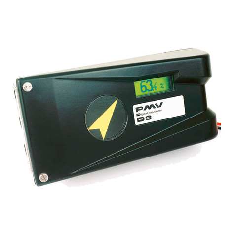
FIAMA P1XT Series User manual

data: 13/03/03 file: P1X_T_ing.doc Rev: 1.1 pag 1 di 11
The P1X_T is a programmable single-axis positioner with microprocessor and relay outputs that processes
signals supplied by incremental transducers such as encoders, magnetic lines, optical lines, etc.
The control of the positioning is made through the voltage analogue output, that may be set-up as 10/+10V or
0/10V or in current output 4/20mA. Other features are the relais outputs of Start/Onward/Backward, end of
positioning and the inputs of: Start, Emergency, Preset, Pieces-counter, all optoisolated.
The axis dimension is displayed on high brightness six-digit display (reading scale -99999, +999999) and three
auxiliary displays show the set dimension, the machine constants, and the processing parameters.
The keyboard with 16 keys and 8 function indicators make the positioner use and setting up easy.
The P1X_T can memorize up to 99 dimensions to create positioning programmes giving the possibility to
manage for every dimension the number of parts that are to be processed in sequence as well as the number
of cycle repetitions. In order to optimize positioning accuracy there are some parameters that can
counterbalance system inertia, clearances, and wear and tear of mechanical couplings.
Find below the other features characterising the instrument: automatic/semiautomatic, manual functioning
mode, absolute/line, single positioning, blade thickness compensation, zero research, inputs and outputs test;
and serial connection RS232 or RS485 with MODBUS RTU protocol to dialogue with remote units.
The keeping of data when there is no power supply is guaranteed by a non volatile EEPROM memory.
The instrument is enclosed in a panel box 72x144 conforming to the DIN 43700 standard.
Front view
Back view
12345678910 11 12 13 14 15 16 17 18 19 20 21 22
Positioner with analogue output
P1XT
P1X0T
P1X1T
P1X2T
P1X3T
+
-
START STOP
MAN ZERO SING
A
/S
PROG COST TEST CYCL
1234
5678
12
54
3
.
789
6
<
<< >>
>
0
C
PE

data: 13/01/16 file: P1X_T_ing.doc pag 2 di 11
Inputs description
The positioner is controlled by 4 optoinsulated inputs that are:
START: active from open to close; it starts the positioning;
EMERGENCY: it must usually be closed; if it is open, it stops the positioning;
WORK COUNTER: work counter input; at the end of every positioning the instrument waits for a switchover
from closed to open of the work counter input in order to carry on the subsequent positioning;
RESET: active from closed to open; it determines the resetting/presetting of the dimension or the zero
research.
For the relevant connections see wiring diagram on page 10
Outputs description
The positioner can manage the following outputs:
STOP/ONWARD/BACKWARD: it controls the speed and the motion direction of the positioned axis,
END OF POSITIONING: contact that closes at the end of positioning,
AUXILIARY OUTPUT(AUX): programmable auxiliary contact (end of cycle, work number, etc),
ANALOGUE OUTPUTS in current 4/20mA and in voltage, set-up between 0/10V and -10/10V.
For the relevant connections see wiring diagram on page 10
Description of the front panel
The display1 always displays the axis dimension, whereas the other displays show different parameters as a
function of the positioner status.
The function indicators show the currently selected function.
PROGRAMMING
The keys used for programming are the following:
PFunction choice programming
EEnter to confirm the entered values
CClear to cancel/enter values
START - Increment or start key(only in the automatic/semiautomatic function)
STOP + Decrement or stop key (only in the automatic/semiautomatic function)
The programming and the use of the positioner is based on 8 main functions the selection of which is obtained
by pressing the P key followed by the relevant numerical key. The default function present when the tool is
switched on is the automatic/semiautomatic function (A/S); when the Pkey is pressed, the DISPLAY2 will
display the 0+writing (function choice) followed by the numerical key corresponding to the wished
+
-
START STOP
MAN ZERO SING
A
/S
PROG COST TEST CYCL
1234
5678
C
12
54
3
.
789
6
<
<< >>
>
DISPLAY 4
DISPLAY 3
DISPLAY 1
DISPLAY 2
INDICATORI
FUNZIONE
EP0

data: 13/01/16 file: P1X_T_ing.doc pag 3 di 11
function according to the following table:
KEY FUNCTION
INDICATOR ASSOCIATED FUNCTION
1MAN Manual axis movement
2ZERO Zero setting/presetting or zero research
3SING Immediate positioning at a given dimension
4A/SAutomatic/semiautomatic positioning
5PROG Writing of dimensions and positioning programmes
6COST Setting of positioner machine parameters
7TEST Inputs/outputs tests
8CYCL Setting of the number of cycles to be carried out
NOTA BENE: in order to ease the association between the wished function and the corresponding number, on
the front panel next to every function indicator it is reported the number corresponding to the associated
function.
1. MANUAL AXIS MOVEMENT (MAN)
The manual function enables to move the axis forward/backward in slow/fast mode by pressing the
numerical keys according to the following table:
KEY AXIS MOVEMENT
7 << backward fast
9 >> forward fast
4 < backward slow
6 > forward slow
NB: in order to move the axis the EMERGENCY input must be closed.
2. ZERO SETTING/PRESETTING OR ZERO RESEARCH (ZERO)
Through this function it is possible to zero set or set at a wished value (preset) the dimension of the axis
or to carry out an automatic zero research (with encoder zero notch or zero micro) to zero set or preset
the dimension.
Manual zero setting or presetting
By pressing the Ekey or by enabling the PRESET input in the terminal box it is possible to zero set or to
carry out a presetting of the dimension as a function of what was set in the constant %on page 7
Automatic zero setting or presetting (zero research)
By enabling the START input in the terminal box (if the constant %is set to the proper value see
page 7) the zero research is started; it occurs with the backward shifting of the axis at slow speed. When
the axis meets the zero notch the dimension is set to zero and the movement is interrupted.
In order to use this function it is necessary that the zero microswitch (or the proximity switch) is connected
to the PRESET input of the positioner.
3. IMMEDIATE POSITIONING AT A SINGLE DIMENSION (SING)
This mode was created to immediately position the axis at a given dimension without intervening on the
positioning programmes. Press the Ckey, enter the dimension through the numerical keypad, confirm by
pressing Eand close the START input to start the movement of the axis or hold down the START- key for
about 2 seconds. If the EMERGENCY input is closed, the positioner controls the motion to reach the set
dimension. Once the axis reached the set position, it is possible to enable the END OF POSITIONING and
AUX outputs according to what is set in the 0/ constant (see page 6)

data: 13/01/16 file: P1X_T_ing.doc pag 4 di 11
4. AUTOMATIC/SEMIAUTOMATIC POSITIONING (A/S)
The automatic/semiautomatic function carries out the selected programme. The programme selection
can be obtained in 2 ways:
- Press the Ckey and insert in display 3 the index of the dimension corresponding to the first step of
the programme to be carried out then confirm with Eor,
- Press the
Ckey and select through the + and – keys the first dimension of the programme and
confirm with E.
Once selected the programme, display 3 will show the index of the dimension while on display 2 the
corresponding dimension will be displayed.
To start the positioning close the START input in the terminal box or hold down the START- key for about 2
seconds. The axis will shift towards the first dimension of the programme and when reached it the axis
will be stopped and the end of positioning output will be enabled for a time equal to that set in the //
constant (see page 6). Before going on with the subsequent dimensions the positioner waits for the
enabling of the WORK COUNTER and START inputs according to what was set in the machine
/constants (see page 55).
By pressing the STOP+ key it is possible to interrupt the positioning; to resume it press START- for 2
seconds or close the START input or open the emergency input to quit the positioning programme.
As to the writing of the dimension programmes see the following paragraph.
5. WRITING OF DIMENSIONS AND POSITIONING PROGRAMMES (PROG)
By programme we mean a series of dimensions to be executed in sequence where, for every dimension,
it is possible to set the number of parts to be processed and the enabling of the auxiliary output AUX.
The positioner can memorize 99 dimensions that may be organised into positioning programmes. The
length of the single programmes is limited only by the total number of memorised dimensions, which must
not exceed 99 (for instance it is possible to create as ultimate limits either 99 programmes made by a
single dimension or one single programme made by 99 dimensions).
The modification of the dimensions is protected by a password; the password is requested through the
display of letter P on display3 and of three zeroes (the first one of them is blinking) on display2. Enter the
number 273 and confirm with E. In case of wrong password entry the instrument leaves the
programming phase. The request of the password in order to have access to the programme dimensions
may be excluded by opportunely setting the - constant (see on page 7).
Dimension setting
Display3 shows the programme index (or programme step) of the current dimension (from 1 to 99), the
display2 shows the value of the wished dimension and the display4 the -/ writing.
To select the dimension which is to be modified there are two modes: with the START- and STOP+ keys it
is possible to scroll all the dimensions in sequence and to select the dimension to be modified or to press
the Ckey for about 2 seconds until the dimension index on display3 starts blinking; then introduce the
value of the dimension index that is to be modified and confirm with the Ekey.
After selecting the dimension to be modified, press the Ckey, enter the wished numerical value and
confirm with E.
Setting of the number of pieces
Then the programme will make the request of the number of parts to be processed in sequence; display4
will display the + writing, press the Ckey, enter the wished number of pieces and confirm with E.
NB: If a number of pieces=0 is set, the positioner does not wait for the enabling of the PIECES COUNTER
input to carry on with the positioning at the subsequent dimension.
Setting of the kind of dimension, of the end of programme and of the enabling of the auxiliary
output
After the number of parts it is necessary to programme the dimension mode constants; display4 will
display the writing while display2 will show the following:

data: 13/01/16 file: P1X_T_ing.doc pag 5 di 11
AUX output enabling
output not enabled (default),
-
--
-the output is enabled when the set dimension is reached,
+
++
+the output is enabled when the set number of parts is reached.
For every programme step it is possible to decide whether enabling the AUX
output when the set dimension is reached, or when the set number of parts
is reached, or not. In case the decision to enable the AUX output is made,
the output remains enabled for all the time set in the /0 constant (see
page 6).
End of programme
the dimension corresponds to one step of the programme (default),
the dimension corresponds to the end of the programme.
This constant enables to attribute to the current dimension the end of the
programme.
Absolute/relative dimension
the set dimension is absolute (default),
.
..
.the set dimension is relative.
The set value for the dimension to be processed can be expressed either in
an absolute way, that is it may be referred to the axis zero point, or in a
relative way, that is it may be referred to the current position of the axis.
In order to change the previous constant values use the START- key to switch from one value to the other
and the STOP+key to switch to the following constant. After setting all the wished values, confirm through
the Ekey.
6. SETTING OF POSITIONER MACHINE PARAMETERS (COST)
Through this function all the machine constants that adjust the positioner functioning may be entered. In
order to modify the constants the password 273 is always needed. Then all the constants are described.
1) Blade thickness
If a value other than zero is set all the set positioning dimensions will be increased by that value. This
constant is used for the applications that need cutting with material removal.
2) PreStop /
//
/
The positioner stops the axis movement when it reaches the dimension amounting to the difference
between the set dimension and the PreStop value. This parameter enables to counterbalance the
positioning inertia in systems with constant inertia. It is advisable to enter the PreStop parameter after
setting all the other machine constants. In order to obtain the correct PreStop value it is necessary to
carry out a positioning and to calculate the difference between the set dimension and the dimension being
actually reached by the axis.
3) Slow dimension -+/
-+/-+/
-+/
The positioner enables the slow output when the axis reaches a dimension amounting to the difference
between the set dimension and the Slow dimension. By setting the zero value, the Slow output is always
disabled (the movement is always in the fast mode).
4) Absolute/Line functioning mode +
++
+
In the Absolute functioning mode (setting A) all the set dimensions are referred to the absolute zero, while
in the Line mode (setting L) the set dimensions are related to the last carried out positioning; that is the
instrument zero sets the current dimension before carrying out any positioning.
5) Automatic/Semiautomatic functioning mode 0/
0/0/
0/
In the Automatic functioning mode (setting A) the beginning of the positioning is determined by the
switchover of the START input from open to closed; the following positioning operations are automatically
carried out for all the time during which the START input remains closed. The automatic process is
stopped when the START input is opened.
In the Semiautomatic functioning (setting S) the positioning starts with the switchover of the START input
from open to closed: after reaching the target dimension the process is stopped and only restarts if the
START input switches from open to closed.

data: 13/01/16 file: P1X_T_ing.doc pag 6 di 11
6) Duration of the End of Positioning output enabling (Cutting time) //
////
//
At the end of positioning, the END OF POSITIONING output is enabled for a time that can be set from 100 to
9999 milliseconds; by setting 0 the End of Positioning output remains enabled until the next start
command is given.
7) Duration of the Auxiliary output enabling /0
/0/0
/0
It determines the enabling time of the AUX output that can be set from 100 to 9999 milliseconds (see
“Aux output enabling” on page 5 ).
8) Setting of outputs for immediate positioning 0/
0/0/
0/
With this constant it is possible to set the enabling of the END OF POSITIONING and AUX outputs in the
“Immediate positioning at a single dimension” function (see page 3). Through the following table it is
possible to select the various options:
0/ END OF POSITIONING
OUTPUT
AUX
OUTPUT
0 Disabled Disabled
1Enabled for the // time. Disabled
2 Disabled Enabled for the /0 time
3 Enabled by pressing the key 5 Disabled
4 Disabled Enabled by pressing the key 8
9) Clearances recovery dimension -.
-.-.
-.
By setting a value other than zero the enabling to the clearances recovery in the onward positioning is
obtained: that is the same axis exceeds the positioning dimension of one value amounting to the set
Clearances Recovery Dimension and then waits for a time equal to the Motion Reversing Time to go back
to the target dimension.
10) Motion Reversing time /+
/+ /+
/+
In order to avoid excessive strain on the handling system, it is possible to set a waiting time, ranging
between 0 and 9999 milliseconds, for all the motion reversing manoeuvres.
11) Deviation dimension -/
-/-/
-/
By setting this constant to a value differing from zero, at the end of the positioning the instrument waits for
the switchover from open to closed of the WORK COUNTER input to carry out an onward shifting of a
dimension equal to the Deviation Dimension; after that, when a time equal to the Deviation Return Waiting
Time has elapsed, the instrument returns to the set dimension.
If a Deviation Dimension equal to zero is set this function is disabled.
12) Deviation Dimension Waiting Time ///
//////
///
Time interval after which the return from the deviation dimension is obtained (active only if a Deviation
Dimension other from zero is set); it can be set between 0 and 9999 milliseconds.
13) Displayed value for an encoder turn
The instrument can correct counted pulses by multiplying them by a coefficient amounting to the ratio
between the and constants; if the two constants are opportunely set it is possible to
display the wished value for a given number of pulses counted on inputs. The value to be set in this
parameter represents the value to be displayed connected to an encoder turn, that is the multiplier factor
of input pulses.
The range of admissible values is 0 ÷999999.
14) Number of pulses for encoder turn
The value to be set in this parameter represents the number of pulses for a turn of the encoder that is the
divisor factor of input pulses.
The range of admitted values is 0 ÷999999.
Example:
Let us consider a 100 pulses/turn encoder and for every turn an axis shifting of 123,4567. In order to
display the value of 123,45: set =12345 and =100; in order to position the decimal point in
the 2nd position set N.DEC=2.

data: 13/01/16 file: P1X_T_ing.doc pag 7 di 11
NOTE: to reduce the error made by truncating the digits after the radix point in the value to be displayed, it
is advisable to multiply and by 10 or 100 or 1000 in order to consider the maximum
number of significant digits; with the above mentioned values by multiplying everything by 100 it is
possible to obtain =123456 and =10000 by thus obtaining 6 significant digits (instead of 4)
for .
15) Number of decimals +%
+%+%
+%
It sets the number of decimals of the display that can be set between 0 to 5.
16) Preset dimension ./
././
./
Value of the dimension that will be displayed by using the zero setting function or by enabling the PRESET
input in the terminal box according to what was set in the following constant.
17) Zero setting mode ,%
,%,%
,%
The setting of the zero setting mode enables to select the effect of the Ekey or of the PRESET input
according to the following table:
,% KEY E RESET INPUT
0 DISABLED RESET
1 DISABLED PRESET
2 RESET RESET
3 PRESET RESET
4 RESET PRESET
5 PRESET PRESET
6 RESET DISABLED
7 PRESET DISABLED
8 DISABLED DISABLED
9 DISABLED PRESET in zero automatic
research mode 1
10 DISABLED PRESET in zero automatic
research mode 2
Modes 9 and 10 refer to the zero research automatic cycle (see on page 3) the zero setting/presetting or
zero research function).
Zero automatic research mode1
In the automatic zero setting function when the START- key is pressed the slow backward motion of the
axis is started searching for the zero input. When the zero point is reached the axis motion continues for
2 seconds more and then stops and carries out the dimension presetting.
Zero automatic research mode 2
In the automatic zero setting function when pressing the START- key the slow backward motion of the axis
is started searching for the zero input. When the zero point is reached the axis is stopped and the
dimension presetting is carried out.
18) Dimensions protected by password -
--
-
In order to prevent the accidental or unintentional alteration of the positioning dimensions, the instrument
gives the opportunity to protect with a password the access to the dimensions. It is thus possible to select
between 0 , dimensions protected by password, and 1 ,dimensions unprotected by password.
19) Time constant for acceleration ramp /.
/./.
/.
Starting the positioning axis, before reaching the maximum speed, the positioner produces an
acceleration ramp with a time constant that may be set-up between 50 to 9999 milliseconds.
20) Time constant for deceleration ramp /.%
/.%/.%
/.%
During the positiong, reached the Slow value, by the passing from the speed Fast to the speed Slow, it
produces a decelaration ramp with a time constant that may be set-up between 50 and 9999 milliseconds.

data: 13/01/16 file: P1X_T_ing.doc pag 8 di 11
21)Value of the analogue output for the speed Fast
The output value which corresponds to the speed Fast is stated in per cent of the maximum value and
that can be set-up from 1 to 100.
22) Value of the analogue output for the speed Slow
The output value which corresponds to the speed Slow is stated in per cent of the maximum value and
that can be set-up from 1 to 100.
23) Working way for output -10/+10V o 0/10V + ./
+ ./+ ./
+ ./
Through this constant is possible to select the type of output: setting 0 (driving gear) the output goes from
-10V to +10V, positive voltage for the onward gear and negativ for the backward gear, setting 1 (inverter)
the output goes from 0 to +10V and the gear wise is discriminated by the relay of Forward/Backward.
By using the current output 4/20 mA set this constant to 1.
24) Dimensions lower limit +
++
+
Due to safety reasons the positioner prevents the entry of dimensions lower than the value set in this
constant and interrupts the axis motion if during the positioning the dimension becomes lower than this
limit. Don't set values that are upper then the Upper Limit for the values (next constant) or the positioner
will not accept the start drives
25) Dimensions upper limit 0
00
0
As for the previous constant, the positioner prevents the entry of dimensions exceeding the value set in
this constant and interrupts the axis motion if during the positioning the dimension exceeds this limit. Don't
set the values that are lower then the Lower Limit for the values (previous constant) or the positioner will
not accept the start drives.
26) Display mode %
% %
%
Setting this function gives the possibility to convert the quota visualized on the display in a quota
expressed in inch fraction or degrees. Keeping pressed the key Pfor abt. 3 seconds is possible proceed
to a type of visualization to an other.
The constant % defines the type of conversion of the quota: using keys START- and START+
select the visualization needed according to the following table
% DISPLAY FUNCTION
%# disabled
% From tenth of mm to thousandths of an inch
% From tenth of mm to hundredths of an inch
From mm to hundredths of an inch
% From mm to tenths of an inch
From cm to hundredths of an inch
% From dm to inches
.% Sexagesimal degrees with display in degrees and prime numbers
.. Sexagesimal degrees with display in degrees

data: 13/01/16 file: P1X_T_ing.doc pag 9 di 11
7. INPUTS/OUTPUTS TEST (TEST)
In order to have access to the test function it is necessary to enter the password 273.
In the inputs test function display3 will display the / (Test Input) message and display2 will display 4
hyphens. Every hyphen indicates one input: the input in the low position (high) indicates that the input is open
(closed).
The inputs test consists in closing the input switches and check that the display corresponds to the figure
below:
START
EMERGENCY
PRESET
PIECESCOUNTER
DISPLAY2 INPUT CLOSED
NONE
Then go to the outputs test by pressing the Ekey; the display3 will display / (Test Output).
In order to enable/disable the outputs press the numerical keys indicated in the following figure: the position of
the hyphen indicates the output status; to the hyphen in the high position (low) corresponds an enabled output
(not enabled).
START
END POSITIONING
FORWARD/BACKWARD
SLOW/FAST
DISPLAY2 START OUTPUT
NONE
AUX OUTPUT
KEY TO BE PUSHED
NONE
1
2
3
4
5
By pressing the Ekey it is possible to go back to the inputs test; in order to leave the test function, press P.
8. SETTING OF THE NUMBER OF CYCLES TO BE CARRIED OUT (CYCL)
By number of cycles we mean the number of repetitions of the positioning programme. The automatic
functioning mode involves the possibility to repeat the selected programme. By setting a number of cycles
greater than 1, once the last dimension of the positioning programme has been carried out, at the next
command by the work counter input the positioner restarts from the first dimension of the selected programme.

data: 13/01/16 file: P1X_T_ing.doc pag 10 di 11
WIRING DIAGRAM
M1
BACKWARD
FORWARD
PIECES COUNTER input
17
18
1
2
3
4
5
6
7
8
9
10
11
12
13
14
15
16
19
20
21
22
START
END POSITIONING relay
EMERGENCY input
PRESET input
Transducer input
(see “ Transducer wiring diagram ”)
AUX OUTPUT relay
START/FORWARD/BACKWARD relais
GND
A
/A
B
/B
+12V
24 Vac+24VDC 230 Vac 115 Vac
P1X2TP1X3T P1X1T P1X0T
0000
START input
analog output GND
analog output V+
analog output I+
Transducer wiring diagram
18
20
17
19
21
22
GND
A
B
+12V
/A
/B
GND
A
B
+Vcc
Connection bidirectional encoder open-
collector NPN or push-pull output
NPN
A
B
+12V
/A
/B
GND
GND
A
B
+Vcc
PNP
19
22
20
18
17
21
Connection bidirectional encoder open-
collector PNP or push-pull output

data: 13/01/16 file: P1X_T_ing.doc pag 11 di 11
TECHNICAL FEATURES
•Power supply P2X0 115Vac, ±10%
P2X1 230 Vac, ±10%
P2X2 24 Vac, ±10%
P2X3 24 Vdc ±20%
•Power 7VA
•Line frequency 50/60 Hz
•7 segments display 6 digit for dimension visualisation
2 digit for guided programming
•DIN 43700 case black, self-extinguishing, shock resistant
•Dimensions 72x144x160 mm
•Perforation profile 70x142 mm
•Frontal protection degree IP54
•Transducer power supply 12 Vdc (100mA max.)
•Counting input NPN e PNP open collector
Push Pull
Line driver differential 12V
•Maximum counting frequency 100 KHz
•Operating procedure (mode) Semiautomatic/Automatic
Absolute/line
Manual
Single positioning
Test
•Possibility to create working programmes 99 steps of program memory with the possibility of
specifying the number of pieces and the number of
cycle repeats
Data storage with the machine switched off by EEPROM memory
•Extractable terminal (junction box)
•Input/output test
•Relays output 250Vac 250Vac/10A (resistive
load)
Start/forward/backward
Positioning end
Aux outputs
•Inputs ON-OFF optoisolated 12Vdc preset
emergency
piececounter
start
•Analogue output voltage: selectable between -10/+10, 0/10V
current: 4/20 mA
•Resolution 11 bits + sign
•Thermal stability 200 ppm/°C max
•Minimum load voltage output 1 Kohm
•Maximum load output current 500 Ohm
•Accuracy analogic output ±1% FS max
•Directive: Electromagnetic compatibility 2014/30/EU, Low voltage 2014/35/EU, RoHS 2011/65/EU
This manual suits for next models
4
Table of contents
Other FIAMA Valve Positioner manuals


