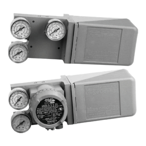
GE FVP110 User manual

GE Energy
Masoneilan* Products
FVP*110 (Rev B)
Maintenance Manual
FVP110 offers advanced control
technology for pneumatically
actuated valves.

Warranty
Items sold by GE Energy are warranted to be free from defects in materials and
workmanship for a period one (1) year from first use or eighteen (18) months from
delivery provided said items are used according to GE recommended usages. GE
reserves the right to discontinue manufacture of any product or change product
materials, design or specifications without notice.
Software is warranted for ninety (90) days from delivery.
This instruction manual applies to the following instruments and approved software:
FVP110*II Valve Positioner and ValVue*FF software.
The FVP110 positioners are warranted for use only with interface software approved by
GE Energy. Consult GE Masoneilan factory locations for approved software listing.
About this Guide
This instruction manual applies to the following instruments and approved software:
❑ValVue FF software
❑FVP110
The information contained in this manual, in whole or part, shall not be transcribed or
copied without GE Masoneilan’s written permission.
In no case does this manual guarantee the merchantability of the positioner or the
software or its adaptability to a specific client needs.
Please report any errors or questions about the information in this manual to your local
supplier or visit www.masoneilan.com.
The information contained in this manual is subject to change without prior notice.
Should any doubt or error be found in this manual, submit inquiries to your local dealer.
Changes to specifications, structure, and components used may not lead to the revision
of this manual unless such changes affect the function and performance of the
instrument.
Copyright
The complete design and manufacture is the intellectual property of GE Energy.
Masoneilan*, FVP*, and SVI*are registered trademarks of GE Energy. All other
trademarks are property of their respective corporations. All other trademarks are the
property of their respective corporations. All software is the intellectual property of GE.
Copyright 2012 by GE Energy. All rights reserved.
P/N 720009602-888-0000 Rev. B

iii
Contents
Introduction .....................................................................................................................................1
Conventions Used in This Manual .............................................................................................2
For Safe Use of Product ............................................................................................................3
Installation ............................................................................................................................3
Wiring ...................................................................................................................................3
Operation .............................................................................................................................3
Maintenance.........................................................................................................................4
ATEX Documentation ................................................................................................................4
Safety .............................................................................................................................................7
FVP110 Product Safety .............................................................................................................7
Nameplate..................................................................................................................................8
Transport....................................................................................................................................8
Storage ......................................................................................................................................9
Choosing the Installation Location .............................................................................................9
Use of a Transceiver..................................................................................................................9
Insulation Resistance Test and Withstand Voltage Test..........................................................10
Insulation Resistance Test Procedure ...............................................................................10
Withstand Voltage Test Procedure ....................................................................................10
Notes for Safety .......................................................................................................................11
EMC Conformity Standards .....................................................................................................11
Installation of Explosion Protected Type Positioner.................................................................11
FM Certification ..................................................................................................................11
A) FM Intrinsically Safe Type ...................................................................................11
B) FM Explosionproof Type ......................................................................................17
C) FM Nonincendive approval ..................................................................................18
NFM010-A12 ...........................................................................................................18
CENELEC ATEX (KEMA) Certification ..............................................................................19
Technical Data .........................................................................................................19
Supply Unit ...............................................................................................................22
Cable ........................................................................................................................23
Terminators ..............................................................................................................23
Field Instruments ......................................................................................................23
Number of Devices ...................................................................................................24
Entity Model .......................................................................................................................24
Field Instruments ......................................................................................................25
Number of Devices ...................................................................................................25
B) CENELEC ATEX (KEMA) Flameproof Type ........................................................25
C) CENELEC ATEX Type of Protection n ................................................................26
CSA Certification ......................................................................................................30
TIIS Certification .......................................................................................................31

FVP 110 Fieldbus Valve Positioner Manual
iv
GE Energy
Low Voltage Directive ..............................................................................................................31
Pollution Degree 2 .............................................................................................................31
Installation Category I ........................................................................................................31
Part Names ..................................................................................................................................33
Appearance and Part Names...................................................................................................33
Single Acting Type .............................................................................................................33
Double Acting Type............................................................................................................33
Block Diagram..........................................................................................................................34
Installing the FVP110 on the Actuator .........................................................................................35
General ....................................................................................................................................35
General Installation Procedures: FVP110 to the Actuator .......................................................35
Installing FVP110 on a Linear-motion Control Valve .........................................................36
Installing FVP110 on Rotary-motion Control Valve............................................................40
A/M Switching ..........................................................................................................42
Camflex Rotary Valve Mounting ........................................................................................43
87/88 Reciprocating Valve Mounting .................................................................................46
Mounting the FVP110 with NAMUR Kits............................................................................49
Wiring and Piping .........................................................................................................................51
General ....................................................................................................................................51
Piping .......................................................................................................................................52
Air Supply...........................................................................................................................52
Pneumatic Piping ...............................................................................................................52
Wiring.......................................................................................................................................54
Recommended Cables ......................................................................................................54
General-use Type and Intrinsically Safe Type ...................................................................54
Flameproof Type (JIS) .......................................................................................................55
Grounding ................................................................................................................................57
Setup ...........................................................................................................................................59
General ....................................................................................................................................59
Set Basic Parameters ..............................................................................................................60
Carrying out Tuning .................................................................................................................61
Travel Calibration...............................................................................................................63
Check Valve Actions................................................................................................................63
Set Transducer Block Parameters...........................................................................................64
Maintenance ................................................................................................................................67
General ....................................................................................................................................67
Periodic Inspections.................................................................................................................68
Cleaning the Fixed Nozzle .................................................................................................68
Part Replacement ....................................................................................................................69
Replacing the Control Relay Assembly..............................................................................69
Replacing the Screen Filters..............................................................................................70
Replacing the Internal Air Filter..........................................................................................70
Tuning the Pressure Balance of Control Relay..................................................................71

v
Standard Specifications ...............................................................................................................73
Standard Specifications ...........................................................................................................73
Performance Specifications .....................................................................................................77
Model and Suffix Codes...........................................................................................................78
Optional Specifications ............................................................................................................78
Optional Specifications For Explosion Protected Types ..........................................................79
Dimensions ..............................................................................................................................81
About Fieldbus .............................................................................................................................85
Outline......................................................................................................................................85
Internal Structure of FVP110 ...................................................................................................85
Logical Structure of Each Block ...............................................................................................86
System Configuration...............................................................................................................87
Connection of Devices .......................................................................................................88
Integration of DD......................................................................................................................88
Configuration ................................................................................................................................89
Network Design........................................................................................................................90
Network Definition....................................................................................................................90
Definition of Combining Function Blocks .................................................................................92
Setting of Tags and Addresses................................................................................................94
Communication Setting............................................................................................................95
VCR Setting .......................................................................................................................95
Function Block Execution Control ......................................................................................95
Block Setting ............................................................................................................................96
Link Object .........................................................................................................................96
Trend Object ......................................................................................................................97
View Object ........................................................................................................................97
Function Block Parameters..............................................................................................107
Actions of the FVP110 During Operation ...................................................................................109
Block Modes ..........................................................................................................................109
Alarm Generation...................................................................................................................112
Simulation Function ...............................................................................................................113
Resource Block ..........................................................................................................................115
General ..................................................................................................................................115
Alarm Processing...................................................................................................................115
Device Status.........................................................................................................................116
Transducer Block .......................................................................................................................123
General ..................................................................................................................................123
Position-to-flow Rate Characteristic Conversion..............................................................124
FINAL_VALUE and Range...............................................................................................124
Tight-shut and Full-open Actions .....................................................................................125
Backward Path.......................................................................................................................125
FINAL_POSITION_VALUE ..............................................................................................125
Limit Switches ..................................................................................................................126
Auto Tuning............................................................................................................................126

FVP 110 Fieldbus Valve Positioner Manual
vi
GE Energy
Travel Calibration...................................................................................................................129
Online Diagnostics .................................................................................................................129
XD_ERROR .....................................................................................................................129
Fail-safe Action ................................................................................................................131
Operation Result Integration ............................................................................................131
Recording of Revisions ....................................................................................................131
Control Parameters................................................................................................................132
Temperature and Pressure Measurement.............................................................................132
AO Function Block .....................................................................................................................133
General ..................................................................................................................................133
Modes ....................................................................................................................................134
Forward Path .........................................................................................................................134
Fault State........................................................................................................................135
Backward Path.......................................................................................................................135
IO_OPTS and STATUS_OPTS .............................................................................................136
Mode Shedding on Computer Failure....................................................................................137
Initialization at Start................................................................................................................138
Alarm Processing...................................................................................................................139
DI Function Block .......................................................................................................................141
General ..................................................................................................................................141
Modes ....................................................................................................................................142
PV Value (PV_D) ...................................................................................................................142
Filtering ..................................................................................................................................142
Output ....................................................................................................................................142
IO_OPTS and STATUS_OPTS .............................................................................................143
Alarm Processing...................................................................................................................144
Block Alarms ....................................................................................................................144
Discrete Alarm .................................................................................................................144
OS Function Block .....................................................................................................................145
General ..................................................................................................................................145
Modes ....................................................................................................................................146
Output Processing .................................................................................................................146
Backward Path (BKCAL_OUT) ..............................................................................................147
STATUS_OPTS .....................................................................................................................148
Alarm Processing...................................................................................................................148
IS (SIGSEL) Function Block ......................................................................................................149
General ..................................................................................................................................149
Function Supported................................................................................................................150
Supported Modes.............................................................................................................151
Alarm Types.....................................................................................................................151
Mode Handling.................................................................................................................151
Status Handling................................................................................................................151
Initialization ......................................................................................................................151
Power Failure Recovery...................................................................................................151

vii
AR (Arithmetic) Function Block ..................................................................................................153
General ..................................................................................................................................153
Functions Supported ........................................................................................................155
Supported Modes.............................................................................................................156
Alarm Types .....................................................................................................................156
Mode Handling .................................................................................................................156
Status Handling................................................................................................................156
Initialization ......................................................................................................................156
Power Failure Recovery...................................................................................................156
PID Function Block ....................................................................................................................157
General ..................................................................................................................................157
Modes ....................................................................................................................................158
Input Processing ....................................................................................................................159
Setpoint (SP) Limiters ............................................................................................................159
PID Computation....................................................................................................................159
Control Output........................................................................................................................160
Direction of Control Action .....................................................................................................161
Control Action Bypass............................................................................................................161
Feed-forward..........................................................................................................................162
External-output Tracking (LO)................................................................................................162
Measured-value Tracking ......................................................................................................163
CONTROL_OPTS..................................................................................................................163
Initialization and Manual Fallback (IMan)...............................................................................164
Manual Fallback.....................................................................................................................164
STATUS_OPTS ...............................................................................................................165
Auto Fallback .........................................................................................................................165
Mode Shedding on Computer Failure ....................................................................................166
Alarms....................................................................................................................................167
Block Alarm (BLOCK_ALM) .............................................................................................167
Process Alarms ................................................................................................................168
Diagnostics ................................................................................................................................169
General ..................................................................................................................................169
Integration Functions .............................................................................................................170
Signature Measurement Functions ........................................................................................171
Signature Measurement Procedure .................................................................................171
Signatures and Relevant Parameters ..............................................................................172
Troubleshooting .........................................................................................................................175
What to Do First .....................................................................................................................175
Troubleshooting Communications .........................................................................................176
Troubleshooting Function Block Parameters .........................................................................176
Troubleshooting Valve Control...............................................................................................178
Troubleshooting AutoTuning..................................................................................................181
Troubleshooting Position, Pressure, and Temperature Sensors ...........................................182

FVP 110 Fieldbus Valve Positioner Manual
viii
GE Energy
Function Block Parameters ........................................................................................................183
Parameters of Resource Block ..............................................................................................184
Parameters of Transducer Block ...........................................................................................188
Parameters of AO Block ........................................................................................................198
Parameters of DI Block ..........................................................................................................201
Parameters of OS Block ........................................................................................................203
Parameters of PID and PID2 Blocks (Optional) .....................................................................205
Parameters of IS (SIGSEL) Block..........................................................................................209
Parameters of AR (Arithmetic) Block .....................................................................................212
IO_OPTS - Availability of Options for Each Block..................................................................215
STATUS_OPTS - Availability of Options for Each Block .......................................................215
CONTROL_OPTS - Availability of Options for Each Block....................................................216
Link Master Functions ................................................................................................................217
Link Active Scheduler ............................................................................................................217
Link Master ............................................................................................................................218
Transfer of LAS......................................................................................................................218
LM Functions .........................................................................................................................220
LM Parameters ......................................................................................................................221
LM Parameter List............................................................................................................221
Descriptions for LM Parameters ......................................................................................224
FAQs......................................................................................................................................229
DD Methods and DD Menu ........................................................................................................231
Overview................................................................................................................................231
DD Methods ...........................................................................................................................231
Transducer Block .............................................................................................................232
Setup Wizard ..........................................................................................................232
Auto Tuning Wizard ................................................................................................232
Search Stop Points ................................................................................................233
Control Parameter Tuning ......................................................................................233
Travel Calibration ...................................................................................................233
Operational Parameter Configuration ....................................................................234
Release Fail Safe ...................................................................................................234
Instant Trouble Shooting ........................................................................................235
Self Check Execution .............................................................................................235
Signature Execution ...............................................................................................235
Upload Signature Data ...........................................................................................236
Upload Signature Header Data ..............................................................................236
AO Block ..........................................................................................................................237
Simulation Enable ..................................................................................................237
Simulation Disable .................................................................................................237
OS Block ..........................................................................................................................238
X-Y Scaling ............................................................................................................238
Software Download ....................................................................................................................239
Benefits of Software Download..............................................................................................239
Specifications.........................................................................................................................240

ix
Preparations for Software Downloading ................................................................................240
Software Download Sequence...............................................................................................241
Download Files ......................................................................................................................242
Steps after Activating a Field Device .....................................................................................243
Troubleshooting .....................................................................................................................244
Resource Block’s Parameters Relating to Software Download .............................................245
Software Download System/Network Management VFD Parameters ...................................247
Comments on System/Network Management VFD Parameters Relating to Software Download
248
Position Adjustment of Feedback Lever ....................................................................................251
Manual Tuning Guideline ...........................................................................................................253
General ..................................................................................................................................253
Control Parameter Tuning Procedure ....................................................................................254
Fast Response .................................................................................................................254
Modifying overshoot ...............................................................................................254
Improving the Stabilization Time ............................................................................255
Improving the Response Time ...............................................................................255
Checking Hunting Operation ..................................................................................255
Moderate Response.........................................................................................................255
Improving the stabilization time ..............................................................................255
Modifying overshoot ...............................................................................................256
Improving the Response Time ...............................................................................256
Checking Hunting Operation ..................................................................................256
Moderate Response with a Flat Overshoot......................................................................256
Occurrence of a Limit Cycle ...................................................................................256
Modifying Overshoot ..............................................................................................257
Improving the Stabilization Time and Slow Overshoot ...........................................257
Improving the Response Time ...............................................................................257
Checking Hunting Operation ..................................................................................257
Examples of Tuning Control Parameters ...............................................................................258
Description of Control Parameters.........................................................................................259
SERVO_GAIN..................................................................................................................259
SERVO_RESET...............................................................................................................259
SERVO_RATE .................................................................................................................260
SERVO_RATE_GAIN ......................................................................................................260
SERVO_DEADBAND.......................................................................................................260
SERVO_OFFSET ............................................................................................................261
BOOST_ON_THRESHOLD [1], [2] ..................................................................................261
BOOST_OFF_THRESHOLD [1], [2] ................................................................................261
BOOST_VALUE [1], [2]....................................................................................................261
SERVO_P_ALPHA ..........................................................................................................263
INTERNAL_GAIN.............................................................................................................264

FVP 110 Fieldbus Valve Positioner Manual
x
GE Energy
Installation and Operating Precautions for JIS Flameproof Equipment .....................................265
General ..................................................................................................................................265
Electrical Apparatus of Flameproof Type of Explosion- Protected Construction ...................266
Terminology ...........................................................................................................................266
Installation of Flameproof Apparatus .....................................................................................267
External Wiring for Flameproof Apparatus.............................................................................267
Maintenance of Flameproof Apparatus..................................................................................269
Selection of Cable Entry Devices for Flameproof Type .........................................................271
Customer Maintenance Parts List ..............................................................................................273

xi
Figures
1 Nameplate...........................................................................................................................8
2 Installation Diagram (Intrinsically safe, Division 1 Installation) .........................................13
3 Passive Devices................................................................................................................15
4 Installation Diagram (Nonincendive, Division 2 Installation) .............................................16
5 Installation Drawing...........................................................................................................18
6 FISCO Model ....................................................................................................................22
7 Entity Model ......................................................................................................................24
8 Installation Diagram ..........................................................................................................27
9 Type of Electrical Connection ...........................................................................................28
10 Nameplates.......................................................................................................................29
11 Production Year ................................................................................................................30
12 Single Acting Parts............................................................................................................33
13 Double Acting Parts ..........................................................................................................33
14 Block Diagram...................................................................................................................34
15 FVP Installed on Linear-motion Valve/Actuator ................................................................36
16 Feedback Levers ..............................................................................................................36
17 Stroke of Lever..................................................................................................................37
18 Disassembling a Lever Assembly.....................................................................................38
19 Stopper .............................................................................................................................38
20 Attaching Lever and Clamp...............................................................................................39
21 Checking Position at Which Clamp Should Be Fixed .......................................................39
22 FVP Installed on Rotary-motion Valve/Actuator................................................................40
23 Allowable Range of Rotation Angle of Feedback Shaft ....................................................41
24 Stopper .............................................................................................................................41
25 Inserting Pin into Hole of Feedback Lever (In case of using F9176HA) ...........................42
26 A/M Selector Switch..........................................................................................................43
27 Camflex Mounting .............................................................................................................44
28 FVP110 Mounted on a Camflex Valve (Side View) ..........................................................45
29 Lever for 87/88 Multi-Spring Actuator ...............................................................................46
30 FVP Mounted on Reciprocating Valve ..............................................................................47
31 Namur Mounting Kit ..........................................................................................................49
32 Pneumatic Piping Port ......................................................................................................53
33 Wiring................................................................................................................................54
34 Typical Wiring Using Flexible Metal Conduit.....................................................................55
35 Typical Cable Wiring Using Flameproof Packing Adapter ................................................55
36 Installing Flameproof Packing Adapter .............................................................................56
37 Typical Wiring Using Flameproof Metal Conduit...............................................................57
38 Position-to-flow Rate Characteristic Type.........................................................................64
39 Shrouding Bolts.................................................................................................................67
40 Cleaning the Nozzle..........................................................................................................68
41 Replacing the Control Relay Assembly.............................................................................69
42 Replacing the Screen Filters.............................................................................................70
43 Replacing the Internal Air Filter.........................................................................................70

FVP 110 Fieldbus Valve Positioner Manual
xii
GE Energy
44 Tuning the Pressure Balance of Control Relay.................................................................71
45 Model and Suffix Codes....................................................................................................78
46 Single Acting Actuator Dimensions...................................................................................81
47 Double Acting Actuator Dimensions .................................................................................82
48 Terminal Configuration .....................................................................................................83
49 Logical Structure of Each Block........................................................................................86
50 Cabling..............................................................................................................................88
51 Available Range of Node Addresses ................................................................................91
52 Example of Loop Connecting Function Block of FVP110 with Other Instruments............93
53 Function Block Schedule and Communication Schedule .................................................93
54 Status Transition by Setting PD Tag and Node Address..................................................94
55 SIM.ENABLE Switch.......................................................................................................113
56 Function Diagram of Transducer Block ..........................................................................124
57 Inputs/Outputs of AO Function Block..............................................................................133
58 Function Diagram of AO Function Block.........................................................................134
59 Mode Priority Levels .......................................................................................................138
60 Inputs/Outputs of DI Function Block ...............................................................................141
61 Function Diagram of DI Function Block ..........................................................................141
62 Inputs/Outputs of OS Function Block..............................................................................145
63 Function Diagram of OS Function Block.........................................................................145
64 Examples of Valve Operation Characteristics ................................................................146
65 LOCKVAL and HYSTVAL...............................................................................................147
66 Inputs/Outputs of IS (SIGSEL) Function Block ...............................................................149
67 Function Diagram of SIGSEL Function Block.................................................................150
68 Inputs/Outputs of AR Function Block..............................................................................153
69 Function Diagram of AR Function Block .........................................................................154
70 Inputs/Outputs of PID Function Block.............................................................................157
71 Function Diagram of PID Function Block........................................................................158
72 Control Action Bypass ....................................................................................................161
73 Feed-forward ..................................................................................................................162
74 External-value Tracking ..................................................................................................162
75 Priority Levels .................................................................................................................167
76 Example of Fieldbus Configuration-3 LMs on Same Segment .......................................218
77 Backup of LAS ................................................................................................................218
78 Node Address Ranges....................................................................................................219
79 DlmeBasicInfo (YVP Index 361 (SM)) Example .............................................................219
80 ConfiguredLinkSettingsRecord (YVP Index 369 (SM)) Example....................................220
81 ConfiguredLinkSettingsRecord (YVP Index 369 (SM)) Example....................................220
82 Concept of Software Downloading .................................................................................239
83 Flow of Software Download Procedure ..........................................................................241
84 Checking Position at Which Clamp Should Be Fixed .....................................................252
85 Manual Tuning Flowchart ...............................................................................................253
86 Fast Response................................................................................................................254
87 Moderate Response .......................................................................................................255
88 Moderate Response with a Flat overshoot .....................................................................256
89 Servo Deadband.............................................................................................................260

xiii
90 Boost Threshold 1...........................................................................................................261
91 Boost Threshold 1...........................................................................................................262
92 SERVO_I_SLEEP_LMT and SERVO_DEADBAND .......................................................263
93 SERVO_P_ALPHA Operation ........................................................................................263

FVP 110 Fieldbus Valve Positioner Manual
This page intentionally left blank.

xv
Tables
1 Specifications of Levers ................................................................................................... 37
2 Lever Hole Locations for 87/88 Multi-Spring Actuator ..................................................... 47
3 Turnbuckle Length ........................................................................................................... 48
4 Flameproof Packings and Applicable Cable Outer Diameters......................................... 56
5 Diaphragm, Single Acting Cylinder .................................................................................. 74
6 Diaphragm, Double Acting Cylinder................................................................................. 75
7 Diaphragm, Single Acting Cylinder .................................................................................. 76
8 Diaphragm, Double Acting Cylinder................................................................................. 76
9 Pressure Gauge Connection............................................................................................ 77
10 Optional Specifications .................................................................................................... 78
11 Optional Specifications For Explosion Protected Types .................................................. 79
12 Parameters for Setting Address Range ........................................................................... 90
13 Operation Parameter Values of the FVP110 to be Set to LM Devices ............................ 91
14 Execution Schedule of the FVP110 Function Blocks....................................................... 92
15 Execution Schedule of the FVP110 Function Blocks....................................................... 96
16 Execution Schedule of the FVP110 Function Blocks....................................................... 97
17 View Object for Transducer Block.................................................................................... 98
18 View Object for AO Function Block................................................................................ 101
19 View Object for DI1, DI2 Function Block........................................................................ 102
20 View Object for OS Function Block................................................................................ 103
21 View Object for PID Function Block ............................................................................... 104
22 View Object for Resource Block .................................................................................... 105
23 Indexes of View for Each Block ..................................................................................... 106
24 View Object for IS (SIGSEL) Block ................................................................................ 106
25 AR Block Arithmetic Block Access................................................................................. 106
26 Block Modes .................................................................................................................. 109
27 Examples of Block Mode Combinations and Operation Statuses.................................. 111
28 Alert Objects .................................................................................................................. 112
29 BLOCK_ERROR in Resource Block.............................................................................. 115
30 DEVICE_STATUS_1 ..................................................................................................... 116
31 DEVICE_STATUS_2 ..................................................................................................... 118
32 DEVICE_STATUS_3 ..................................................................................................... 120
33 Correspondence between Channels and I/O Signals .................................................... 123
34 Types of Auto Tuning..................................................................................................... 126
35 AUTO_TUNE_RESULT & TRAVEL_CALIB_RESULT .................................................. 127
36 XD_ERROR ................................................................................................................... 130
37 IO_OPTS of AO Block ................................................................................................... 136
38 STATUS_OPTS of AO Block ......................................................................................... 136
39 SHED_OPT of AO Block................................................................................................ 137
40 BLOCK_ERROR in AO Block ........................................................................................ 139
41 FIELD_VAL_D ............................................................................................................... 142
42 IO_OPTS of DI Block ..................................................................................................... 143
43 IO_OPTS of DI Block ..................................................................................................... 143
44 BLOCK_ERROR in DI Block.......................................................................................... 144

FVP 110 Fieldbus Valve Positioner Manual
xvi
GE Energy
45 STATUS_OPTS of PID Block ........................................................................................ 148
46 STATUS_OPTS of PID Block ........................................................................................ 148
47 PID Control Parameters................................................................................................. 160
48 PID Control Parameters................................................................................................. 161
49 CONTROL_OPTS of PID Block..................................................................................... 163
50 STATUS_OPTS of PID Block ........................................................................................ 165
51 STATUS_OPTS of PID Block ........................................................................................ 166
52 Block Alarm (BLOCK_ALM)........................................................................................... 167
53 Process Alarms.............................................................................................................. 168
54 FVP110’s Parameters Containing Integrated Operation Result Quantity...................... 170
55 Troubleshooting Communications ................................................................................. 176
56 Troubleshooting Function Block Parameters ................................................................. 176
57 Troubleshooting Valve Control ...................................................................................... 178
58 Troubleshooting AutoTuning.......................................................................................... 181
59 Troubleshooting Position, Pressure, and Temperature Sensors ................................... 182
60 Resource Block Parameters .......................................................................................... 184
61 Transducer Block Parameters ....................................................................................... 188
62 AO Block Parameters .................................................................................................... 198
63 DI Block Parameters...................................................................................................... 201
64 OS Block Parameters .................................................................................................... 203
65 PID Block Parameters ................................................................................................... 205
66 IS Block Parameters ...................................................................................................... 209
67 AR (Arithmetic) Block Parameters ................................................................................. 212
68 IO_OPTS - Availability of Options for Each Block ......................................................... 215
69 STATUS_OPTS - Availability of Options for Each Block ............................................... 215
70 CONTROL_OPTS - Availability of Options for Each Block............................................ 216
71 LM Functions ................................................................................................................. 220
72 LM Parameter Part List.................................................................................................. 222
73 DlmeLinkMasterCapabilitiesVariable ............................................................................. 224
74 DlmeLinkMasterInfoRecord ........................................................................................... 224
75 CurrentLinkSettingRecord and ConfiguredLinkSettingsRecord..................................... 226
76 DlmeBasicInfo................................................................................................................ 226
77 PlmeBasicCharacteristics .............................................................................................. 227
78 ChannelStates ............................................................................................................... 227
79 PlmeBasicInfo................................................................................................................ 227
80 LinkScheduleListCharacteristicsRecord ........................................................................ 228
81 DlmeScheduleDescriptor ............................................................................................... 228
82 Actions After Software Update....................................................................................... 243
83 Problems After Software Update ................................................................................... 244
84 Resource Block’s Parameters Relating to Software Download ..................................... 245
85 Download Error Codes .................................................................................................. 246
86 System/Network Management VFD Parameters........................................................... 247
87 DWNLD_PROPERTY.................................................................................................... 248
88 DOMAIN_DESCRIPTOR............................................................................................... 249
89 DOMAIN_HEADER ....................................................................................................... 250
90 Examples of Tuning Control Parameters....................................................................... 258

1
1
Introduction
The FVP110 advanced valve positioner is fully factory-tested according to the specifications
indicated upon the order.
This User’s Manual consists of two parts: Hardware and Functions:
❑Hardware gives instructions on handling, wiring set-up and maintenance of FVP110.
❑Functions describes the software functions of FVP110.
In order for the FVP110 to be fully functional and to operate in an efficient manner, both
parts in this manual must be carefully read to become familiar with the functions, operation,
and handling of the FVP110.
Some of the diagrams in this instruction manual are partially omitted, described in writing, or
simplified for ease of explanation. The drawings contained in the instruction manual may
have a position or characters (upper/lower case) that differ slightly from the what are
actually seen to an extent that does not hinder the understanding of functions or monitoring
of operation.

FVP 110 Fieldbus Valve Positioner Manual
2
GE Energy
Conventions Used in This Manual
Conventions used in this manual are as follows:
❑Italics is used for emphasis on important items.
❑Fields where data is entered or user-entered data is italicized.
❑Actions performed on buttons, checkboxes, etc. appear bolded. For example: Click
Done.
NOTE Indicates important facts and conditions.
CAUTION Indicates a potentially hazardous situation, which if not
avoided could result in property damage or data loss.
WARNING Indicates a potentially hazardous situation, which if not
avoided could result in death or serious injury.

3
For Safe Use of Product Introduction
For Safe Use of Product
For the protection and safety of the operator and the instrument or the system including
the instrument, follow the instructions on safety described in this manual when handling
this instrument. In case the instrument is handled in contradiction to these instructions,
GE Masoneilan does not guarantee safety. GE Masoneilan will not be liable for
malfunctions or damage resulting from any modification made to this instrument by the
customer. Give your highest attention to the following:
Installation
❑The instrument must be installed by an expert engineer or skilled personnel. The
procedures described about INSTALLATION are not permitted for operators.
❑Some of the operations stroke the valve. Keep clear of the valve while the
positioner is pneumatically or electrically supplied, so as not to be hit by
unexpected movements of the valve.
❑Where ambient temperature is high, take care not to burn yourself, as the
instrument surface reaches a high temperature.
❑All installation shall comply with local installation requirement and local electrical
codes.
❑Do not supply air at a pressure exceeding the maximum rated air supply
pressure. Doing so can result in a high risk of damage or cause an accident.
❑To avoid injury or the process being affected when installing or replacing a
positioner on a control valve, ensure that;
❑All inputs to the valve actuator and other accessories of the valve and
actuator, including air supply and electrical signal, are cut off;
❑The process has been shut down or the control valve is isolated from the
process by using bypass valves or the like; and
❑No pressure remains in the valve actuator.
❑Auto-Manual switch must not be moved by anyone except for the authorized
engineer.
Wiring
❑The instrument must be installed by an expert engineer or skilled personnel. The
procedures described about WIRING are not permitted for operators.
❑Confirm voltages between the power supply and the instrument before
connecting the power cables and that the cables are not powered before
connecting.
Operation
❑Wait three minutes after power is turned off, before opening the covers.

FVP 110 Fieldbus Valve Positioner Manual
4
GE Energy
Maintenance
❑Only the procedures written in maintenance descriptions are allowed for users.
When further maintenance is needed, please contact nearest GE Masoneilan
office.
❑Prevent the build up of drift, dust or other material on the data plate. In case of its
maintenance, use clean, soft and dry cloth.
❑The instrument modification or parts replacement for explosion-protected type
instruments by other than authorized representative of GE Masoneilan is
prohibited and voids the approval.
ATEX Documentation
This procedure is only applicable to the countries in the European Union.
All instruction manuals for ATEX Ex related products are available in English, German
and French. Should you require Ex related instructions in your local language, you are to
contact your nearest GE Masoneilan office or representative.
Alle brugervejledninger for produkter relateret til ATEX Ex er tilgængelige på engelsk,
tysk og fransk. Skulle De ønske yderligere oplysninger om håndtering af Ex produkter på
eget sprog, kan De rette henvendelse herom til den nærmeste GE Masoneilan afdeling
eller forhandler.
Tutti i manuali operativi di prodotti ATEX contrassegnati con Ex sono disponibili in
inglese, tedesco e francese. Se si desidera ricevere i manuali operativi di prodotti Ex in
lingua locale, mettersi in contatto con l’ufficio GE Masoneilan più vicino o con un
rappresentante.
Todos los manuales de instrucciones para los productos antiexplosivos de ATEX están
disponibles en inglés, alemán y francés. Si desea solicitar las instrucciones de estos
artículos antiexplosivos en su idioma local, deberá ponerse en contacto con la oficina o el
representante de GE Masoneilan más cercano.
Alle handleidingen voor producten die te maken hebben met ATEX explosiebeveiliging
(Ex) zijn verkrijgbaar in het Engels, Duits en Frans. Neem, indien u aanwijzingen op het
gebied van explosiebeveiliging nodig hebt in uw eigen taal, contact op met de
dichtstbijzijnde vestiging van GE Masoneilan of met een vertegenwoordiger.
Kaikkien ATEX Ex -tyyppisten tuotteiden käyttöhjeet ovat saatavilla englannin-, saksan- ja
ranskankielisinä. Mikäli tarvitsette Ex -tyyppisten tuotteiden ohjeita omalla paikallisella
kielellännne, ottakaa yhteyttä lähimpään GE Masoneilan-toimistoon tai -edustajaan.
Todos os manuais de instruções referentes aos produtos Ex da ATEX estão disponíveis
em Inglês, Alemão e Francês. Se necessitar de instruções na sua língua relacionadas
com produtos Ex, deverá entrar em contacto com a delegação mais próxima ou com um
representante da GE Masoneilan.
Table of contents
Other GE Valve Positioner manuals
Popular Valve Positioner manuals by other brands

Siemens
Siemens SIPART PS2 Hardware installation manual

Circor
Circor RTK SR 1000 L Installation and operating instructions

rotork
rotork TMP-3000 product manual

Spirax Sarco
Spirax Sarco SP7-20 Installation and maintenance instructions

Flowserve
Flowserve APEX 7000 User instructions

ARCA
ARCA 824 series operating manual

CohuHD Costar
CohuHD Costar RISE 4220HD Operation manual

iXBlue
iXBlue GAPS maintenance

Micronix
Micronix PPS-20 Series Reference manual

GEM
GEM C67 CleanStar Installation, Operating and Maintenance Instructions for the Installer and the User

Samson
Samson 3730 Series Mounting and operating instructions

STI
STI SA/CL instruction manual