tissin TS600 Series User manual

El
e
e
ctro-
P
Ins
t
P
neu
m
T
S
t
ruc
t
m
atic
P
S
6
0
t
ion
M
Ver. P
M
P
ositi
o
0
0 S
e
M
an
M
-TS600EN
o
ner
e
ries
ual
-12/2020

2
Electro-Pneumatic Positioner
TS600 Series tissin
Table of Contents
1 Introduction------------------------------------------------------------------------------------- 4
1.1 General information for the user---------------------------------------------------------- 4
1.2 Requirement for safety---------------------------------------------------------------------- 5
1.3 Basic safety instructions for use in Ex area-------------------------------------------- 6
1.4 Conditions to maintain intrinsic safety (Ex i)------------------------------------------- 6
2 Description of Products------------------------------------------------------------- 7
2.1 Function--------------------------------------------------------------------------------------- 7
2.2 Features--------------------------------------------------------------------------------------- 7
2.3 Options---------------------------------------------------------------------------------------- 7
2.4 Applications---------------------------------------------------------------------------------- 7
2.5 Label------------------------------------------------------------------------------------------- 8
2.6 Product Code-------------------------------------------------------------------------------- 9
2.7 Specification--------------------------------------------------------------------------------- 10
2.7.1 Positioner---------------------------------------------------------------------------- 10
2.7.2 Position transmitter(Option)----------------------------------------------------- 10
2.7.3 Limit Switch(Option)-------------------------------------------------------------- 11
2.8 Operation logic------------------------------------------------------------------------------ 12
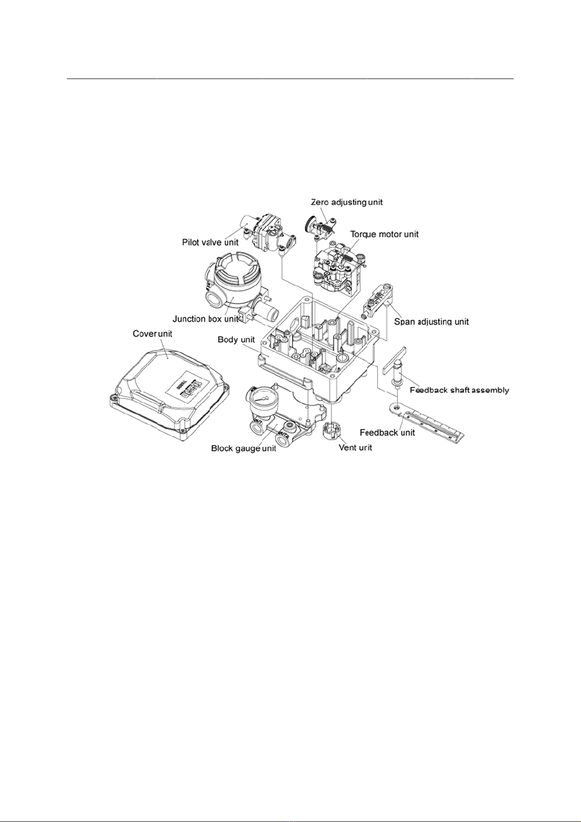
2.9 Parts and Assembly------------------------------------------------------------------------ 13
2.9.1 Standard type----------------------------------------------------------------------- 13
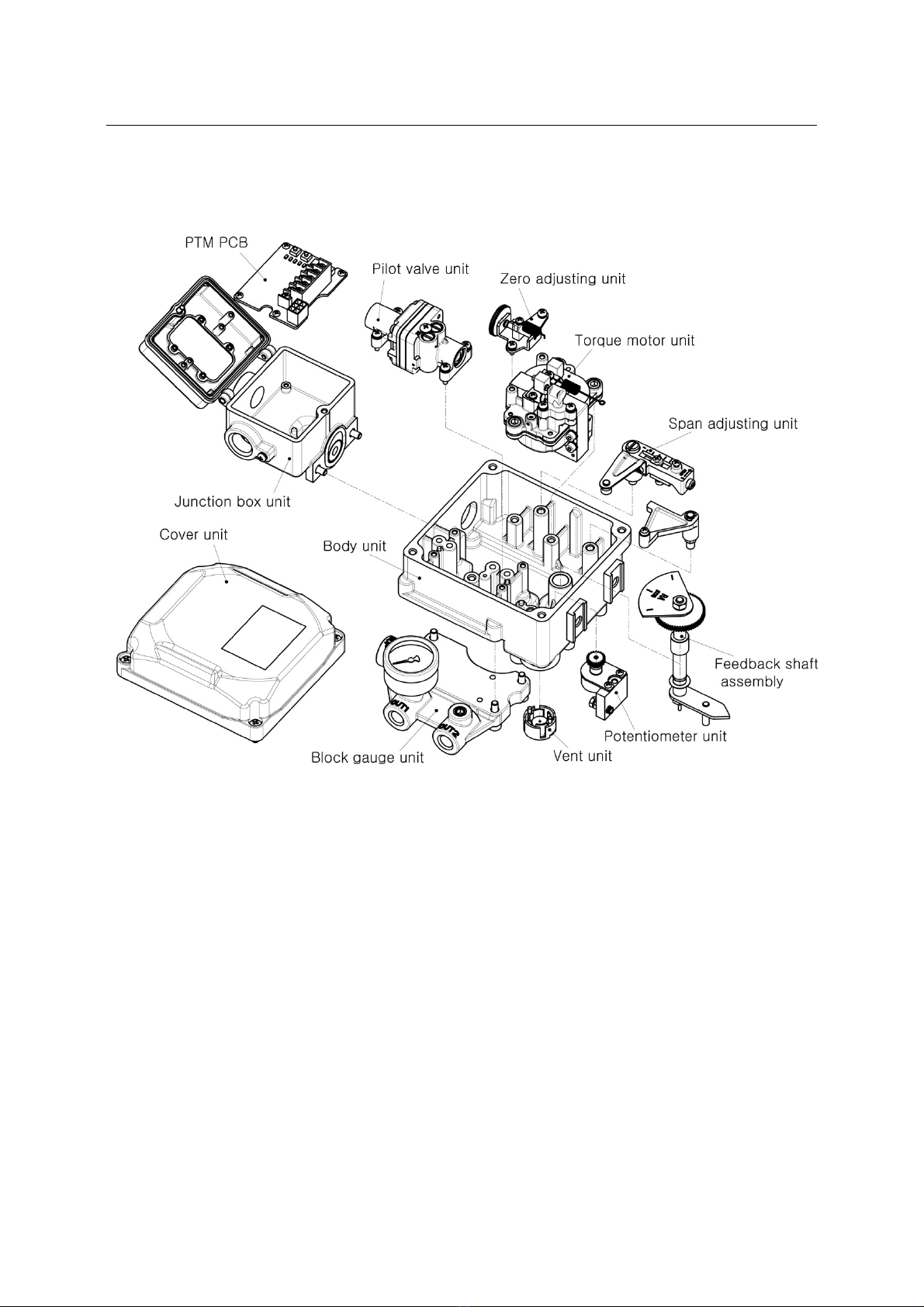
2.9.2 With Position transmitter type-------------------------------------------------- 14
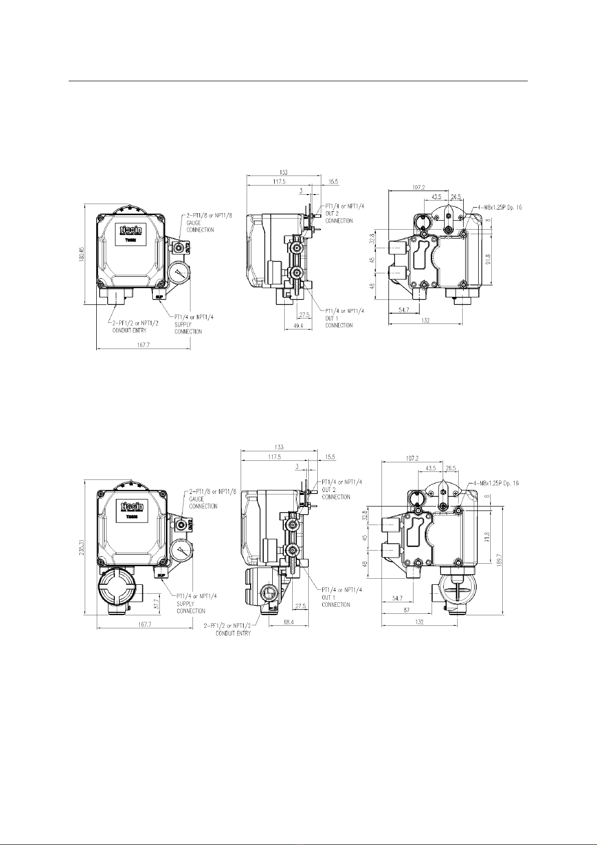
2.10 Dimension drawings----------------------------------------------------------------------- 15
2.10.1 TS600L Dimensions------------------------------------------------------------- 15
2.10.2 TS600R Dimensions------------------------------------------------------------ 17
3 Installation--------------------------------------------------------------------------------------- 19
3.1 Safety-------------------------------------------------------------------------------------------- 19
3.2 TS600L installation--------------------------------------------------------------------------- 19
3.3 TS600R installation--------------------------------------------------------------------------- 21
3.3.1 Fork lever type----------------------------------------------------------------------- 21

3
Electro-Pneumatic Positioner
TS600 Series tissin
3.3.2 NAMUR Type------------------------------------------------------------------------- 21
4 Air connection------------------------------------------------------------------------------- 22
4.1 Notice-------------------------------------------------------------------------------------------- 22
4.2 TS600L air connection----------------------------------------------------------------------- 22
4.3 TS600L RA/DA action setting------------------------------------------------------------- 22
4.4 TS600R air connection---------------------------------------------------------------------- 23
4.5 TS600R RA/DA action setting------------------------------------------------------------ 23
5 Power connection------------------------------------------------------------------------- 24
5.1 Flame proof type power connection------------------------------------------------------ 24
5.2 Intrinsically safe type power connection------------------------------------------------ 26
5.3 With Position transmitter------------------------------------------------------------------- 27
5.4 With Limit switch------------------------------------------------------------------------------ 28
5.5 With Position transmitter and Limit switch---------------------------------------------- 28
6 Adjustment-------------------------------------------------------------------------------------- 29
6.1 Zero and Span Adjustment----------------------------------------------------------------- 29
6.2 Position transmitter Setting(Option)------------------------------------------------------ 30
7 Troubleshooting---------------------------------------------------------------------------- 31
7.1 Common problems--------------------------------------------------------------------------- 31
7.2 Install orifice----------------------------------------------------------------------------------- 31
7.3 Adjust Potentiometer gear---------------------------------------------------------------- 32
7.4 Other problems and resolution------------------------------------------------------------ 33
8 Limited warranty and disclaimer -------------------------------------------- 34

4
Electro-Pneumatic Positioner
TS600 Series tissin
1 Introduction
1.1 General information for the user
This instruction includes installation, operation, maintenance, and parts information for Tissin
TS600 Valve Positioner. Keep these instructions in a location which is easily accessible to
every user and make these instructions available to every new owner of the device.
Installation, commissioning and maintenance of the product may only be performed by
trained specialist personnel who have been authorized by the plant operator to do so.
To avoid possible injury to personnel or damage to valve parts, WARNING, CAUTION
and NOTICE should be strictly followed.
Before installing or commissioning, be sure to read and thoroughly understand the
product manual and operate the product properly.
Operators must strictly observe the applicable national regulations with regards to
installation, function tests, repairs, and maintenance of electrical products.
For additional information or if specific problems occur that are not discussed in these
instructions, contact the manufacturer.
The manual can be altered or revised without any prior notice.
Please visit our website (http://www.tissin.co.kr ) check the latest documentation.
Manual version PM-TS600EN-12/2020
5
Electro-Pneumatic Positioner
TS600 Series tissin
1.2 Requirement for safety
This manual contains notices you have to observe in order to ensure your personal safety, as
well as to prevent damage to property. These safety instructions are intended to prevent
hazardous situations and/or equipment damage. For the safety, it is important to follow the
instructions in the manual.
WARNING Failure to observe the warning may result in serious injuries or death.
CAUTION Failure to observe this warning may result in product failure or injuries.
NOTICE Failure to observe this warning may result in product failure or performance
degradation.
Safety notes
CAUTION
Only trained and authorized person should operate machinery and equipment.
Do not use this positioner out of the range of its specifications as this can cause failure.
Do not service or attempt to remove product and machinery/equipment until safety is
confirmed.
Before loosening the pneumatic lines and valves, turn off the pressure and vent the
pneumatic lines.
Before reaching into the device or the equipment, switch off the power supply and
secure to prevent reactivation.
Observe applicable accident prevention and safety regulations for electrical equipment.
6
Electro-Pneumatic Positioner
TS600 Series tissin
1.3 Basic safety instructions for use in Ex area
To prevent the risk of explosion, observe not only the basic safety instructions in the
respective operating instructions for operation in the Ex area, but also the following.
WARNING
Observe the applicable safety regulations (also national safety regulations) as well as
the general rules of technology for construction and operation.
Make sure that the device is suitable for the area of use.
Check the positioner’s certified and permitted explosion proof range.
Close all unnecessary cable glands with lock screws approved for the explosions area.
TS600 series has 2 conduit entries. Flameproof cable must be used for cable entry,
and for unused cable entry, flameproof blind cable plug should be used.
TS600 series is certified under flame proof (Ex db mb IIB/IIC T6/T5 Gb).
Explosion proof zones 1 and 2.
1.4 Conditions to maintain intrinsic safety (Ex i)
WARNING
Connect the device with type of protection "Intrinsic safety" solely to an intrinsically
safe circuit.
Observe the specifications for the electrical data on the certificate and in technical
data.
TS600 series is certified under intrinsically safe (Ex ia IIC T6/T5 Gb).
Explosion proof zones 0, 1 and 2.
Intrinsic safety explosion standard
Explosion regulations IEC 60079-0:2017, IEC 60079-1:2014-06
IEC 60079-18:2017, IEC 60079-11:2011
Explosion proof Ex ia IIC T5/T6 Gb
Barrier specifications Ui li Pi
Main power 28V 101mA 707mW

7
Electro-Pneumatic Positioner
TS600 Series tissin
2 Description of products
2.1 Function
Electro-Pneumatic valve positioner TS600 series controls the valve stroke in response to an
input signal of 4~20mA DC from the control panel, DCS or calibrator.
2.2 Features
Applied to various control valve system
Fast response time, excellent stability and durability
Simple zero and span adjustment
IP 66 enclosure
Easy maintenance due to built-in module type
By-pass valve (A/M switch) installed
Air connection part is designed for detachability and it can be changed PT/NPT tapping
threads in the field easily
2.3 Options
Position transmitter(4~20mA DC Feedback signal)
Limit switch (Mechanical or Proximity type)
2.4 Applications
The TS600 is mounted on pneumatic control valves and is used for fluid control in industrial
parts.
Oil and gas
Chemicals
Power plant
Paper
Water treatment
Pharmaceutical
Printing and dyeing processing
Food and beverage
Etc.
Electr
o
TS600
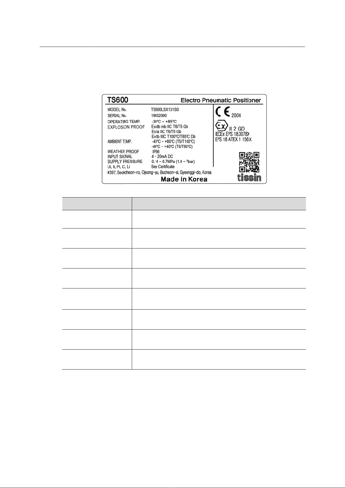
2.5
o
-Pneumati
c
Series
Label
Item
MODEL N
o
SERIAL N
o
OPERATI
N
EXPLOSI
O
AMBIENT
WEATHE
R
INPUT SI
G
SUPPLY
P
c
Positione
r
o
.
o
.
N
G TEMP
O
N PROOF
TEMP.
R
PROOF
G
NAL
P
RESSURE
r
Descri
p
Indicate
s
Indicate
s
Indicate
s
Indicate
s
Indicate
s
This te
m
explosi
o
Indicate
s
Indicate
s
Indicate
s
8
p
tion
s model nu
m
s serial num
s allowable
o
s certified e
x
s explosion
p
m
perature ra
n
o
n-proof are
a
s enclosure
s input sign
a
s supply pre
m
ber.
ber.
o
perating te
m
x
plosion pro
o
p
roof tempe
r
n
ge must be
a
s.
grade.
a
l range.
ssure range
.
m
perature.
o
f grade.
r
ature.
observed w
h
.
t
hen using in
issin

9
Electro-Pneumatic Positioner
TS600 Series tissin
2.6 Product Code
Model TS600
Acting Type Linear Type L
Rotary Type R
Explosion proof type Non-Explosion type N
Ex dmb IIB T5/T6
Ex dmb IIC T5/T6
B
C
Ex ia IIC T5/T6 A
ATEX & IECEx
Ex db mb IIB/IIC T6/T5 Gb
Ex ia IIC T6/T5 Gb
Ex tb IIIC T85℃/T100℃ Db IP66
X
Connection type Conduit Entry Air Connection
G(PF)1/2 PT1/4 1
G(PF)1/2 NPT1/4 2
NPT1/2 NPT1/4 3
M20
M20
NPT1/4
G1/4
4
5
Linear lever type 10~40mm 1
40~70mm 2
70~100mm 3
100~150mm 4
1
Rotary lever type M6 x 34L (Fork lever type)
NAMUR Type 5
Operating Temp. -20~70℃(Standard) S
-20~120℃* H
-40~70℃ L
Options* None 0
With Position transmitter (4~20mA)* 1
With Limit Switch * 2
With Limit Switch (Explosion proof type) 3
With Position transmitter and Limit Switch* 4
With Position transmitter and Limit Switch
(Explosion proof type)
5
With external Limit switch mounting device
With Position transmitter and external Limit switch
mounting device*
6
7
Note*
1. High temperature (-20℃~120℃) positioner must be Non-explosion proof type.
2. Options number 1, 2, 4, 7 must be Non-explosion proof type.

10
Electro-Pneumatic Positioner
TS600 Series tissin
2.7 Specification
2.7.1 Positioner
Model TS600L TS600R
Single Double Single Double
Input signal 4~20mA DC
Impedance 250±15Ω
Supply pressure 0.14~0.7MPa
Stroke 10~150mm 0~900
Air connection PT(NPT) 1/4
Gauge connection PT(NPT) 1/8
Conduit G(PF) 1/2 or NPT 1/2
Explosion proof type
Ex db mb IIB/IIC T6/T5 Gb
Ex ia IIC T6/T5 Gb
Ex tb IIIC T85℃/T100℃ Db
Degree of protection IP66
Ambient
Temp.
Operating Temp. -20℃∼70℃ (Standard),
-40℃∼70℃ (Low Temp.), -20℃∼120℃ (High Temp.)
Explosion proof
Temp. -40℃~60℃(T5/T100℃) / -40℃~40℃(T6/T85℃)
Linearity ±1.0% F.S ±2.0% F.S ±1.0% F.S ±2.0% F.S
Sensitivity ±0.2% F.S ±0.5% F.S ±0.2% F.S ±0.5% F.S
Hysteresis ±1.0% F.S
Repeatability ±0.5% F.S
Air consumption Below 2.5LPM (Sup=0.14MPa)
Flow capacity Over 80LPM (Sup=0.14MPa)
Material Aluminum die casting
Weight 2.8kg
2.7.2 Position transmitter (Option)
Item type Specification
Input voltage 9~30V DC
Output current 4~20mA DC
Connection type 2 Wire Type
Impedance Max.600Ω / 30V
Range of temperature -40℃∼85℃
Linearity ±1%
Sensitivity ±0.2%
Hysteresis 1%

11
Electro-Pneumatic Positioner
TS600 Series tissin
2.7.3 Limit Switch (Option)
Item type Specification
Switch type 2 x SPDT
Degree of protection IEC IP40
Rating (AC) 16A 1/2HP 125/250VAC
Rating (DC) 0.6A @ 125VDC, 0.3A @ 250VDC
Durability Min. 100,000 @ 30 operation / min
Temperature rating -25℃~80℃
Electric shock Class I
Position Indicator Open : Yellow , Close : Red
Electr
o
TS600
2.8
o
-Pneumati
c
Series
Operatio
n
The diaphr
a
Feedback
s
diaphragm
field streng
t
feedback t
h
* The dia
RA (Re
v
linear t
y
* Nozzle
the Fla
p
* Loop P
o
c
Positione
r
n
Logic
a
gm valve
m
s
pring throu
g
valve is bal
a
t
h generate
d
h
e moveme
n
grams abov
e
v
erse Actio
n
y
pe except f
e
back pressu
p
per.
o
sitioner an
d
r
m
oves down
w
g
h Feedbac
k
a
nced at the
d
by the inpu
n
t of the Pilot
<T
S
e
explanatio
n
) type. TS6
0
e
edback stru
re internal p
r
d
Control val
v
12
w
ard. The m
o
k
lever and F
position bet
w
t current. G
a
t
Valve to th
e
S
600L Oper
a
n
s based on
0
0R rotary ty
cture.
ressure of N
v
e consist o
f
o
vement of
d
lapper incre
a
w
een the ab
o
a
in suppress
e
Flapper an
d
a
tion logic>
TS600L lin
e
pe is same
a
ozzle depen
f
closed-circ
u
d
iaphragm v
a
a
ses torque
t
o
ve spring t
o
i
on spring is
d
it increase
s
e
ar type and
a
s Operation
ds on the c
o
u
it through F
e
t
a
lves acts o
n
t
o the left p
u
o
rque and m
a
used to im
m
s
the loop*
s
Diaphragm
v
logic of TS
6
o
ntrol the No
z
eedback lev
issin
n
ll. The
a
gnetic
m
ediately
tability.
v
alve of
6
00L
z
zle by
e
r.
Electr
o
TS600
2.9
2
o
-Pneumati
c
Series
Parts an
d
.9.1 Stan
d
c
Positione
r
d
Assemb
l
d
ard type
r
y
13
tissin
14
Electro-Pneumatic Positioner
TS600 Series tissin
2.9.2 With Position transmitter type

15
Electro-Pneumatic Positioner
TS600 Series tissin
2.10 Dimension Drawings
2.10.1 TS600L Dimensions
<TS600L Intrinsically safe type / Non-Explosion proof type Dimension>
<TS600L Flame proof type / ATEX & IECEx type Dimension >

16
Electro-Pneumatic Positioner
TS600 Series tissin
<TS600L with Position transmitter type Dimension>
17
Electro-Pneumatic Positioner
TS600 Series tissin
2.10.2 TS600R Dimensions
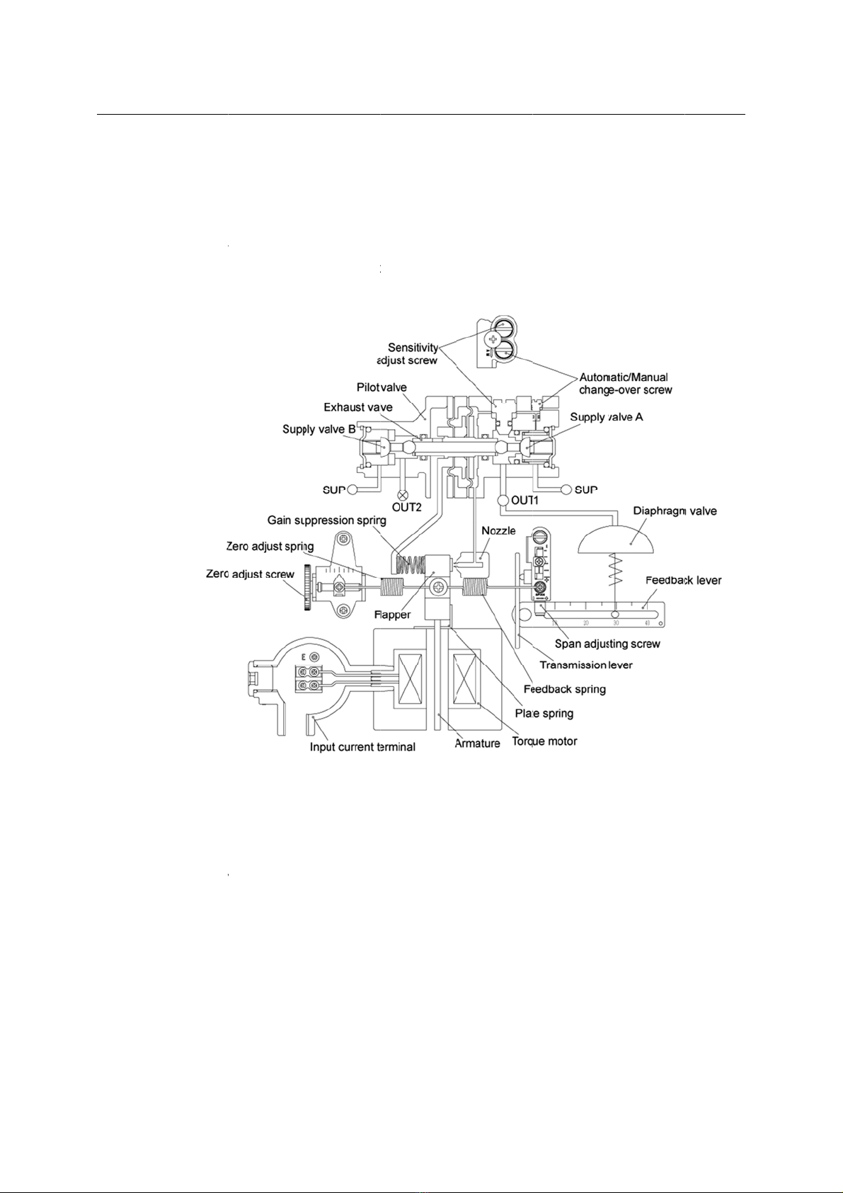
Operation Logic
When the input current (4-20mA) increases, Armature receives counter-clockwise rotating torque as a
magnetic field strength of Torque motor and Flapper moves to left as the center of Plate Spring. When
the space between Flapper and Nozzle opens, the Nozzle back pressure* decreases. As a result,
Exhaust valve of Pilot valve moves to right. At the same time, Supply valve A of OUT1 moves to right
and opens Supply valve. Air supply through OUT1 increases air pressure of diaphragm and
<TS600R Intrinsically safe type / Non-Explosion proof type Dimension>
<TS600R Flame proof type Dimension>
<TS600R Flame proof type Dimension>
<TS600R Flame proof type Dimensio
<TS600R Flame proof type / ATEX & IECEx type Dimension>

18
Electro-Pneumatic Positioner
TS600 Series tissin
<TS600R with Position transmitter type Dimension>
<TS600R with Limit switch type / with Position transmitter and Limit switch type Dimension>

Electr
o
TS600
3
3.1
3.2
o
-Pneumati
c
Series
Install
a
Safety
When inst
a
Make
a
Cut su
TS600L I
n
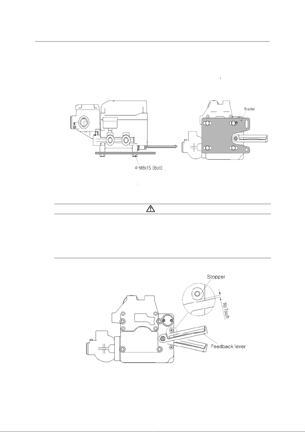
Proper bra
c
consider fo
Check
Feedb
a
a way
fitted.
<
c
Positione
r
a
tion
a
lling a positi
o
a
space nee
d
pply pressu
r
n
stallatio
n
<Fi
g
c
ket must b
e
llowing imp
o
if feedback
l
a
ck lever co
n
that the val
v
<
Figure2>
r
o
ner, please
d
ed for main
r
e and relea
s
n
g
ure 1>
e
made in o
r
o
rtant points
w
l
ever is para
n
nection wit
h
v
e stroke an
d
19
WA
R
e
ensure to r
e
n
tenance on
t
s
e compress
CA
U
r
der to ada
p
w
hen a bra
c
llel to the gr
o
h
the pin of
t
d
numbers
w
R
NING
e
ad and foll
o
t
he setting a
ed air in pos
U
TION
p
t the positio
c
ket is being
o
und at 50%
t
he actuator
c
w
hich indicat
e
o
w safety ins
t
rea.
itioner and
a
n
er on the
a
d
esigned.
of the valve
c
lamp shoul
d
e
d on the fe
e
t
t
ruction.
a
ctuator in a
d
<Figure 2>
a
ctuator yok
e
e
stroke. <Fi
g
d
be installe
d
e
dback leve
r
issin
d
vance.
e
. Please
g
ure 1>
d
in such
r
must be
Electr
o
TS600
o
-Pneumati
c
Series
TS600L br
a
A
ssemble
t
Please ref
e
M8 x 1.25
P
A
fter i
n
air to t
not to
u
If the f
e
from t
h
c
Positione
r
a
cket Instal
t
he position
e
e
r to the bac
k
P
.
<
n
stalling the
he actuator
u
ch the lever
e
edback lev
e
h
e yoke.
<TS60
0
r
lation
r with the br
a
k
side of the
p
TS600L Bra
positioner,
o
(manual po
s
stopper, wh
e
r touches t
h
L Feedback
20
a
cket made
p
ositioner fo
r
a
cket Installa
t
CA
U
o
perate the
v
s
ition). On b
o
ich is locate
d
h
e stopper, t
lever shoul
d
in previous
s
r
size of the
b
t
ion Exampl
e
U
TION
v
alve from 0
%
o
th 0% and
d
on the bac
he positione
d
not touch l
e
s
tep by faste
b
olts. The st
a
e
>
%
to 100%
s
100%, the f
e
kside of the
r
should be i
e
ver stopper
>
t
ning the bol
t
t
andard bolt
s
s
troke by us
i
e
edback lev
e
positioner.
i
nstalled furt
h
>
issin
t
s.
s
ize is
i
ng direct
e
r should
h
er away
This manual suits for next models
2
Table of contents
Other tissin Valve Positioner manuals


Popular Valve Positioner manuals by other brands

Soldo Controls
Soldo Controls IOM-RD00-03 Installation & operation manual

CVS Controls
CVS Controls YT-1000L product manual

halstrup-walcher
halstrup-walcher PS*3**Mod series instruction manual

Burkert
Burkert 8694 operating instructions

Festo
Festo CMSH operating instructions

YASKAWA
YASKAWA MH SIGMA-5 Series manual


Johnson Controls
Johnson Controls V-9502-76 quick start guide

Burkert
Burkert 8635 operating instructions

Spirax Sarco
Spirax Sarco SP7-10 Installation and maintenance instructions

Parker
Parker MX80L series product manual

Spirax Sarco
Spirax Sarco SP400 Installation and maintenance instructions

Bifold
Bifold IS200 Operation, installation, and maintenance manual