manuals.online logo
Brands
  1. Home
  2. •
  3. Brands
  4. •
  5. Samson
  6. •
  7. Valve Positioner
  8. •
  9. Samson 4785 Service manual

Samson 4785 Service manual

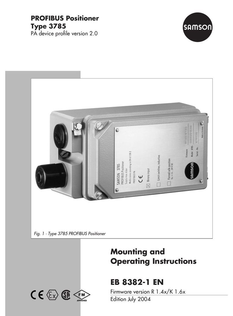
PROFIBUS Positioner
Type 3785
PA device profile version 3.0
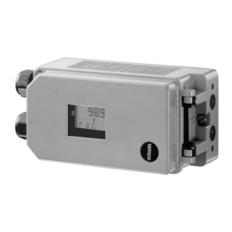
Fig. 1 ⋅Type 3785
Mounting and
operating instructions
EB 8382 2 EN
Firmware R 1.42/K 2.11
Edition Jan ary 2003
Contents Page
Safety instructions . . . . . . . . . . . . . . . . . . . . . . . . . . . . . . 4
Firmware modifications . . . . . . . . . . . . . . . . . . . . . . . . . . . 5
Technical data . . . . . . . . . . . . . . . . . . . . . . . . . . . . . . . . 8
Positioner versions . . . . . . . . . . . . . . . . . . . . . . . . . . . . . . 9
1. Design and principle of operation . . . . . . . . . . . . . . . . . . . . . . 10
1.1 Options . . . . . . . . . . . . . . . . . . . . . . . . . . . . . . . . . . . 10
1.2 Communication . . . . . . . . . . . . . . . . . . . . . . . . . . . . . . . 10
2. Attaching the positioner . . . . . . . . . . . . . . . . . . . . . . . . . . . 12
2.1 Direct attachment to Type 3277 ctuator . . . . . . . . . . . . . . . . . . . 12
2.2 ttachment according to IEC 60534-6 . . . . . . . . . . . . . . . . . . . . 16
2.2.1 Mounting sequence . . . . . . . . . . . . . . . . . . . . . . . . . . . . . 16
2.2.2 Presetting the valve travel . . . . . . . . . . . . . . . . . . . . . . . . . . . 18
2.3 ttachment to rotary actuators . . . . . . . . . . . . . . . . . . . . . . . . 20
2.3.1 Mounting the cam follower roll lever . . . . . . . . . . . . . . . . . . . . . 20
2.3.2 Mounting the intermediate piece . . . . . . . . . . . . . . . . . . . . . . . 20
2.3.3 ligning and mounting the cam disk . . . . . . . . . . . . . . . . . . . . . 22
2.3.4 Reversing amplifier for double-acting actuators . . . . . . . . . . . . . . . . 24
2.4 Fail-safe position of the actuator . . . . . . . . . . . . . . . . . . . . . . . 24
. Connections . . . . . . . . . . . . . . . . . . . . . . . . . . . . . . . . . 26
3.1 Pneumatic connections . . . . . . . . . . . . . . . . . . . . . . . . . . . . 26
3.1.1 Pressure gauge . . . . . . . . . . . . . . . . . . . . . . . . . . . . . . . 26
3.1.2 Supply air pressure . . . . . . . . . . . . . . . . . . . . . . . . . . . . . 27
3.2 Electrical connections . . . . . . . . . . . . . . . . . . . . . . . . . . . . 27
3.2.1 Forced venting . . . . . . . . . . . . . . . . . . . . . . . . . . . . . . . . 29
3.2.2 Limit switches . . . . . . . . . . . . . . . . . . . . . . . . . . . . . . . . 30
3.2.3 Establishing communication (bus address) . . . . . . . . . . . . . . . . . . . 30
3.2.4 Local interface (SSP) . . . . . . . . . . . . . . . . . . . . . . . . . . . . . 30
4. Operation . . . . . . . . . . . . . . . . . . . . . . . . . . . . . . . . . . 32
4.1 LED controls . . . . . . . . . . . . . . . . . . . . . . . . . . . . . . . . . 32
4.2 Write protection . . . . . . . . . . . . . . . . . . . . . . . . . . . . . . . 33
4.3 ctivating/deactivating the forced venting function . . . . . . . . . . . . . . 33
Contents
2EB 8382-2 EN
4.4 Default settings . . . . . . . . . . . . . . . . . . . . . . . . . . . . . . . 33
4.4.1 djusting mechanical zero . . . . . . . . . . . . . . . . . . . . . . . . . 34
4.4.2 Initialization . . . . . . . . . . . . . . . . . . . . . . . . . . . . . . . . 34
4.5 djusting the inductive limit switches . . . . . . . . . . . . . . . . . . . . 36
5. Maintenance . . . . . . . . . . . . . . . . . . . . . . . . . . . . . . . 37
6. Servicing explosion-proof versions . . . . . . . . . . . . . . . . . . . . . 37
7. How to implement the PROFIBUS Master Class 1 . . . . . . . . . . . . . . 38
7.1 Device Database Files (GSD) . . . . . . . . . . . . . . . . . . . . . . . . 38
7.2 Data exchange . . . . . . . . . . . . . . . . . . . . . . . . . . . . . . . 38
7.3 Parameter description . . . . . . . . . . . . . . . . . . . . . . . . . . . 42
7.4 Status code of the measured variable . . . . . . . . . . . . . . . . . . . . 44
7.5 Operating modes . . . . . . . . . . . . . . . . . . . . . . . . . . . . . 46
7.5.1 Start-up (warm start) . . . . . . . . . . . . . . . . . . . . . . . . . . . . 47
7.5.2 Monitoring function FS FE_TIME, FS FE_TYPE, FS FE _V LUE . . . . . . . 47
8. List of parameters . . . . . . . . . . . . . . . . . . . . . . . . . . . . . 50
9. Messages and diagnosis . . . . . . . . . . . . . . . . . . . . . . . . . . 66
9.1 Diagnosis messages . . . . . . . . . . . . . . . . . . . . . . . . . . . . 66
9.2 "CHECK_B CK" messages . . . . . . . . . . . . . . . . . . . . . . . . . 68
9.3 Initialization messages . . . . . . . . . . . . . . . . . . . . . . . . . . . 70
Dimensional diagram . . . . . . . . . . . . . . . . . . . . . . . . . . . 72
Certificates . . . . . . . . . . . . . . . . . . . . . . . . . . . . . . . . 73
Contents
EB 8382-2 EN 3
Safety instructions
The device may only be assembled, started up or operated by trained and ex-
perienced personnel amiliar with the product.
According to these mounting and operating instructions, trained personnel is
re erred to as individuals who are able to judge the work they are assigned to
and recognize possible dangers due to their specialized training, their knowl-
edge and experience as well as their knowledge o the applicable
standards.
Explosion-proo versions o this device may only be operated by personnel
who have undergone special training or instructions, or who are authorized to
work on explosion-proo devices in hazardous areas (also see section 6).
Any hazards which could be caused in the control valve by the process me-
dium, the operating pressure, the signal pressure or by moving parts are to be
prevented by means o the appropriate measures.
I inadmissible motions or orces are produced in the pneumatic actuator as a
result o the supply air pressure level, it must be restricted by means o a suit-
able pressure reducing station.
Proper shipping and appropriate storage are assumed.
Note! The device with a CE marking ul ils the requirements o the Directives
94/9/EC (ATEX) and 89/336/EEC (EMC).
The declaration o con ormity can be viewed and downloaded on the Internet at
http://www.samson.de.
4EB 8382-2 EN
Modifications in the positioner firmware compared to earlier version
Old New
Control R 1.23 R 1.31
Firmware adaption for new hardware version
Hardware version device index .01
Control R 1.31 R 1.4
ctuator type When the actuator type is set from "linear actuator" to "rotary
actautor", the following applies:
Initialization method ............Based on maximum range
Transmission code ...............S90
Nominal angle ....................90°
Final position for w <...........1 %
Final position for w >...........99 %
Rotat. angle range begins.....0°
Rotational angle range ends.90°
When the actuator type is set from "linear actuator" to "rotary
actautor", the following applies:
Attachment .........................Integral...............................According to NAMUR
Type of initialization.............Based on nominal range ......Based on nominal range
Mounting position................ rrow towards actuator ....... rrow away from actuator
Transmission code.................D1 ......................................
Pin position...................................................................
Rated travel..........................15 mm ................................15 mm
Final position for w < ............1 %.....................................1 %
Final position for w > ............125 %.................................125 %
Lower travel range value........0 mm ..................................0 mm
Upper travel range value.......15 mm ................................15 mm
Lever length...................................................................42 mm
Type of initialization When the initialization method is set from "maximum range" to
"nominal range", the following applies:
Final position for w < 1 % Final position for w > 125 %
When the initialization method is set from "maximum range" to
"nominal range", the following applies:
Final position for w < 1 % Final position for w > 99 %
Desired transit time
Open/Closed
The adjustment range of the desired transit times was limited to
75 seconds.
Initialization During initialization, the minimum control signals from 20 % to
80 % of the range of the manipulated variable are determined
and saved in the EEPROM.
Firmware modifications
EB 8382-2 EN 5
Proportional-action
coefficients
KP_Y1 and KP_Y2
The coefficients are adapted to the selected actuator type and
the measured transit times.
Control R 1.41 R 1.4.2
Correction in case of zero adjustment triggered via
communication.
Communication K 1.34 K 1.41
Firmware adaption for new hardware version
Hardware version device index .01
Communication K 1.41 K 1.51
The current status of control loop monitoring is indicated by
bit 7 of the CHECK_B CK parameter. Contrary to bit 13, bit 7
is automatically reset when no further error is detected by
control loop monitoring. The function of bit 13 remains
unchanged. Messages are only issued by bit 7 if control
firmware version R 1.41 or higher is used.
The message "Warm start" indicated by bit 11 of the
DI GNOSIS parameter is automatically reset after 10 sec.
In operating mode "Local override", bit 2 of the CHECK_B CK
parameter is set.
Communication K 1.51 K 1.60
In operating mode "Manual", the out value is preset by the
parameter OUT.
Communication K 1.60 K 2.00
This firmware version implements the PROFIBUS PA Profile .0,
Class B for control valves according to PROFIBUS P Profile for
Process Control Devices Version 3.0- ctuator.
The positioner can be connected to the TROVIS-VIEW
Configuration and Operator Interface via the serial interface for
adjustment and operation.
Firmware modifications
6EB 8382-2 EN
Communication K 2.00 K 2.10
When a zero point error or self-resetting control loop error
(transit time exceeded) is detected, or when the limit value for
the total valve travel is exceeded, the status of the parameters
RE DB CK or POS_D is set to
GOOD_M INTEN NCE_REQUIRED.
Firmware modifications
EB 8382-2 EN 7
Tec nical data
Positioner
Rated travel
Direct attachment to Type 3277
ttachment acc. to IEC 60534-6
(N MUR)
djustable
7.5 to 30 mm
7.5 to 120 mm
Or 30° to 120° for rotary actuators
Bus connection Fieldbus interface according to IEC 61158-2
Field unit according to FISCO (Fieldbus Intrinsically Safe COncept)
Permissible operating voltage 9 to 32 V DC

, supplied by bus connection
Static destruction limit 35 V
Maximum operating voltage 10 m
Current in case of fault 0 m
Supply air Supply air 1.4 to 6 bar (20 to 90 psi) ir quality according to ISO 8573-1:
Max. par ticle size and density: Class 2, Oil concentration: Class 3.
The pressure dew point must be 10 °C below the lowest ambient temperature
value to be expected
Signal pressure (output) 0 bar to supply air pressure
Characteristic, adjustable Linear, equal percentage, reverse equal percentage, freely programmable
Deviation from characteristic
≤1 %
Dead band
(based on rated travel/nom. angle)
djustable from 0.1 to 10.0 % , default 0.5 %
Resolution <0.05 % (internal measurement)
Transit time Up to 240 sec, separately adjustable for exhaust and supply air
Operating direction Reversible, adjustable using software
ir consumption Independent of supply air <90l

/h
ir supply ctuator filled: at
∆p = 6 bar 9.3 m

/h, at ∆p = 1.4 bar 3.5 m

/h
ctuator vented: at
∆p = 6 bar 15.5 m

/h, at ∆p = 1.4 bar 5.8 m

/h
Permissible ambient temperature 40 to 80 °C; the values of the EC Type Examination Certificate apply
additionally for explosion-proof devices
Effects Temperature: ≤0.15 %/10 K, auxiliary power: none,
Vibration: none up to 250 Hz and 4 g
Explosion protection II 2 G EEx ia IIC T6 according to TEX, see type examination certificate
Degree of protection IP 65 achieved by enclosed filter check valve
Electromagnetic compatibility Complies with requirements as in EN 50081/50082
Binar y input Internal power supply 5 V DC, R

= 100 kΩ
For signaling function, e.g. connection of a pressure switch
Forced venting,
to be activated via switch inside the
positioner
Input: 6 to 24 V DC, static destruction limit 45 V, R

approx. 6 kΩat 24 V DC
(depending on voltage), switching point 1- signal at
≥ 3V, 0- signal only at 0 V,
Kv value 0.17
8EB 8382-2 EN
Communication Data transfer according to PROFIBUS P Profile, Class B, Version 3.0 according to
DIN EN 50170 and DIN 19245 Part 4 (version 2.0 also available)
Local interface S MSON SSP inter face for configuration and start-up
Bus address djustable using software or microswitch, delivered as 126
Accessories
Inductive limit switches Two proximity switches SJ 2 SN for connection to switching amplifier according to
EN 50227
Materials
Body Die-cast aluminum, chromated and plastic-coated
External parts Stainless steel 1.4571 and 1.4301
Weight pprox. 1.3 kg

For the intrinsically safe version 3785-1..., the data given in the type examination certificate apply (see ppendix)
Versions
Positioner versions
Model 785 - XXXXX X
Explosion protection Without
II 2 G EEx ia IIC T6 acc. to TEX
With Ex ia CS /FM
0
1
ccessories Limit switches Without
2 inductive
0
22
Forced venting Without
With
0
12
P device profile Version 2.0
Version 3.0
0
1
Pneumatic
connections
NPT 1/4- 18
ISO 228/1- G1/4
1
2
Electric connections Cable gland M 20 x 1.5 with
shield, nickel-plated brass
Number: 1
Number: 2
1
2
EB 8382-2 EN 9
1. Design and principle of oper-
ation
The digital PROFIBUS P positioner is at-
tached to pneumatic control valves. It as-
signs the valve position (controlled variable)
to the control signal (reference variable).
The positioner compares the digital control
signal transmitted from the control equip-
ment to the travel of the control valve and
issues a pneumatic signal pressure (output
variable). To do so, a supply air pressure of
1.4 to 6 bar is required. The electric power
is supplied by the bus connection of the
PROFIBUS P segment in accordance with
IEC 61158-2 regulations.
The positioner consists of an inductive, fric-
tionless displacement sensor system and an
electrically controlled valve block with two
on-off valves, as well as the electronics in-
cluding the two microcontrollers to edit the
control algorithm and manage PROFIBUS
communication.
When a system deviation occurs while com-
paring set point and actual value, the micro-
controller returns binary pulse-pause-modu-
lated signals which are used to control two
on-off valves with subsequent boosters. One
valve controls the exhaust air, the other the
supply air.
The supply air valve (3) connects the supply
air (7, supply air pressure 1.4 to 6 bar) and
the actuator (filling). The exhaust air
valve (4) connects the actuator and the at-
mosphere (venting). These on-off valves can
either have the switching states continuously
open or continuously closed, or they can
generate single pulses of variable width.
Controlling the two valves causes the actua-
tor of the control valve to move the plug
stem to a position corresponding to the ref-
erence variable. If there is no system devia-
tion, both the exhaust and supply air valves
are closed.
By default, the positioner is equipped with a
binary input for floating contacts, which
serves to signalize the switching state of an
additional field device via PROFIBUS.
The write protection switch in the hinged
cover (located near the bus address adjust-
ment) prevents that positioner settings are
overwritten via PROFIBUS communication
on activation.
Positioner with forced venting function:
The positioner is controlled by a 6 to 24 V
signal, causing the signal pressure to be ap-
plied to the actuator. When this voltage sig-
nal decreases, the signal pressure is shut off
and the actuator is vented. dditionally, the
control valve is moved to its fail-safe posi-
tion by the integrated springs.
ll positioners are equipped with the forced
venting function, which can be activated
and deactivated using a switch (also see sec-
tion 4.3).
1.1 Options
The standard positioner version can be sup-
plemented with limit switches. Two
proximity switches suitable for fail-safe cir-
cuits can be used to signalize the valves
final positions.
1.2 Communication
The positioner is completely controlled via
digital signal transmission according to
PROFIBUS P Profile Class B based on
DIN EN 50170 and DIN 19245 Part 4.
Data is transmitted as bit synchronous cur-
rent modulation with a transfer rate
10 EB 8382-2 EN
Design and principle of operation
of 31.25 kbps using twisted-pair cables as
specified in IEC 61158-2. The positioner set-
tings are usually adjusted with a PC. By
using a segment coupler, one or more posi-
tioners can be connected to the PCs
PROFIBUS segment.
fter mechanically setting the positioner to
zero, it can be automatically started up by
an initialization procedure. During this in-
itialization, zero is adjusted automatically
and the preset span is checked.
The positioner is delivered with a standard
configuration for a control valve with a
rated travel of 15 mm, designed for integral
positioner attachment. The positioner can
be individually configured to adapt it to
other actuators only by means of communi-
cation.
Configuration
The positioner is configured and operated
from the PC via the SSP interface (13) using
TROVIS-VIEW. lternatively, a segment
coupler can be used together with, for
example, the COMMUWIN II interface by
Endress + Hauser or the SIM TIC PDM soft-
ware by SIEMENS.
During configuration, you can enter par-
ameters such as characteristic, operating di-
rection, travel limitation, travel range, tran-
sit time and fault message.
Fig. 2 ⋅Functional diagram
11 10
1
12
ep
3
4
2
5
9
7
61
G
µC
61158-2
IEC
ep
G
µC
PROFIBUS-PA
8
Serial Interface
13
Supply air
Exhaust air
Binary input
Forced venting 1 Inductive displacement sensor
2 Microcontroller
3 On-off valve for supply air
4 On-off valve for exhaust air
5 Microcontroller
6 Switch for bus address and
write protection
7 Binary input
8 Forced venting
9 IEC 61158-2 interface
module
10 ctuator stem
11 Lever
12 Clamp
13 SSP interface
EB 8382-2 EN 11
Design and principle of operation
2. Attaching the positioner
The positioner can be attached either di-
rectly to the S MSON Type 3277 ctuator,
or according to N MUR (IEC 60534-6) to
control valves with casted or rod-type yokes.
In combination with an intermediate piece,
the device can also be attached to rotary ac-
tuators as rotary positioner.
s the positioner unit is delivered without
accessories, refer to the appropriate tables
for the order numbers of the required
mounting parts.
Note!
The positioner does not have its own vent
plug. The air is exhausted via vent plugs lo-
cated on the accessories (also see Figs. 3, 5
and 7).
Each positioner comes with a ilter check
valve or the exhaust air located below the
transparent protective cap on the back o
the positioner. The standard vent plug avail-
able as an accessory must be replaced with
this ilter check valve to achieve degree o
protection IP 65 protecting the device
against dirt and moisture.
2.1 Direct attachment to
Type 277 Actuator
For selection of the required mounting
parts, refer to Tables 1, 2 and 3 on
page 15.
When looking onto the signal pressure con-
nection or the switchover plate (120 cm2 ac-
tuator) from the top, the positioner is to be
attached to the left side of the actuator.
The arrow on the black case cover (Fig. 11)
must point towards the diaphragm cham-
ber.
Exception: Control valves in which the plug
only closes the seat area when the actuator
stem retracts. In this case, the positioner has
to be attached to the right side of the yoke
with the arrow pointing away from the dia-
phragm chamber.
1. Screw the clamp (1.2) to the actuator
stem, ensuring that the fastening screw
is located in the groove of the actuator
stem.
2. Screw associated lever D1 or D2 (for
700 cm2 actuator) to the transmission
lever of the positioner.
3. ttach distance plate (15) with the seal
pointing towards the actuator yoke.
4. Place positioner onto the plate so that
the lever D1 or D2 slides centrically
over the pin of the clamp (1.2). Screw
positioner to distance plate (15).
5. Mount the cover (16).
240, 50 and 700 cm2 actuators
6. lign the lateral switch plate at the con-
nection block (Fog. 3) with the arrow
12 EB 8382-2 EN
Attac ing t e positioner
Fig. 3 ⋅Attachment and signal pressure connection or Types 3277 (top) and 3277-5 Actuators with 120 cm
(bottom)
SUPPLY
1.2
D2
D1
15
16
15
1.2
16
Actuator stem retracts
Internal signal pressure
connection Signal pressure
connection over piping
1.2 Clamp
D1 Lever
D2 Lever
15 Distance plate
16 Cover
Signal pressure bore
Side view of connection
block with switch plate
Connection block
Marking
Marking
Symbol " ctuator
stem extends"
" ctuator stem
retracts"
Switchover plate
Switchover plate
Signal ressure input
Signal pressure input with
brass throttle, if required
Actuator stem extends
Venting
ctuator stem
extends
ctuator stem
retracts
EB 8382-2 EN 13
Attac ing t e positioner
symbol on the block. This means, the
adjusted symbol for " ctuator stem ex-
tends" or " ctuator stem retracts" must
match the actuator version used.
If necessary, remove the two fastening
screws and switch plate, turn the plate
by 180° and remount it.
7. Place the connection block with its seal-
ing rings against the positioner and ac-
tuator yoke, and screw it tight using the
fasting screw.
For actuators with fail-safe action " ctu-
ator stem retracts" additionally install
the prefabricated signal pressure tube
between connection block and actuator.
120 cm2 Actuator
For Type 3277-5 ctuators with 120 cm2,
the signal pressure is transmitted to the dia-
phragm chamber via the switchover plate
(Fig. 3, bottom).
Note!
For a rated travel o 7.5 mm, a brass
throttle (see table Accessories on page 15)
must be pressed into the seal located in the
signal pressure input on the actuator yoke.
With 15 mm rated travel, this is only re-
quired i the supply pressure exceeds 4 bar.
6. Remove the screw at the back of the po-
sitioner and close the signal pressure
output (output 38) at the side with the
associated plug included in the acces-
sory kit.
7. Mount the positioner so that the bore in
the distance plate (15) is aligned with
the seal located in the bore of the actua-
tor yoke.
8. lign the switchover plate with the
corresponding symbol for attachment
on the left side, and screw the plate to
the actuator yoke.
Note!
I , in addition to the positioner, a solenoid
valve or a similar device is attached to the
120 cm2 actuator, the rear M3 screw must
not be removed. In this case, the signal pres-
sure has to be ed rom the signal pressure
output to the actuator via the required con-
necting plate (see Table 2). The switchover
plate is no longer required.
Note! ( or all actuators)
For aster control valves with a transit time
< 0.6 sec., replace the ilter in the signal
pressure output (output 38) with a screw-in
throttle (see table Accessories), i necessary,
to improve the control properties.
Filling the spring chamber with air
If the spring chamber of the Type 3277 c-
tuator must be filled with the air exhausted
from the positioner, the spring chamber (ver-
sion " ctuator stem extends") can be con-
nected to the connection block by means of
a tube (Table 3). To do so, remove the vent
plug on the connecting block.
With Type 3277-5, version " ctuator stem
retracts", the air exhausted from the posi-
tioner is constantly applied to the spring
chamber via an internal bore.
14 EB 8382-2 EN
Attac ing t e positioner
Tab le 1
Required lever with associated clamp and distance plate
ctuator size
cm

Mounting kit
Order no.
D1 (33 mm in length with clamp 17 mm in height) 120 (G1/4)
120 (NPT 1/4)
1400-6790
1400-6791
D1 (33 mm in length with clamp 17 mm in height) 240 and 350 1400-6370
D2 (44 mm in length with clamp 13 mm in height) 700 1400-6371
Tab le 2 Order no.
Switchover plate for 120 cm

actuator ctuator 3277-5xxxxxx.
00 (old) 1400-6819
Switchover plate new ctuators with index .
01 (new) and higher 1400-6822
Connecting plate for additional
attachment e.g. of a solenoid valve
3277-5xxxxxxxx.
00
(old)
G 1/8
NPT 1/8
1400-6820
1400-6821
Connecting plate new ctuators with index .
01 (new) 1400-6823
Note! The new actuators (index 01) can only be used with new switchover and connecting plates. Old and new plates
are not interchangeable.
Connection block required for actuator sizes 240, 350 and 700 cm

(including seals and fastening screw)
G thread 1400-6955
NPT thread 1400-6956
Tab le ctuator size cm

Material Order no.
Required tubes including fittings
for actuator:
" ctuator stem retracts"
or
for filling the upper diaphragm chamber
240 Steel 1400-6444
240 Stainless steel 1400-6445
350 Steel 1400-6446
350 Stainless steel 1400-6447
700 Steel 1400-6448
700 Stainless steel 1400-6449
Accessories Order no.
Pressure gauge mounting kit for supply air and signal pressure SS/Brass
SS/SS
1400-6957
1400-6958
Signal pressure throttles (screw-in type and brass throttle) 1400-6964
Filter check valve, replaces exhaust air plug and increases the degree of protection to IP 65
(one included with the delivered positioner)
1790-7408
EB 8382-2 EN 15
Attac ing t e positioner
2.2 Attachment according to
IEC 605 4-6
For selection of the required mounting
parts, refer to Tables and 5 on page 19.
For positioner attachment according to
N MUR as shown in Fig. 4, an adapter
housing is required. The valve travel is trans-
mitted via the lever (18) and the shaft (25)
to the bracket (28) of the adapter housing
and then to the pin (27) located at the posi-
tioner lever.
To attach the positioner, the mounting parts
listed in Table 4 are required. Which lever is
to be used depends on the rated valve travel.
The positioner must be attached with the
arrow on the black case cover pointing
away from the diaphragm actuator to-
wards the valve.
Exception: Control valves in which the plug
only closes the seat area when the actuator
stem retracts. In this case, the arrow has to
point towards the diaphragm actuator.
If the adapter housing cannot be mounted
between the actuator and the valve (e.g. ac-
tuators by other manufacturers), the arrow
on the case cover must point towards the
control valve.
2.2.1 Mounting sequence
Note!
Be ore you mount the parts, apply a signal
pressure to the actuator so that the valve is
set to 50 % o its travel. This will ensure the
exact alignment o the lever (18) and the
bracket (28).
Control valve with casted yoke
1. Use countersunk screw to attach the
plate (20) to the coupling which con-
nects the plug and actuator stems. With
2100 and 2800 cm2 actuators, use ad-
ditional mounting bracket (32).
2. Remove rubber plug from the adapter
housing and fasten the housing to the
N MUR rib using the hexagon head
screw.
Control valve with rod-type yoke
1. Screw plate (20) to the follower clamp
of the plug stem.
2. Screw studs (29) into the adapter
housing.
3. Place the housing with the plate (30) on
either the right or the left side of the
valve rod and screw the housing tight
using nuts (31). Be sure to align the
housing in such a way that the lever to
be mounted subsequently is in a hori-
zontal position.
4. Move the clamp (21) to surround the
pin (19). Screw pin into the center row
of bores in the plate (20) and lock it
such that it will be located above the
correct lever marking (1 to 2) for the as-
signed travel (see Table 5).
Intermediate values must be calculated.
5. Measure the distance between the cen-
ter of the shaft (25) and the center of
the pin (19). You will be prompted for
this value later during the configuration
of the positioner.
16 EB 8382-2 EN
Attac ing t e positioner
Fig. 4 ⋅Attachment according to IEC 60534-6 (NAMUR)
2
1,5
1
2826
AB
24 25 22
32
31
20 19
19 21 2023 18
27b
27a
29
30
ttachment to
N MUR rib
Mounting position
ttachment to rods
18 Levers N1, N2
19 Pin
20 Plate
21 Clamp
22 Clamping plate
23 Screw
24 Pointer
25 Shaft
26 Lever of positioner
27a Transmisison pin
27b Lock nut
28 Bracket
29 Studs
30 Plate
31 Nuts
32 Mounting bracket
EB 8382-2 EN 17
Attac ing t e positioner
2.2.2 Presetting the valve travel
1. djust the shaft (25) in the adapter
housing so that the black pointer (24) is
aligned with the casted marking on the
adapter housing.
2. Screw clamping plate (22) tight in this
position using a screw (23).
3. Screw in the pin (27) at the positioner
lever (26) on the side of the insert nuts
and secure it with a hex nut on the op-
posite side. Note the mounting position
A or B respectively according to
Table 5 and Fig. 5.
4. Put the positioner to the adapter hous-
ing such that the pin (27) lies properly
within the arms of the bracket (28).
To do so, insert a 2.5 mm llen key or
a screwdriver from the front into the
bore located below the oblong hole on
the cover plate, and push the positioner
lever in the required position.
5. Screw the positioner to the adapter
housing.
6. Relieve the actuator from the signal
pressure.
18 EB 8382-2 EN
Attac ing t e positioner
Ta ble 4 N MUR attachment Control valve Travel in mm With lever Order no.
N MUR mounting kit
Parts, see Fig. 4
Valve with casted yoke
7.5 to 60 N1 (125mm) 1400-6787
30 to 120 N2 (212 mm) 1400-6789
Valve with
rod-type
yoke, rod
diameter in
mm
20 to 25 N1 1400-6436
20 to 25 N2 1400-6437
25 to 30 N1 1400-6438
25 to 30 N2 1400-6439
30 to 35 N1 1400-6440
30 to 35 N2 1400-6441
ttachment to Fisher and Masoneilan linear actuators
(one each of both mounting kits is needed per actuator)
1400-6771
and
1400-6787
Accessories Order no.
Pressure gauge mounting block G 1/4
NPT 1/4
1400-7106
1400-7107
Pressure gauge set SS/Brass
SS/SS
1400-6957
1400-6958
Signal pressure throttles (screw-in type and brass throttle) 1400-6964
Filter check valve, replaces exhaust air plug and increases the degree of protection to IP 65
(one included with the delivered positioner)
1790-7408
Ta ble 5 N MUR attachment
Travel in mm *) 7.51515303060306060120
Pin on marking *) 1 12121212
Corresp. distance pin/lever fulcrum 42 42 84 42 84 84 168 84 168
With lever N1 (125 mm in length) N2 (212 mm in length)
Transmission pin (27) on position B B
*) Deviating travel values (intermediate values) must be calculated accordingly
EB 8382-2 EN 19
Attac ing t e positioner
2. Attachment to rotary actuators
For selection of the required mounting
parts, refer to Table 6 on page 23.
The positioner can also be attached to rot-
ary actuators according to VDI/VDE 3845
by using the mounting parts and acces-
sories listed in Table 6. In this arrange-
ment, the actuators rotary motion is con-
verted via the cam disk on the actuator
shaft and the follower roll of the positioner
lever into a linear motion required by the
positioners inductive displacement sensor
system.
Each cam disk is suitable for two curves: for
angles of rotation from 0 to 90° and for
0 to 120°.
For double-acting, springless rotary actua-
tors, it is necessary that a reversing ampli-
fier be attached to the connected side of the
positioner (see section 2.3.4).
If the positioner is attached to s S MSON
Type 3278 Rotary ctuator, the air ex-
hausted from the positioner is transferred to
the inside of the actuator and the chamber
behind the diaphragm. No additional tub-
ing is required.
If the positioner is attached to actuators by
other manufacturers (N MUR), the air is ap-
plied to the chamber behind the diaphragm
through a tube assembly with tee, con-
nected between actuator and intermediate
piece.
2. .1 Mounting the cam follower
roll lever
1. Place lever with the attached roll (35)
on the transmission lever (37) and se-
cure it with the enclosed screws (38)
and washers.
2. .2 Mounting the intermediate piece
SAMSON Type 278 Actuator:
1. Screw adapter (36) to the free end of
the rotary actuator shaft using two
screws.
2. Position intermediate piece (34) on the
actuator case and secure it with two
screws. lign the positioners intermedi-
ate piece so that the air connections of
the positioner face towards the dia-
phragm case side.
Actuators by other manufacturers:
1. Position complete intermediate piece
(34, 42 and 44) on fixing level 1 of the
bracket (VDI/VDE 3845) delivered with
the actuator and fasten with screws.
2. lign cam disk (40) and scale as de-
scribed in section 2.3.3. Fasten with
screws.
With springless actuators, the reversing
amplifier (45) must be screwed to the
side of the positioner case. See sec-
tion 2.3.4 for more details.
20 EB 8382-2 EN
Attac ing t e positioner

Other Samson Valve Positioner manuals

Samson 3730-2 User manual

Samson

Samson 3730-2 User manual

Samson 3730-0 Service manual

Samson

Samson 3730-0 Service manual

Samson 3730-2 Service manual

Samson

Samson 3730-2 Service manual

Samson 4765 Service manual

Samson

Samson 4765 Service manual

Samson TROVIS SAFE 3730-6 Service manual

Samson

Samson TROVIS SAFE 3730-6 Service manual

Samson TROVIS SAFE 3731-3 Service manual

Samson

Samson TROVIS SAFE 3731-3 Service manual

Samson TROVIS 3730-3 Service manual

Samson

Samson TROVIS 3730-3 Service manual

Samson 3730-0 Service manual

Samson

Samson 3730-0 Service manual

Samson 3731-5 Service manual

Samson

Samson 3731-5 Service manual

Samson 3785 series Service manual

Samson

Samson 3785 series Service manual

Samson 3730 Series Service manual

Samson

Samson 3730 Series Service manual

Samson TROVIS 3730-1 User manual

Samson

Samson TROVIS 3730-1 User manual

Samson TROVIS 3731-3 Service manual

Samson

Samson TROVIS 3731-3 Service manual

Samson Type 3766 Service manual

Samson

Samson Type 3766 Service manual

Samson 3761 Service manual

Samson

Samson 3761 Service manual

Samson 3780 series Service manual

Samson

Samson 3780 series Service manual

Samson 3731-5 Service manual

Samson

Samson 3731-5 Service manual

Samson TROVIS 3730-3 Service manual

Samson

Samson TROVIS 3730-3 Service manual

Samson 4763 Service manual

Samson

Samson 4763 Service manual

Samson 4763 Service manual

Samson

Samson 4763 Service manual

Samson FOUNDATION 3730-5 Service manual

Samson

Samson FOUNDATION 3730-5 Service manual

Samson TROVIS 3793 User manual

Samson

Samson TROVIS 3793 User manual

Samson 373 Series User manual

Samson

Samson 373 Series User manual

Samson 3730 Series Service manual

Samson

Samson 3730 Series Service manual

Popular Valve Positioner manuals by other brands

ERIKS ECON 3300 NCS Series Installation & operating manual

ERIKS

ERIKS ECON 3300 NCS Series Installation & operating manual

Lincoln Electric POSIMATIC PS03 Safety instruction for use and maintenance

Lincoln Electric

Lincoln Electric POSIMATIC PS03 Safety instruction for use and maintenance

OMC RE20 Installation, operation and maintenance manual
OMC

OMC RE20 Installation, operation and maintenance manual

Aventics R431004052 Service information

Aventics

Aventics R431004052 Service information

ABB HART Industrial IT enabled TZIDC operating instructions

ABB

ABB HART Industrial IT enabled TZIDC operating instructions

Waycon SX300 Series manual

Waycon

Waycon SX300 Series manual

DeZurik P200 Installation,operation and maintenance instruction

DeZurik

DeZurik P200 Installation,operation and maintenance instruction

Baker Hughes Becker Series instruction manual

Baker Hughes

Baker Hughes Becker Series instruction manual
Power-Genex SS3L Series Instructions and operating manual

Power-Genex

Power-Genex SS3L Series Instructions and operating manual

Festo CMSX-P-S-A1-C-U-F1-D series operating instructions

Festo

Festo CMSX-P-S-A1-C-U-F1-D series operating instructions

CVS Controls YT-1000L product manual

CVS Controls

CVS Controls YT-1000L product manual

Leuze electronic BPS 34 Technical description
Leuze electronic

Leuze electronic BPS 34 Technical description

Baker Hughes Masoneilan SVI FF quick start

Baker Hughes

Baker Hughes Masoneilan SVI FF quick start

halstrup-walcher PS*3**C series instruction manual

halstrup-walcher

halstrup-walcher PS*3**C series instruction manual

HART VVP10-H INSTALLATION, OPERATION, CONFIGURATION AND MAINTENANCE MANUAL

HART

HART VVP10-H INSTALLATION, OPERATION, CONFIGURATION AND MAINTENANCE MANUAL

Val Controls IHP24-A user manual

Val Controls

Val Controls IHP24-A user manual

Flowserve Logix 3000MD Series Technical bulletin

Flowserve

Flowserve Logix 3000MD Series Technical bulletin

Baileigh WP-1100 Operator's manual

Baileigh

Baileigh WP-1100 Operator's manual

manuals.online logo
manuals.online logoBrands
  • About & Mission
  • Contact us
  • Privacy Policy
  • Terms and Conditions

Copyright 2025 Manuals.Online. All Rights Reserved.