FibroLAN S.CON1M/MA Manual

1
S.CON1M/MA System
Managed Single Channel
10/100BaseTX-FX Media Converter
User and Installation Guide
Version: 1.3
FibroLAN Ltd
Yokneam Star Building, P.O. Box 544, Yokneam-Illit, 20692 ISRAEL
Tel: 972-4-9591717 Fax: 972-49591718
e-mail: info@fibrolan.com web site: www.fibrolan.com

S.CON1M/MA System
2
FEDERAL COMMUNICATIONS COMMISSION
AND
CANADIAN DEPARTMENT OF COMMUNICATIONS
RADIO FREQUENCY INTERFERENCE STATEMENTS
This equipment generates, uses, and can radiate radio frequency energy and if
not installed and used properly, that is, in strict accordance with the
manufacturer’s instructions, may cause interference to radio communication. It
has been tested and found to comply with the limits for a Class A computing
device in accordance with the specifications in Subpart B of Part 15 of FCC
rules, which are designed to provide reasonable protection against such
interference when the equipment is operated in a commercial environment.
Operation of this equipment in a residential area is likely to cause interference,
in which case the user at his own expense will be required to take whatever
measures may be necessary to correct the interference.
Changes or modifications not expressly approved by the party responsible for
compliance could void the user’s authority to operate the equipment.
This digital apparatus does not exceed the Class A limits for radio noise
emission from digital apparatus set out in the Radio Interference Regulation of
the Canadian Department of Communications.
Le présent appareil numérique n’émet pas de bruits radioélectriques dépassant les limites
applicables aux appareils numériques de la classe A prescrites dans le Règlement sur le
brouillage radioélectrique publié par le ministère des Communications du Canada.
CE Mark
The CE mark symbolizes compliance with the EMC directive of the
European Community. Such marking is indicative that the specified
equipment meets the required technical standards.
EUROPEAN UNION DECLARATION OF CONFORMITY
This equipment complies with the requirements of the European
EMC Directive 89 / 336 / EEC

S.CON1M/MA System
3
Normas Oficiales Mexicanas (NOM)
Electrical Safety Statement
INSTRUCCIONES DE SEGURIDAD
1. Todas las instrucciones de seguridad y operación deberán ser leídas antes de que el aparato eléctrico sea
operado.
2. Las instrucciones de seguridad y operación deberán ser guardadas para referencia futura.
3. Todas las advertencias en el aparato eléctrico y en sus instrucciones de operación deben ser respetadas.
4. Todas las instrucciones de operación y uso deben ser seguidas.
5. El aparato eléctrico no deberá ser usado cerca del agua—por ejemplo, cerca de la tina de baño, lavabo,
sótano mojado o cerca de una alberca, etc.
6. El aparato eléctrico debe ser usado únicamente con carritos o pedestales que sean recomendados por el
fabricante.
7. El aparato eléctrico debe ser montado a la pared o al techo sólo como sea recomendado por el fabricante.
8. Servicio—El usuario no debe intentar dar servicio al equipo eléctrico más allá a lo descrito en las
instrucciones de operación. Todo otro servicio deberá ser referido a personal de servicio calificado.
9. El aparato eléctrico debe ser situado de tal manera que su posición no interfiera su uso. La colocación del
aparato eléctrico sobre una cama, sofá, alfombra o superficie similar puede bloquea la ventilación, no se
debe colocar en libreros o gabinetes que impidan el flujo de aire por los orificios de ventilación.
10. El equipo eléctrico deber ser situado fuera del alcance de fuentes de calor como radiadores, registros de
tufas u otros aparatos (incluyendo amplificadores) que producen calor.
11. El aparato eléctrico deberá ser connectado a una fuente de poder sólo del tipo descrito en el instructivo de
operación, o como se indique en el aparato.
12. Precaución debe ser tomada de tal manera que la tierra fisica y la polarización del equipo no sea eliminada.
13. Los cables de la fuente de poder deben ser guiados de tal manera que no sean pisados ni pellizcados por
objetos colocados sobre o contra ellos, poniendo particular atención a los contactos y receptáculos donde
salen del aparato.
14. El equipo eléctrico debe ser limpiado únicamente de acuerdo a las recomendaciones del fabricante.
15. En caso de existir, una antena externa deberá ser localizada lejos de las lineas de energia.
16. El cable de corriente deberá ser desconectado del cuando el equipo no sea usado por un largo periodo de
tiempo.
17. Cuidado debe ser tomado de tal manera que objectos liquidos no sean derramados sobre la cubierta u
orificios de ventilación.
18. Servicio por personal calificado deberá ser provisto cuando:
A: El cable de poder o el contacto ha sido dañado; u
B: Objectos han caído o líquido ha sido derramado dentro del aparato; o
C: El aparato ha sido expuesto a la lluvia; o
D: El aparato parece no operar normalmente o muestra un cambio en su desempeño; o
E: El aparato ha sido tirado o su cubierta ha sido dañada.

S.CON1M/MA System
4
Table of contents
Overview page 5
Planning your network with S.CON1M/MA page 5
Content of the shipping container page 8
Product general description page 8
Front Panel page 11
Installation procedures page 12
Power connection page 13
Far End Fault (FEF) feature page 14
F/O cabling connection page 15
UTP cable connection page 16
DIP switches setting page 17
MA™ Management page 18
Fault Propagation and SLE features page 19
Troubleshooting page 21
Specifications page 22
Configuring, and managing S.CON1M/MA page 23
Warranty Limitation page 34
Thank you for purchasing this
S.CON1M/MA quality converter from
FibroLAN. We hope that this guide will
help you to obtain the best results from
the device and to minimize installation
time.
If you still need help installing or troubleshooting the S.CON1M/MA
converter after reading the detailed information in this guide, please visit
our web site, contact your reseller, or call FibroLAN directly.
Note unless indicated otherwise, in this guide, S.CON1M/MA applies also to
S.CON1MMA/T, S.CON1M/MA/SMR7, S.CON1M/MA/SMR, S.CON1M/MA/SM,
S.CON1M/MA/SML/L2/L3/LX, S.CON1M/MA/SMF1, S.CON1M/MA/SMRF13 and
S.CON1M/MA/SMRF15
TRADEMARKS
HP and OpenView are registered trademarks of Hewlett-Packard.
Any other trademarks mentioned in this manual are acknowledged to be the property of
the trademark owners.
S.CON1M/MA System
5
1 - Overview
The S.CON1M/MA is a System device acting as a Master Unit (normally located on the
Access Node or Network Center) to control remote devices.
While Media Converters are considered part of the cable plant, in many cases they
must be remotely managed as any other network device. In particular this is true in
mission-critical, fully managed networks as well as in networks dispersed over large
areas to allow efficient control and maintenance. The S.CON1M/MA is the only SNMP
managed single channel Media Converter available in the market capable of
managing in-band remote devices.
While vendors offer such feature for large chassis based systems only, the need for
management is more intense in single channel devices. In and Out-of-band
management assures enhanced system reliability.
SFS (Single-Fiber-Strand) versions of the S.CON1M/MA make it a superb choice for
suitable installations saving 50% of the entire cable plant
The MA™ (Micro Agent) is an on chip management system enabling the management
of remote access devices eliminating the need of a SNMP agent and IP address.
When the S.CON1M/MA, which is MA™ enabled and SNMP managed is connected
through its F/O link to a remote MA device (H.CON/MA) a comprehensive set of
monitoring and control functions can be implemented from the S.CON1M/MA into the
attached remote units or any FibroLAN device supporting the MA™. When the remote
device is not MA enabled, the S.CON1M/MA device will switch automatically to a normal
Media Converter mode of operation with SNMP management capabilities.
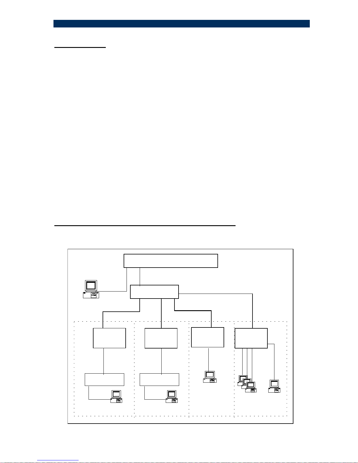
2 – Planning your network with S.CO1M/MA
This section will guide you through network planning in order to obtain maximum
benefits - in terms of performance and functionality - from the S.CON1M/MA System.
100Base-TX
Central Node Switch / Router
100Base-FX
FDX
100Base-FX
FDX F/O Links
100m
H.CON/MA
100Base-TX
10Base-T
100m
100m
100Base-TX 100Base-TX
100m
10Base-T
100Base-TX
S.CON1M/MA
10/100BaseTX
Switch 10/100BaseTX
Switch
10Base-T
S.CON1M LTA41/MAF.CON1/MA
SNMP
Manager 100Base-TX
Central Node Switch / Router
100Base-FX
FDX
100Base-FX
FDX F/O Links
100m
H.CON/MA
100Base-TX
10Base-T10Base-T
100m
100m
100Base-TX 100Base-TX
100m
10Base-T
100Base-TX
S.CON1M/MAS.CON1M/MA
10/100BaseTX
Switch
10/100BaseTX
Switch 10/100BaseTX
Switch
10/100BaseTX
Switch
10Base-T
S.CON1M LTA41/MAF.CON1/MA
SNMP
Manager
Typical basic configurations

S.CON1M/MA System
6
In the basic configuration drawing (previous page), any MA device can be connected
to the S.CON1M/MA (H.CON/MA, LTA41/MA, F.CON1/MA). A non-MA device
(S.CON1 or other) can be also connected (although in such case will not be
managed).
Any networking device may connect to the copper port of the S.CON1M/MA
converters: switches/routers (of any type).
While copper segment distance (between the device and the S.CON1M/MA) reaches a
maximum of 100m/330ft, the F/O segment (multi-mode fiber) may be extended to
2000m (6500ft) and much more over single-mode fiber. (Up to 150Km). Single Fiber
Strand (up to 40 Km) can be deployed saving 50 % of the cabling plant.
The S.CON1M/MA supports the Far End Fault (FEF) feature.
Far End Fault occurs when the signal detection is logically false from the receive
(incoming path) fiber port. When the S.CON1M/MA detects a F/O Link Loss condition,
the unit will automatically send a Far End Fault signal to the remote device. (on it
outgoing path). The remote device should support the same FEF feature and it will
indicate a Link Loss as well. (Refer to chapter 8 for more details).
The S.CON1M/MA supports the Fault Propagation mechanism (FO > TP, or/and TP
> FO), selectable through DIP switches (front panel) or via the management system.
When activated (FO > TP) if the S.CON1M/MA senses a loss of F/O Link, it will
automatically cut its TP port link. If TP > FO is enable, it will cut the F/O link in case
that the TP port link is disrupted. (See chapter 13 for a detailed explanation).
The S.CON1M/MA supports also the SLE feature.
FibroLAN’s Subscriber Link Emulation virtually emulates the subscriber’s device or
network connected to the TP port of the remote device (H.CON/MA) onto the TP link of
the Master Unit (S.CON1M/MA) connected usually to a switch/router (located in the
Access Node or Network Center).
When activated (controllable via the management system only) it senses the loss
of the TP link connected to the remote MA device, notifies the Master Unit and cuts off
the TP link connected to the switch/router, alerting in real time the switch/router of the
subscriber failure. All this is performed without disrupting the F/O link, thus ensuring
on-going control of the MA remote device via MA.
Two SLE modes of operation are available:
Downstream SLE mode of operation (link failure of the S.CON1M/MA TP port will
cause the disconnect of the TP port of the attached remote device.)
Upstream SLE mode (remote device link TP port failure will cause the disconnect of
the S.CON1M/MA TP port).
The aforementioned features make the S.CON1M/MA a reliable and outstanding
device for various and different environments.

S.CON1M/MA System
7
Private Industrial Managed Network
The SNMP Management module installed in the S.CON1M/MA System will monitor,
control and manage the remote MA devices. It will report alerts and traps to the SNMP
Manager located in the Headquarters building. On the other hand, the remote F.CON1
cannot be managed.
The SCON1M/MA equipped with a management module can be monitored and
managed from any SNMP management station running popular management
platforms (e.g. HP OpenView, SNMPc, etc)

S.CON1M/MA System
8
3. Contents of the shipping container
The contents of the S.CON1M/MA, shipping container are as follows:
• One S.CON1M/MA device.
• One AC power cord (excluding shipment to certain countries).
• Powered cords for DC (-48V) models are NOT supplied.
• RS232 management cable
• User and Installation Guide and/or Quick Guide
4 – Product General Description
The S.CON1M/MA family products are offered in several pre-configured models as
depicted in the table below.
Each of S.CON1M/MA units can be also equipped with an internal DC Power Supply
(PS48, -36 – 72 VDC), instead of the standard AC P.S.
ETR: Extended Temperature Range (-10°÷+70°C) option is applicable to all
S.CON1M/MA models.
SCON1M/MA products list table
S.CON1M/MA Single Channel 10/100Base-TX to 100Base-FX converter, BMD (Buffered Media
Domain), SC connectors, multi-mode - 2km,internal PS, SNMP Managed, MA
managed
S.CON1M/MA/T
Single Channel 10/100Base-TX to 100Base-FX converter, BMD (Buffered Media
Domain), ST connectors, multi-mode - 2km, internal PS, SNMP Managed, MA
managed
S.CON1M/MA/SMR7 Single Channel 10/100Base-TX to 100Base-FX converter, BMD (Buffered Media
Domain), SC connectors, single-mode - 7km, internal PS, SNMP Managed, MA
managed
S.CON1M/MA/SMR Single Channel 10/100Base-TX to 100Base-FX converter, BMD (Buffered Media
Domain), SC connectors, single-mode - 15km, internal PS, SNMP Managed, MA
managed
S.CON1M/MA/SM Single Channel 10/100Base-TX to 100Base-FX converter, BMD (Buffered Media
Domain), SC connectors, single-mode - 25km, internal PS, SNMP Managed, MA
managed
S.CON1M/MA/SM/L Single Channel 10/100Base-TX to 100Base-FX converter, BMD (Buffered Media
Domain), SC connectors, single-mode - 40km, internal PS, SNMP Managed, MA
managed
S.CON1M/MASM/L/2 Single Channel 10/100Base-TX to 100Base-FX converter, BMD (Buffered Media
Domain), SC connectors, single-mode - 70km, internal PS, SNMP Managed, MA
managed
S.CON1M/MA/SM/L/3 Single Channel 10/100Base-TX to 100Base-FX converter, BMD (Buffered Media
Domain), SC connectors, single-mode - 100km, 1550nm, internal PS, SNMP
Managed, MA managed
S.CON1M/MA/SM/L/X Single Channel 10/100Base-TX to 100Base-FX converter, BMD (Buffered Media
Domain), SC connectors, single-mode - 150km, 1550nm, internal PS, SNMP
Managed, MA managed
S.CON1M/MA/SMRF1 Single Channel 10/100Base-TX to 100Base-FX converter, BMD (Buffered Media
Domain), single SC connector, single-mode - 20km, Single Fiber Strand, 1310nm
TX/ Rx, internal PS, SNMP Managed, MA managed
S.CON1M/MA/SMRF13
Single Channel 10/100Base-TX to 100Base-FX converter, BMD (Buffered Media
Domain), single SC connector, single-mode - 15km, Single Fiber Strand, 1310nm
Tx/1550nm Rx internal PS, SNMP Managed, MA managed
S.CON1M/MA/SMRF15
Single Channel 10/100Base-TX to 100Base-FX converter, BMD
(Buffered Media Domain), single SC connector, single-mode - 15km, Single Fiber
Strand, 1550nm Rx /1310nm Rx internal PS, SNMP Managed, MA managed

S.CON1M/MA System
9
Key Features
• 10Base-T, 100Base-TX and 100Base-FX modes of operation
• Supports FEF feature (Far-End-Fault)
• Supports bi-directional Fault Propagation (FO>TP and/ or TP>FO)
• Supports SLE (Subscriber Link Emulation)
• Comprehensive LED support :Indicators for Link, Activity (Tx, Rx), MA
active, FDX, 100M, SD (signal detect) and power status
• Hardware based 10/100, Full/Half, Flow control and Auto-Negotiation
• Wire speed reception and transmission
• Supports 1K Mac addresses
• Frame length range: 64 ÷ 1536 bytes (VLAN tagged frames are thus
supported and can pass thru the converter)
• Desktop, shelf or wall mount installation
• ETR: Extended Temperature Range (-10°÷70°C) option for all
S.CON1M/MA models
• Optional -48Vdc Power Supply for all S.CON1M/MA models (PS48)
• RS232 Console port for Out-band management on the front panel
• SNMP management and MA support.
• Telnet support from an SNMP management station or from the
Terminal connected to the RS232 port
• Loop-back on Fiber Optic Link (via management only)
General Description
All S.CON1M/MA models have identical functionality and performance. Therefore, any
description or feature of one model refers to all other types.
The RJ-45 port operates in Auto-Negotiation mode: It may operate in 100Base-TX or
10Base-T and in both FDX and HDX modes, depending on the type of device to which
it is connected.
The TP port is a shielded RJ-45 port, cat.5, and 100m. The port can operate as an
MDI-II or MDI-X port depending on the MDI-II /MDI-X selector.
The S.CON1M/MA is equipped with an MDI-II/MDI-X selector on the front panel to
allow connection of either a switch/hub or a station, allowing the deployment of either a
straight or cross-twisted pair cable.
The F/O port supports 100Base-FX transmission in both FDX and HDX modes.
The conversion process creates a BMD, allowing unprecedented functionality and
performance. The F/O port is setup by default to operate at 100Mbps FDX
For optimized set-up, the S.CON1M/MA is equipped with an array of 7 DIP switches
accessible from the front panel.

S.CON1M/MA System
10
The device provides extensive diagnostics and a status display with 7 high visibility
LEDs.
Power Supply (including –48 models):
The system is equipped with an internal overrated power supply (100 - 240V universal
input or –48VDC. A front panel LED indicates the power status.
Management:
The S.CON1M/MA includes on its front panel in addition to the above-mentioned
indicators and controls a “management area”. This area includes all necessary
interfaces to run the CLI management (RS232 Console port and two LEDs RCV and
Ready.
S.CON1M/MA Management: the unit can be monitored / controlled in three ways:
a. Managing with SNMP ( Network connection: In-band management):
You can monitor/control the S.CON1M/MA media converter and the remote MA device
using SNMP management station. Ensure that the DIP switch S7 is in UP position (Disable
VLAN). If the SNMP station is connected directly to S.CON1M/MA TP port, set S7 to Down
(VLAN enable) position.
b. Telnet from SNMP management station: (statuses monitoring and MA commands)
c. CLI management with a terminal (RS232 port): (statuses monitoring and MA
commands)
You will need a terminal emulation program (such as “ Hyper Terminal)
Telnet is also supported through the RS232 port
Notes: You may download software upgrade for the S.CON1M/MA with the TFTP
routine For a detailed description, please refer to section 16 (“Configuring, and
managing S.CON1M/MA”)
S.CON1M/MA System
11
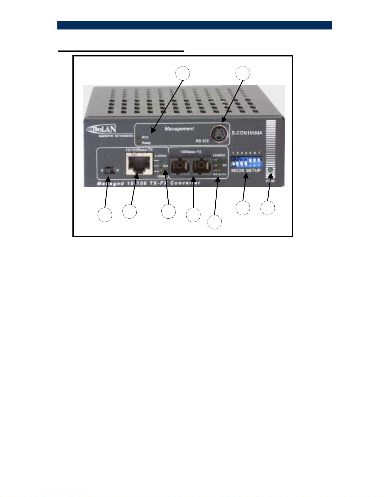
5 – Front Panel components
1- MDI-II / MDI-X selector
2- 10/100Base-TX connector port (shielded RJ45)
3- Twisted pair operation (3 LEDs, 4 functions)
Link/ Act - twisted pair link present (LED steady lit)
When blinking implies activity (transmit or receive mode)
FDX - full duplex operation
100M - TP is working at 100Mbps (when the LED is off, the speed is 10Mbps)
4- SC fiber optic connector (left/TX & right/Rx); ST connector (S.CON1M/MA/T model)
5- Fiber optic LED indicators
Link/ Act -
a. steady lit (green) F/O Link OK, MA not Active
b. blinking: data received/transmitted. When MA is Active then this LED will
be blinking even if no user data is received/transmitted
SD (signal detect) optical signal present
MA active: steady lit (amber): the S.CON1M/MA is connected to a remote MA
enabled and active device.
6- MODE SETUP 7 positions DIP switch
7- POWER LED indicator
LED lit Main power supply installed and operating.
8- MiniDIN connector for management set-up (RS232 Console port)
9- Management module status LED indicators
RCV – the internal SNMP agent is receiving data
Ready–LED is blinking implies that the SNMP agent logic is in the initialization
stage. When LED steady lit: SNMP agent is ready
12 3 45
6 7
89

S.CON1M/MA System
12
6 – Installation
S.CON1M/MA all models (including –48 VDC models).
The device is intended for use with indoors power lines only
The S.CON1M/MA product is suitable for desktop, shelf or wall mount installation
For Desktop use: Affix the supplied plastic “feet” (after peeling off the adhesive
protecting sheet) to the bottom of the devices, with each “foot” approximately 1 cm
from each edge. Place the device horizontally on a hard, clean surface (desk, shelf,
etc.), leaving free space around it for natural ventilation. Avoid placing the device on
other active, heat generating equipment and avoid placing such devices on other
S.CON1M/MA unit.
For wall mount installation
Attach the single channel wall mount kit (SCH – WM part # B161) with two (supplied)
screws to the base of the S.CON1M/MA unit (select any 2 adjacent nuts: 1+2 or 3+4
or1+3 or 2+4) to achieve the desired mode of mounting. The screws to be fixed on the
wall should not protrude more than 8mm. Append the S.CON1M/MA unit on the wall.
For Shelf installation:
Use the 19” Rack shelf (CTF-RM P/N B012) for installation of up to 3 S.CON1M/MA
units.
During the installation of several 19” Rack shelves, it is recommended to leave at least
1cm ventilation space between two adjacent racks.

S.CON1M/MA System
13
7 – Power Connection
CAUTION: When connecting a device to an AC (DC) power outlet,
always first connect the cord to the device, and ensure that it is
securely fastened. Only afterward connect the cord to the wall
outlet. Make sure to use grounded (3 way) outlets (in case of AC
models).
NEVER OPEN THE DEVICE WHEN IT IS CONNECTED TO POWER LINES!
For each country FibroLAN (or FibroLAN’s distributor) provide with the product an
appropriate power supply cord which is safety approved in accordance with related
country’s National Electric Code
Connect to AC line socket at the rear of the converter, using the included power cord. The
S.CON1M/MA will accept and automatically switch between any line voltage from 100 to 240
VAC, 50-60 Hz. There is no ON/OFF switch on the device. When the power is connected to
the device, the device is ON. This will be indicated by the POWER LED on the front panel
being illuminated.
S.CON1M/MA all AC models Rear Panel
S.CON1M/MA with 48 VDC Power Supply ( PS48 -36 ÷- 72 VDC )
Proceed as above using a suitable DC supply cable. Ensure that the polarity of the cable
complies with the polarity of the DC receptacle on the device as depicted above. There is no
ON/OFF switch on the device. When the power is connected to the device, the unit is ON.
This will be indicated by the POWER LED being illuminated.
0V -48VDC
S.CON1M/MA System
14
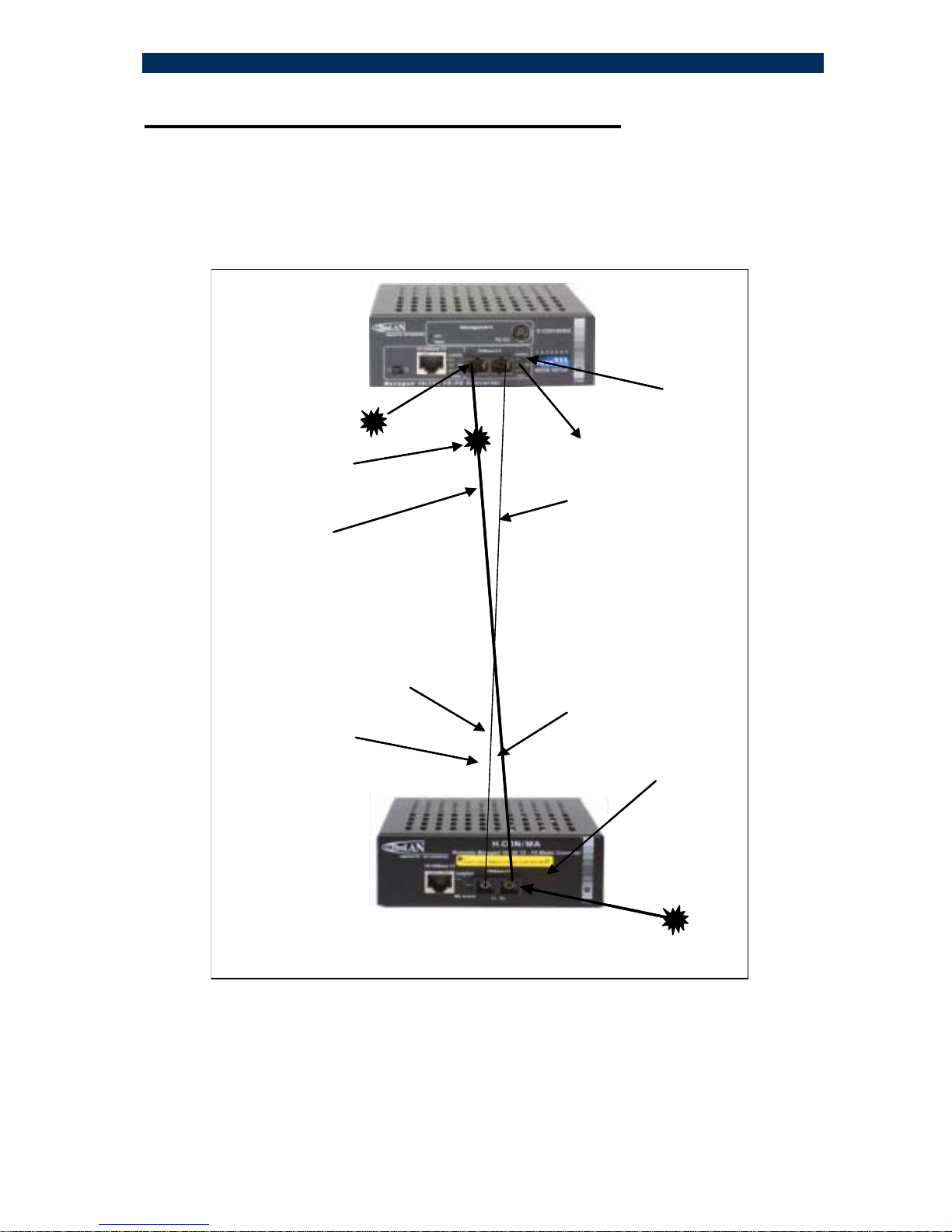
8 – 100Base-FX Far End Fault (FEF feature)
Far End Fault occurs when the signal detection is logically false on the receive
(incoming path) fiber port. When the remote device H.CON/MA detects a F/O Link
failure condition, the unit will automatically send a Far End Fault signal to the
S.CON1M/MA device (on its outgoing path). The S.CON1M/MA does support the
same FEF feature and it will indicate a F/O Link Loss as well. The picture below
depicts the FEF functionality.
Fiber 2
TX
ConverterA
ConverterA will show
F/O LINK DOWN
ConverterB
Receive path
Transmit path
FEF signal
Fiber 1
RX
Fiber 2 failure
Converter B will show F/O Link DOWN
SD (SignalDetectLED willlit
Ifany element of Receive path has failed,Converter B willsend a
FEF signalto Converter A which will show its F/O Link OFF
S.CON1M/MA
H.CON/MA
By means of the FEF feature along with the SD ( Signal Detect ) LED , we may
determine which fiber line connection is faulty within the F/O Link ( if one of the two
F/O lines is disrupted ). The SD LED lit in converter A implies that its F/O Tx line is
faulty. The combination of the FEF feature and the SD LED ( Signal Detect :
implies data signal present during Receive Mode ) provides a powerful and
efficient troubleshooting tool to easily identify a failed fiber connection within a
F/O link.

S.CON1M/MA System
15
9 - Fiber Optic Connection
The S.CON1M/MA is equipped with 1 pair of SC-type connector or single SC
connector for SFS (Single –Fiber – Strand) models.
Do not remove the protective covers on the fiber connectors until you are ready to
connect the fiber optic cables. Power should be connected before attaching the fiber
optic cables. When dealing with fiber optic cables, it is essential to ensure that the Tx
at one end of the link is connected to the Rx at the other end of the link.
Some duplex fiber optic cables are color coded to help monitor the direction of data
transmission. If the fibers are not coded, special attention must be paid to ensure a
proper connection.
F/O port specifications
Model F/O
Port Transmit
WL Minimal
Output
Power
Receive
WL Typical
Receive
Sensitivity
Suggested
Distance
Km
S.CON1M/MA Duplex SC,
m/m 1310nm - 18dBm 1310nm -32dBm 0-2
S.CON1M/MA/SMR7 Duplex SC,
s/m 1310nm -20dBm 1310nm -30dBm 0-7
S.CON1M/MA/SMR Duplex SC,
s/m 1310nm -15dBm 1310nm -30dBm 015
S.CON1M/MA/SM Duplex SC,
s/m 1310nm -15dBm 1310nm -33dBm 0-25
S.CON1M/MA/SML Duplex SC,
s/m 1310nm -11dBm 1310nm -33dBm 15-40
S.CON1M/MA/SML2 Duplex SC,
s/m 1310nm -2dBm 1310nm -35dBm 25-70
S.CON1M/MA/SML3 Duplex SC,
s/m 1550nm -5dBm 1550nm -38dBm 40-100
S.CON1M/MA/SMLX Duplex SC,
s/m 1550nm 0dBm 1550nm -38dBm 70-150
S.CON1M/MASMRF1 Simplex SC,
s/m 13100nm -15dBm 1310nm -30dBm 0-15
S.CON1M/MASMRF13 Simplex SC,
s/m 1310nm -15dBm 1550nm -30dBm 0-15
S.CON1M/MASMRF15 Simplex SC,
s/m 1550nm -15dBm 1310nm -30dBm 0-15

S.CON1M/MA System
16
CAUTION
Radiation emitted from a fiber optic
connector may be hazardous to human
vision. Therefore, the following rules
must be strictly observed
All single-mode (SM) models are
CLASS I LASER PRODUCTS
And must be handled with special care
.
When not in use, keep the fiber optic
connector closed using its protective
cover.
Never stare directly into the fiber optic
connector of a powered device or into
the end of a fiber connected to it.
10 - Twisted Pair Cable Connection
The S.CON1M/MA provides one shielded RJ-45 connector to interface to the twisted
pair link. The port operates in Auto –negotiation mode and according to the position of
the MDI-II / MDI-X selector switch located on the front panel
Use a shielded Cable Type 5 or higher grade, up to 100m (330ft) long.
STP cable carries a higher quality of signal and is less sensitive to environmental
noise. The 10/100BaseTX port is normally designed to be connected directly to a
workstation, using a standard straight through patch cable.
In order to connect a Hub, or a switch, a crossover cable is normally used
The tables below depict these functionalities.
Rules: With the same type of TP ports (MDI-X < > MDI-X, or MDI > < MDI)
Use a crossover cable. With different ports (MDI-X < > MDI) use a straight cable.
Set up the selector (MDI-II/MDX) located on the front panel according to the available TP
type cable and the setup of the remote connected TP port. Check if the remote TP port
does support Auto-Negotiation and act accordingly.
S.CON1M/MA System
17
11 – DIP Switches Setting
Each S.CON1M/MA unit is equipped with an array of DIP switches that facilitate the
proper setting of the TP and F/O ports for optimal operation.
Each port may have different settings.
A wrong setting will not necessarily result in a channel malfunction, but rather in non-
optimal operation (for instance - HDX operation instead of FDX).
The switches are recessed in the front panel to avoid incidental change of position.
Use a flat-head miniature screwdriver (or a similar tool), insert it through the slot, hold it
vertically to the panel against the switch to be set, and change its position up or down
according to the following table.
The below table shows that the S.CON1M/MA is configured in Auto-Negotiation mode.
The VLAN mode (when enabled via S7) implies that the internal management port
and the TP port form one VLAN. For local SNMP management (SNMP Manager
connected to local TP port) set switch the S7 to down position (VLAN enabled)
For remote SNMP management (SNMP manager station connected to remote
network), ensure that S7 is in UP position (VLAN disable)
S1 S2 S3 S4 S5 S6 S7
Down – LinkTest( FPdisable)
Up – F > T ( FP enable )
Down - DON’T CARE
Up - DON’TCARE
Down - 10/100BaseTXFDX
Up - 10/100BaseTXHDX
Down -DON’TCARE
Up - DON’T CARE
Down - 100BaseTX
Up - 10BaseT
When Auto-Neg
Is Enabled
Down - Auto-Negotiation Enable
Up - Auto-Negotiation Disable
NotUsed
When Auto-Neg
Is Disabled
When Auto-Neg
Is Disabled Note :
After each configuration setting,
move S6 to down position and
move it up back after onesecond
Up – T > F ( FP enable )
Down– LinkTest(FPdisable)
Up - NORMAL
Down - RESET
Up - VLAN Disable
Down – VLAN Enable
S1 S2 S3 S4 S5 S6 S7S1 S2 S3 S4 S5 S6 S7
Down – LinkTest(FPdisable)
Up – F > T ( FP enable )
Down - DON’T CARE
Up - DON’TCARE
Down - 10/100BaseTXFDX
Up - 10/100BaseTXHDX
Down -DON’TCARE
Up - DON’T CARE
Down - 100BaseTX
Up - 10BaseT
When Auto-Neg
Is Enabled
Down - Auto-Negotiation Enable
Up - Auto-Negotiation Disable
NotUsed
When Auto-Neg
Is Disabled
When Auto-Neg
Is Disabled Note :
After each configuration setting,
move S6 to down position and
move it up back after onesecond
Up – T > F ( FP enable )
Down– LinkTest(FPdisable)
Up - NORMAL
Down - RESET
Up - VLAN Disable
Down – VLAN Enable

S.CON1M/MA System
18
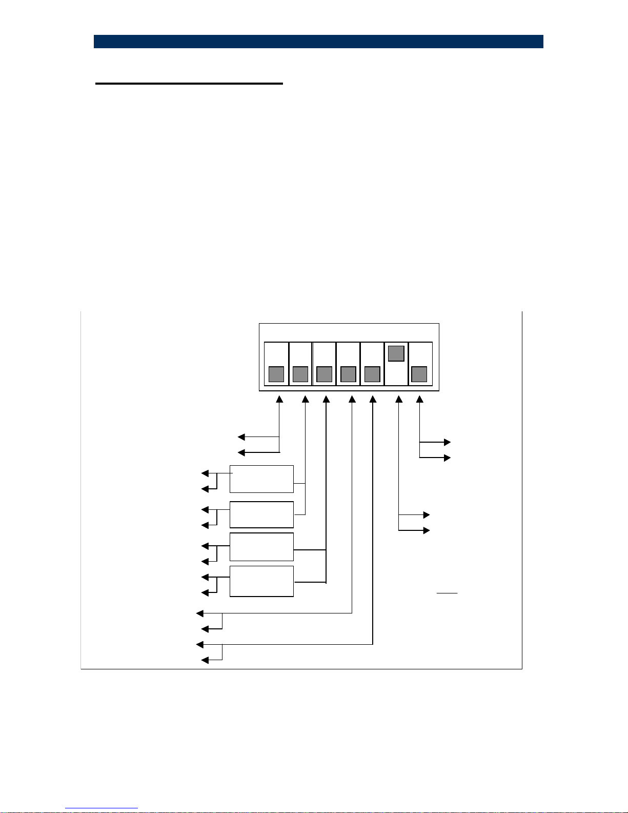
12- MA™ Concept and Functions
The MA™ (Micro Agent) is an on-chip management system providing the monitoring
and management of remote access devices without the need of an expensive SNMP
agent module. The MA™ does not require an IP address.
The chip is embedded in both the remote unit, mostly referred to as a CPE, and in the
Master Unit (normally installed in the Node Unit). A unique secured in-band
management protocol allows the two devices communicating between themselves
over the fiber link bi-directionally, therefore both monitoring and management
commands can be remotely performed on the CPE. Control frames are not
forwarded to data ports.
Micro Agent Basic System Block Diagram
Master Unit (S.CON1M/MA) Remote Device (CPE Unit)
When MA™ enabled devices are deployed at both ends of the fiber link, they
automatically learn about each other’s presence and begin providing full remote
management functions within 20 to 30m.seconds from the moment the link has been
established. However, if an MA™ enabled devices cannot complete such handshake
within that time, it concludes that the opposite end device is not MA™ enabled,
subsequently it bypasses its special functions and operates like a standard, straight
forward access device. Therefore there are no interoperability issues between network
devices which have MA™ chips embedded in them and those that have not.
The following management functions are available for the H.CON/MA unit attached to the
S.CON1M/MA device:
• F/O Link Status and changes
• T/P link Status and changes
• Fiber Link Integrity: continuous (every 10ms) verification of the fiber link
• Loop –Back test and Extended Loop Back (ELB)
• Power On: CPE Power On; equivalent to CPE ‘s log-into the network
• Set A/N mode: CPE’s TP port may be set to Auto-Negotiation or non A/N mode
• Set speed Mode: select 10 or 100Mbps on the TP port
• Set Duplex Mode: allows forcing of HDX or FDX onto the TP port
• Death Gasp: alerting the center of a power failure
• Rate Limiting: allows supplying user with different service programs, from
256Kb to 100Mbps (up and down streams)
• Fault Propagation (F >> T) enable / disable
• SLE (Subscriber Link Emulation) enable /disable
• Reset the device and/or Restore the device’s default configuration
Optical Link
TP
PH Micro
Agent
Micro
Agent
SNMP
Agent
TP Fiber
Phy
Fiber
Phy
TP
Phy
TP
Network Interface
Data
Status & Control

S.CON1M/MA System
19
13 - Fault Propagation and SLE mechanisms
The main purpose of fault propagation mechanisms implemented in media converters
is to allow real-time notification of any link failure to upper hierarchy devices (e.g.
switches/routers with redundant links) consequently activating an alternate path to
communicate with a mission critical site. However, such mechanisms implemented in
other vendors’ products, may suffer from an inherent drawback. These are typical bi-
directional mechanisms: fault propagates both from fiber to TP port and from TP to the
fiber port. If such devices are modern and implement FEF as well, then it may become
a lethal combination: while propagating the fault as intended, when fault (original link
break) is repaired (i.e. original link is restored), such systems will hang and will be
restored only by manual intervention.
The powerful fault-propagation mechanism implemented in the S.CON1M/MA prevents
such a deadlock. The fault propagation is bi-directional, (F >T, and/or T > F)
In order to optimize the network, you must first decide what is the critical site needing
redundancy, consequently establish the general direction of fault propagation required,
finally set up accordingly.
The mostly common use is (at the central node) F>>T: propagation: failure of the fiber
link will cut the TP link connected to the router/switch, which in turn will activate an
alternate path to the remote site. (In our case the remote device attached to the
S.CON1M/MA)
While the FP mechanism is “fool-proof”, the safe implementation of FP system-wise
depends now on remote device (the remote device connected to the opposite end of
the F/O link). If such device does not have a FP feature (or it is disabled) then no
problem – the network will behave according to the setting of the S.CON1M/MA
(F>>T enabled) without of risk of hanging. If the remote device is equipped with a FP
mechanism make sure that it is NOT bi-directional, otherwise you risk hanging as
explained above. In such case, it is recommended to configure the remote device to
one FP mode (F > T)
If the remote device is equipped with selective or just one-way FP then there should be
no risk in implementation. However, as such mechanisms are proprietary by nature,
we cannot guarantee end-to-end smooth operation.
If the remote device is another FibroLAN’s MA™ (like the H.CON/MA) and the Master
Unit (S.CON1M/MA, FibroLAN Metrostar™, F.CON8/16/MA, F.CON12/MA/TL) is
managed, the most powerful SLE feature comes into the picture, further enhancing
your network’s resilience.
FibroLAN’s Subscriber Link Emulation virtually emulates the subscriber’s device or
network connected to the TP port of the remote device (converter) onto the TP link
of the Master Unit (connected usually to a switch/router). When activated
(controllable via the management system only) it senses the loss of the TP link
connected to the remote MA device, and will cause the Master Unit to cut off its related
TP link (connected to a switch/router), alerting in real time the switch/router of the
subscriber failure. All this is performed without disrupting the F/O link, thus
ensuring on-going control of the remote MA device via MA management.

S.CON1M/MA System
20
It should be noted that if the TP port of the Master Unit (normally connected to
the switch / router ) has failed, the SLE will cut-off the remote MA device’s TP
port, providing in this manner an optimal bi-directional safe operation.
Thus Two SLE modes of operation are available :
Downstream SLE mode of operation (link failure of the S.CON1M/MA TP port will
cause the disconnect of the TP port of the remote MA device.)
Upstream SLE mode (remote MA device link TP port failure will cause the disconnect
of the S.CON1M/MA TP port).
The SLE may be used independently or in conjunction with the previously described
FP mechanism enabled in the Master Unit and in the remote MA device. When both
mechanisms are activated (F>T and SLE) then the TP link connecting the appropriate
port (in the Master Unit) to the switch/router will be cut off upon the occurrence of any
one (or more) of the following events:
! F/O cable broken
! F/O transmission from the Master Unit failed
! F/O receiver of the Master Unit failed
! General Failure of the remote device
! Reception failure of the remote device
! Transmission failure of the remote device
! Outgoing path fiber from Master Unit disrupted.
! Subscriber failed or disconnected (remote device’s TP port failure)
Again it must be emphasized that this extensive set of features is obtained only if MA
enabled devices are installed at both ends of the link.
The LINK TEST mode: it is possible to enable the Link Test in the S.CON1M/MA unit
Through DIP switches S4 and S5 (see chapter 11) or through management
commands disabling the FP mechanisms. Set (or remain) in this mode in 2 cases:
! Whenever your network cannot benefit from FP (i.e. alternate route is not
available)
! For diagnostic purposes: in this mode each of the link segments (typically 3: TP,
F/O, TP) provides separate and true indication of its integrity therefore the
defective segment can be identified and consequently repaired.
____________________________NOTES________________________________
While in TEST mode, the S.CON1M/MA provides full functionality and run normal
traffic, except the fault propagation. In other words, if one or both converters forming
the link are – by mistake or negligence left in this mode, it will not obstruct normal
traffic.
Table of contents
Other FibroLAN Media Converter manuals


