FibroLAN MSM100U Manual

MSM100U/ Module
Universal Multi/Single-Mode
To Single-Mode Media Converter
User and Installation Guide
Version: 2.0
FibroLAN Ltd.
6 Hayezira St. P.O. Box 544 Yokneam-Illit, 20692 ISRAEL
Tel: 972-4-9591717 Fax: 972-4-9591718

MSM100U Module Converter/Extender
2
Table of contents
Overview page 4
Main Features page 4
Planning your network with MSM100U page 4
Module models page 5
MetroStar chassis layout page 6
Module front panel page 7
Installation procedure page 8
F/O cabling connection page 9
F/O ports specifications page 10
DIP slide switches setting page 11
MSM100U management page 11
Typical Network page 12
Troubleshooting page 13
Specifications page 14
Warranty Limitation page 15
Thank you for purchasing this
MSM100Uquality module converter from
FibroLAN. We hope that this guide will help
you to obtain the best results from the device
while minimizing installation time.
If you still need help installing or troubleshooting the MSM100U/622U converter after
reading the detailed information in this guide, please visit our web site
(www.fibrolan.com), contact your reseller, or call FibroLAN directly.
Note: Unless indicated otherwise, in this guide MSM100U applies to MSM100U-
SMR7, MSM100U-SMR, MSM100U-SM, MSM100U-SML, MSM100U-SML2, MSM100U-
SML3, MSM100U-SMLX, MSM100U-SMRF13, MSM100U-SMRF15,
MSM100U-SME, MSM100U-SME-7-7, MSM100U-SME-L1-1, and MSM100U-SME-L3-3.
TRADEMARKS
Any trademarks mentioned in this manual are acknowledged to be the property of the trademark
owners.

MSM100U Module Converter/Extender
3
FEDERAL COMMUNICATIONS COMMISSION
AND
CANADIAN DEPARTMENT OF COMMUNICATIONS
RADIO FREQUENCY INTERFERENCE STATEMENTS
This equipment generates, uses, and can radiate radio frequency energy and if
not installed and used properly, that is, in strict accordance with the
manufacturer’s instructions, may cause interference to radio communication.
It has been tested and found to comply with the limits for a Class A computing
device in accordance with the specifications in Subpart B of Part 15 of FCC
rules, which are designed to provide reasonable protection against such
interference when the equipment is operated in a commercial environment.
Operation of this equipment in a residential area is likely to cause interference,
in which case the user at his own expense will be required to take whatever
measures may be necessary to correct the interference.
Changes or modifications not expressly approved by the party responsible for
compliance could void the user’s authority to operate the equipment.
This digital apparatus does not exceed the Class A limits for radio noise
emission from digital apparatus set out in the Radio Interference Regulation of
the Canadian Department of Communications.
Le présent appareil numérique n’émet pas de bruits radioélectriques dépassant les limites
applicables aux appareils numériques de la classe A prescrites dans le Règlement sur le
brouillage radioélectrique publié par le ministère des Communications du Canada.
CE Mark
The CE mark symbolizes compliance with the European Community
required technical standards.
The product herewith complies with the requirements of the EMC
Directive 89/336/EEC,the Low Voltage Directive 73/23/EEC and the
R&TTE Directive 99/5/EC.
The product was tested in a typical configuration.
Levy Malkiely
Quality Manager

MSM100U Module Converter/Extender
4
1 - Overview
A media-converter may be defined as a device connecting two active network
components point-to-point over a media that is different from the ports of at least one
of these devices.
An ideal media-converter should be a transparent element in the network, and its
ports may be considered as integral parts of the devices interconnected by it.
Most of the high speed networking devices (such as ATM or Fast-Ethernet switches)
are available with multi-mode fiber-optic ports. Other devices – when offered with
Single-Mode fiber interfaces are very expensive and not flexible in use.
The MSM100U module series for the MetroStar System provides the network
designer with a flexible, cost effective device for network extension.
The MSM100U is a universal, protocol transparent device; converting optical signals
ranging up to 155Mbps from multi-mode to single mode fibers and distances of up to
150km (data rate covers range from 40 to 155Mbps)
Being transparent, their deployment is easy and does not require any settings or
measurements.
The device is protocol independent for the specified transmission speed however it is
delivered qualified for the 2 most popular standards in this range: ATM/OC3 and
100Base-FX.
MSM100U models may be used with Single Fiber F/O ports for network extension
or wavelength converters.
2 - Key Features
•Easy Installation – protocol independent, plug-and-play
•Network extension – up to 150km
•Data Rate – up to 155Mbps (100FX/ATM/OC3)
Loop-back feature for each F/O port
•DIP slide switches set-up
3 - Planning your network with MSM100U module
When planning an optical network based on the MSM100U you have to take care of
only one issue: the proper duplex mode of the entire network. As a rule, the entire
network should be set to the same mode: FDX: in this case both throughputs and
distances are maximized.
The MSM100U module family series are normally deployed in ATM/OC3 environment
or in Fast Ethernet networks covering distances up to 150 Km.

MSM100U Module Converter/Extender
5
4 - Module models
The MSM100U/622U modules are offered in the pre-configured versions as described in the
table below:
MSM100U-SMR7 Universal (100FX/ATM/OC3) Conversion Module, Multi Mode to Single
Mode 1310nm, 7km 2*dual SC
MSM100U-SMR Universal (100FX/ATM/OC3) Conversion Module, Multi Mode to Single
Mode 1310nm, 15km 2*dual SC
MSM100U-SM Universal (100FX/ATM/OC3) Conversion Module, Multi Mode to Single
Mode 1310nm, 25km 2*dual SC
MSM100U-SML Universal (100FX/ATM/OC3) Conversion Module, Multi Mode to Single
Mode 1310nm, 40km 2*dual SC
MSM100U-SML2 Universal (100FX/ATM/OC3) Conversion Module, Multi Mode to Single
Mode 1310nm, 70km '2*dual SC
MSM100U-SML3 Universal (100FX/ATM/OC3) Conversion Module, Multi Mode to Single
Mode 1550nm100km, 2*dual SC
MSM100U-SMLX Universal (100FX/ATM/OC3) Conversion Module, Multi Mode to Single
Mode 1310nm, 150km, 2*dual SC
MSM100U-SMRF13 Universal (100FX/ATM/OC3) Conversion Module, Multi Mode to Single
Mode Single Fiber Strand 1310nm Tx, 15km, 1 single+ 1 dual SC
MSM100U-SMRF15 Universal (100FX/ATM/OC3) Conversion Module, MMF to SMF Single Fiber
Strand 1550nm Tx, 15km, 1 single+ 1dual SC
MSM100U-SME Universal (100FX/ATM/OC3) Module, SMF to SMF Extender 1310nm, 7km
to 25km, 2*dual SC
MSM100U-SME-7-7 Universal (100FX/ATM/OC3) Module, SMF to SMF Extender 1310nm, 7km
to 7km, 2*dual SC
MSM100U-SME-L1-1 Universal (100FX/ATM/OC3) Module, SMF to SMF Extender 1310nm, 40km
to 40km, 2*dual SC
MSM100U-SME-L3-3 Universal (100FX/ATM/OC3) Module, SMF to SMF Extender 1550nm DFB,
100km to 100km, 2*dual SC
MMF = Multi-Mode Fiber
SMF = Single- Mode Fiber
Products may be ordered with both F/O ports Single-Mode fiber to be deployed as network
extenders or wavelength converters.
Signals received on the F/O Multi-mode port (Duplex SC connector) are converted to
Single Mode optical signals transmitted from the Single Mode F/O port (Duplex SC
connector).
The F/O port supports 100Base FX transmission in FDX mode in Fast Ethernet or
ATM/OC3 155Mpbs protocol.
MSM100U Module Converter/Extender
6
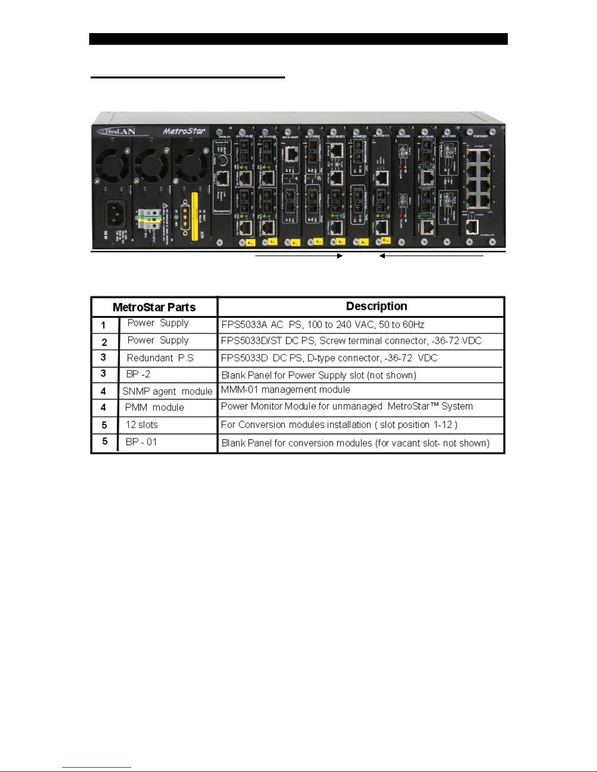
5 - MetroStar chassis layout
1 2 3 4 1 5 12
In slot position # 3 (from the left), it is possible to install an additional redundant
Power Supply or the Blank panel BP-02.
Slot position # 4 is normally dedicated for the
Metro Star™
SNMP management
module, MMM-01 for standalone
Metro Star™
.
The optional PMM module is normally installed in slot # 4 in unmanaged
MetroStar™
System.
When the
MetroStar™
chassis is not fully populated with conversion modules, it is
mandatory to install the BP-01 Blank Panel in the vacant slots.

MSM100U Module Converter/Extender
7
6 - Module front panel components
Port 1
•Multi-Mode (or Single Mode) Duplex SC connector (Tx and Rx)
•SD (Signal Detect) green LED – when lit indicates presence of Signal received
on Rx side of the MM/SM DSC connector.
•Loop-back red LED indicator: lit indicates port is in loop-back mode
Data from transmitter port is routed back to its receiver port
Port 2
•Single Mode Duplex SC connector (Tx and Rx)
•SD (Signal Detect) green LED: when lit indicates presence of Signal received
on Rx side of the SM DSC connector.
•Loop-back red LED indicator: lit indicates port is in loop-back mode
Data from transmitter port is routed back to its receiver port
Note: You may perform a Loop-Back operation on Port 1 or Port 2
Loop-Back on both ports simultaneously is not allowed
Power (ON) green LED (PWR) indicates module is receiving power

MSM100U Module Converter/Extender
8
7 - Installation
Slot assignment
MSM100U module may be installed in any of the slots marked 1 to 12,
However by installing modules systematically next to each other (from left to right) it will
make it easier to install additional modules in the future allowing clear access to the slots.
Installation of Modules
All MetroStar™ modules are hot swappable however it is recommended – whenever
operationally acceptable, to install a module (or swap an already installed module) while
the system is powered OFF.
All modules are equipped with two self-clinching screws – always use BOTH of them for
safe insertion and removal of modules into/from the system.
To install a module in a vacant slot:remove the blank panel covering the slot using a
crosshead screwdriver. Hold the module vertically with one hand by the side facets of the
metal frame of the module. Do not touch the PCB (printed circuit board) or any of the
components with your hand. The frame is asymmetrical: its bottom end rectangular while
its other side has a diagonally “cut” edge – make sure this side is up. Align both upper and
lower edges of the PCB with the lower and upper Nylon guides of the slot and gently glide
the module into the slot, applying only a small pressure. If correctly positioned and
aligned, it should allow the module all the way in. At the final stage (2-3 mm short of full
insertion) you will experience a slightly higher resistance – apply a higher pressure with
your finger on the panel of the module till you feel it “clicks in” and its panel is flush with
the surface of the chassis. At this point, if the MetroStar™ is powered ON the PWR
LED (left-upper side of the module or any corresponding LEDs on the PMM) will light. If
not lit, ensure that unit is powered UP; if still not lit – remove the module and re-insert. Is
problem persists; troubleshoot by inserting same module in a different slot and/or another
module in the suspected slot. Fasten both self-clinching screws using your fingers by
turning them clockwise, while doing that an increasing resistance indicates that the screw
is well aligned with its nut. Finally, using a crosshead screwdriver fasten both screws
(normally no more than one full turn will be required). Make sure not to apply excess
power.
To Swap a module:Unfasten the 2 screws using a cross-head screwdriver then continue
by turning them with your fingers counter-clockwise till the head of the screw “pops out”.
Hold both screws with fingers of BOTH hands and pull the module out. Ensure applying
balanced force at both screws to maintain vertical position throughout the process,
although it might be necessary to slightly tilt the module at the very first mm. Continue as
above to insert the new module. If you choose to leave the slot vacant, always close it with
a blank panel.
Warning: Do not INSTALL a module into a slot with already attached F/O
cabling. Connect the F/O cables to the module ports only after having verified
that the module is well inserted and its Power LED is lit.
Conversely, DISCONNECT the F/O cabling from the module ports before
replacing it. Non-compliance with the above procedures may cause module’s
malfunction.
MSM100U Module Converter/Extender
9
8 - Fiber Optic Connection
The MSM100U module is equipped with a pairs of Duplex SC-type connectors.
Do not remove the protective covers on the fiber connectors until you are ready to
connect the fiber optic cables. Power should be connected before attaching the fiber
optic cables. When dealing with fiber optic cables, it is essential to ensure that the TX
at one end of the link is connected to the RX at the other end of the link. Some
duplex fiber optic cables are color coded to help monitor the direction of data
transmission. If the fibers are not coded, special attention must be paid to ensure a
proper connection. Remember that at both local and remote sites the transmit and
receive fibers must be connected
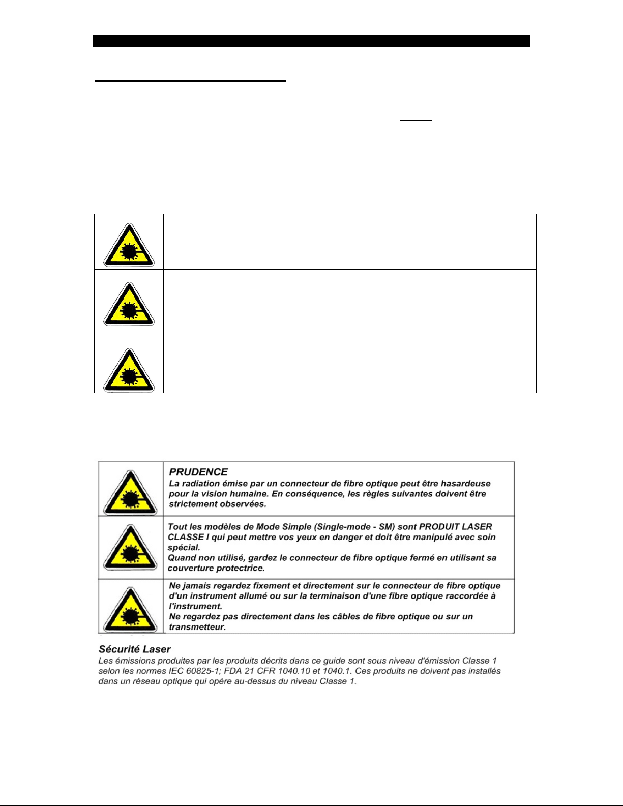
CAUTION
Radiation emitted from a fiber optic connector may be hazardous
to human vision. Therefore, the following rules must be strictly
observed
All Single-mode (SM) models are CLASS I LASER PRODUCT that
may endanger your eyes and must be handled with special care
When not in use, keep the fiber optic connector closed using its
protective cover
Never stare directly into the fiber optic connector of a powered
device or into the end of a fiber connected to it.
Do not look directly into the fiber optic cables or transmitter
Laser Safety
The emissions produced by the module described in this guide are under Class 1
emission level according to IEC 60825-1 and the FDA 21 CFR 1040.10 and 1040.1.
These modules shall not be installed in an optical network handling above Class 1
level.

MSM100U Module Converter/Extender
10
Fiber Installation
Insert the multi-mode F/O jumper connecting the nearby device to the duplex SC
connector located on the topside of the module front panel (port 1). Make sure that
the fiber leading from the transmit connector of that device connects to the RX port
and vice versa and that the connectors of both ends of jumper are tightly inserted.
Check that the module top LED marked “Signal Detect” is ON. If not ON, make sure
that the nearby device is ON and transmitting.
Insert the single-mode F/O jumper (leading to the remote device or remote
MSM100U) to the duplex SC connector located on the bottom side of the module
front panel (port 2). Make sure that the fiber leading from the transmit connector of
that device connects to the RX port and vice versa and that the connectors of both
ends of jumper are tightly inserted. Verify that the module bottom LED marked
“Signal Detect” is ON. If not ON, make sure that the remote device is powered ON. If
in doubt, verify incoming power by using a standard optical power meter.
9 - F/O ports specifications
Modules Port 1 Port 2
Minimal
Output
Power
dBm
Minimal
Receive
Sensitivity
dBm
WL
nm
Minimal
Output
Power
dBm
Minimal
Receive
Sensitivity
dBm
WL
nm
Suggested
Distance
Km
MSM100U-SMR7 -20 -30 1310 -20 -30 1310 0-2,0-7
MSM100U-SMR -20 -30 1310 -16 -30 1310 0-2,0-15
MSM100U-SM -20 -30 1310 -15 -33 1310 0-2,0-25
MSM100U-SML -20 -30 1310 -11 -33 1310 0-2,15-40
MSM100U-SML2 -20 -30 1310 -3 -35 1310 0-2,25-70
MSM100U-SML3 -20 -30 1310 -4 -36 1550/DFB 0-2,40-100
MSM100U-SMLX -20 -30 1310 0 -38 1550/DFB 0-2,70-150
MSM100U-SMRF13 -20 -30 1310 -15 -32 1310/1550 0-2,0-15
MSM100U-SMRF15 -20 -30 1310 -15 -32 1550/1310 0-2,0-15
MSM100U-SME -20 -30 1310 -15 -33 1310 0-7,0-25
MSM100U-SME-7-7 -20 -30 1310 -20 -30 1310 0-7,0-7
MSM100U-SME-L1-1 -11 -33 1310 -11 -33 1310 15-40,15-40
MSM100U-SME-L3-3 -4 -36 1550/DFB -4 -36 1550/DFB 40-100,40-100
Notes: MSM100U modules:
Port 1:SMR7 thru SMRF15 modules are Multi-mode fiber ports.
SME, SME-L1-1, SME-L3-3 models are Single-Fiber ports
Port 2: All modules are Single-Mode Fiber ports

MSM100U Module Converter/Extender
11
10 - DIP slide switches setting
Each MSM100U/622U module contains on its motherboard an array of 4 DIP
Slide switches, the tasks of which are shown in the following drawing.
S1 S2 S3 S4
ON
OFF
ON – Enable
OFF – Disable Port 1
Loop-back
Not Used
Port 2
Loop-back
ON – Enable
OFF – Disable
Disconnect
Between FO ports
ON– Enable
OFF – Disable
DIP slide switches
default setting
S1 S2 S3 S4
ON
OFF
ON – Enable
OFF – Disable Port 1
Loop-back
ON – Enable
OFF – Disable Port 1
Loop-back
Not Used
Port 2
Loop-back
ON – Enable
OFF – Disable Port 2
Loop-back
ON – Enable
OFF – Disable
Disconnect
Between FO ports
ON– Enable
OFF – Disable Disconnect
Between FO ports
ON– Enable
OFF – Disable
DIP slide switches
default setting
S1 and S2 enable/disable the Loop back for F/O ports
You may perform a Loop-Back operation on Port 1 or Port 2, but not on both ports
simultaneously
S3 will allow the logical disconnect between the F/O ports for troubleshooting
purposes
Note: the active management does not override the DIP slide Switches setting
11 - Management
The MSM100U module can be managed via the MMM-01 Management module
installed in the MetroStar chassis, through either the serial connection (CLI
management) or a Telnet connection.
The following menus are available:
Main menu (Module status, Module control)
a. Module status (signal detect status, loop-back mode for both ports,
Channel-enabled mode)
c. Module control (change enabled mode, change port 1/port 2 LB
mode, restore module defaults)
For detailed descriptions of the management functions, refer to
the “ MMM-01 Management module User and Installation Guide”(version 1.2.5
onward).
MSM100U Module Converter/Extender
12
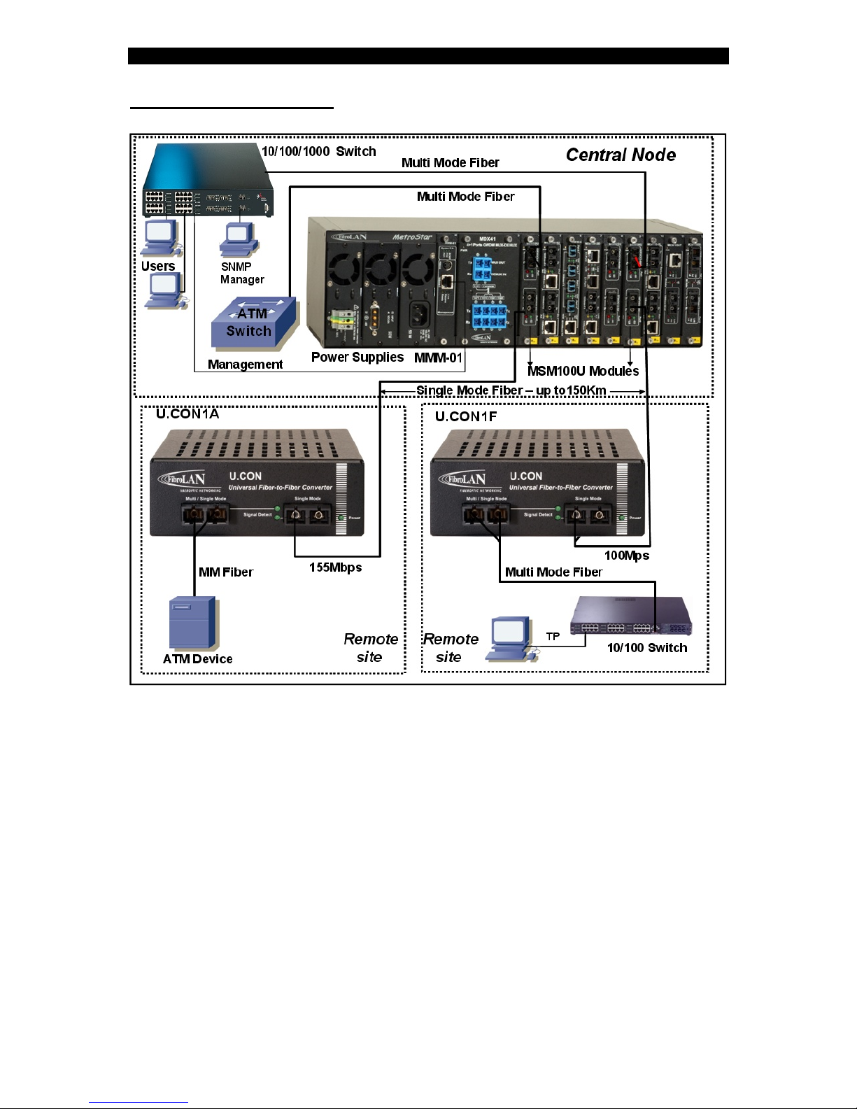
12 - Typical Network
The Central Node and the remote sites are interconnected by means of MSM100U
media converter modules installed in the FibroLAN MetroStar System and by the
remote FibroLAN U.CON1 converter devices.
These units are also stand-alone Universal Multi-mode to Single Mode Media
Converters (range: 25/40/70/100/150Km), supporting Fast Ethernet and ATM/OC3.
The MetroStar™ system equipped with an MMM-01 management module can
be monitored and managed from any SNMP management station running
popular management platforms (e.g. Fibro LAN’s MetroView, HP OpenView,
SNMPc, etc).

MSM100U Module Converter/Extender
13
13 - Troubleshooting
Before the implementation of the following procedure, ensure that the DIP slide
switches are in OFF position. Under management, perform "restore module
defaults" command.
Problem Indication Corrective Action
No power Module Power
LED (PWR) not
lit
Verify that the Power LEDs at the Power Monitor
module (or in the MMM-01 management module)
are lit, otherwise check that the MetroStar power
supply cables are firmly connected to the main
power supply.
Pull out the MSM100U module and reinsert it
back into another vacant MetroStar slot
Fiber link not working SD Signal
Detect LED
is not lit
Perform a Loop-back test on the suspected F/O
port. Verify that the correct fiber optic cables are
being used.
Recall that you are not allowed to perform
Loop-Back on both ports simultaneously.
Check that the receive fiber is properly connected
to the transmit port of the remote fiber device AND
the module transmit port to the receive port of the
remote device.
Check that the fiber optic power is higher than -
30dbm on the receive fiber connector at the
MSM100U module (or MSM622U module)
Verify that the output power of the transmitting port
of the remote attached device is within
manufacturer’s specifications
Improper network
traffic/ slowed down
traffic
Excess
collisions
Verify that all the interconnected devices are
operating with the same Duplex mode
If the problem persists after carrying out the above procedure, do the following: exchange your
MSM100U or MSM622U with another similar module believed to be functional, and re-perform
the requested check.
If that has solved the problem, send the faulty module for repair. If the problem still persists,
there is probably some sort of general network failure. Call your network support/administrator
9591718).
Make sure to provide the following information:
•Date and place of purchase, from whom, original invoice
•The serial number and Firmware revision of the MSM100U
•The configuration of the remote equipment that is connected to
the MSM100U module and the sequence of events leading to
the problem.
•Actions already taken
MSM100U Module Converter/Extender
14
14 - Specifications
Standard Compliance:
ATM-OC3, 100Base-FX
Conversion Method: Protocol Transparent
Fiber Optic ports specifications
Refer to the F/O port specifications in section 9 for all MSM100U
modules
Diagnostics:
Power LED
SD LED: Signal Detect for MM/SM Rx port 1
SD LED: Signal Detect for SM Rx port 2
LB LED: when lit indicates port 1 is in Loop-back mode
LB LED: when lit indicates port 2 is in Loop-back mode
DIP slide switches
S1: enable/disable Loop-Back – Port 1
S2: enable/disable Loop-Back – Port 2
S3: enable/disable the disconnect between F/O ports
Specifications subject to change without prior notice

MSM100U Module Converter/Extender
15
15 - Warrant Limitation
FibroLAN warrants the equipment to be free from defects in material and workmanship,
under normal and proper use and in its unmodified condition for 24 months (unless
otherwise agreed upon), starting on the date of delivery from FibroLAN to its distributor.
FibroLAN’s sole obligation under this warranty shall be to furnish parts and labor for the
repair or replacement of products found by FibroLAN to be defective in material or
workmanship during the warranty period. Warranty repairs will be performed at the point of
manufacture.
Following an authorized repair, the device shall be under warranty throughout its original
period but not less than 3 months. Warranty shall be void in case where unauthorized
attempts to repair/disassemble/modify the device is evident.
You must claim repairs or replacements under this warranty only from the reseller from which
you have purchased the device, however you may refer directly to FibroLAN Ltd. to claim the
warranty providing reasonable proof that the reseller ceased operation and/or unreasonably
refused to provide you with the service. In such case you provide to FibroLAN the serial
number of the device, date purchased, full details of reseller from whom the device was
purchase and a copy of an invoice or another proof of the purchase.
This document and the information contained herein are proprietary to the manufacturer and
are furnished to the recipient for use in operating, maintaining and repairing manufacturer
equipment. The information within may not be utilized for any purpose except as stated herein,
and may not be disclosed to third parties without the written permission from the
manufacturer. The manufacturer reserves the right to make changes to any technical
specifications in order to improve reliability, function and design.
This manual is applicable for the following Software and Firmware revisions:
MSM100U:
S/W (Software version): 1.2.5 onwards; F/W (Firmware version): 1.1 and higher
© COPYRIGHT 2004 FibroLAN Ltd. All rights reserved – Revision 2.0
(November 2009)
This manual suits for next models
13
Table of contents
Other FibroLAN Media Converter manuals


