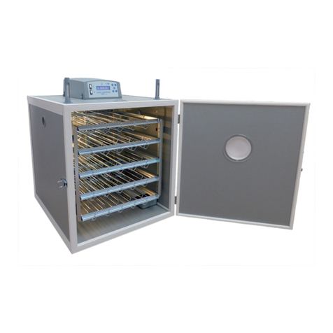
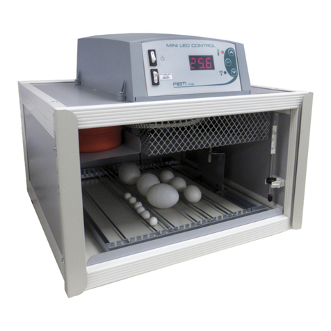
Fiem COSMO User manual

1
INSTRUCTIONS FOR INCUBATOR MOD. “COSMO &
COSMO EVO”
Cosmo represents, in any way, the new incubation frontier as each detail of this appliance has
been conceived to ensure excellent performance together with a unique and exclusive design.
It results from F.I.E.M. experience, reached and applied on field in years of dedicated research
and drilled down studies on incubation technique.
B E F O R E U S E
Before using the incubator, it is recommended to study the Instruction Manual, especially the
technical and safety data aspects, in order to gain an understanding of the components and the
potential operation of the machine.
MACHINE UNPACKING
Take the incubator out of its cardboard box and remove the internal components which are
secured by the adhesive tape and check that they are intact.
Check the following components are included:
• 1 no. adjustable egg turning grid;
• 1 no. mesh shelf;
• 1 no. dial hair hygrometer;
• 1 no. °F alcohol thermometer;
• 1 no. Instruction Book;
The incubator is supplied with a single phase electric cable (approx. 2 mt.) with a plug for the
electric connection 230V, 50/60 HZ.
On the back of the machine, the data plate gives full details regarding the voltage, power
requirements, registration number and production date.
IMPORTANT: Remember to check thermometer is working correctly, examining that there are
no breaks in the line of alcohol
.
POSITIONING AND PREPARATION
The area where the machine is placed should be well ventilated and dry, at a constant
temperature between 17 23 °C. Place the incubator on a flat, level surface and near to an
electric socket for easy access.
Use only the electric plugs supplied, with earth connection.
PLEASE NOTE: The manufacturer declines every responsibility in case of any improper use or
improper placement, connection to any unauthorized apparatus or tampering from unauthorized
personnel.
1. Before using the machine, remember to clean it carefully inside and outside, as shown in
the relative paragraph.
2. Insert the thermometer into its clip on the left side of the egg turning grid and adjust it so
that its bulb is level with the centre line of the eggs.

2
3. Natural surface humidification is performed by modular basins built into the machine lower
valve by an easy to use external filling system.
4. On the new developed VO Version the LCD electronic control unit can perform the digital
reading of humidity expressed in UR% (range 20-90%) and, if connected to an external
ultrasound humidifier, it is a super-modern digitally-regulated automatic humidification
system.
5. Insert the dial hair hygrometer into its metal support on the right frontal size.
6. Synthetic h ir hygrometer regener tion: in order to enable an exact humidity reading it’s
important at each incubation start to regenerate the dial hair hygrometer. A simple
regeneration is possible by storing the device several hours in wet atmosphere for instance
in bath rooms, wash houses or in the open air on humid foggy days or faster by wr pping
the device in wet towel for bout ½ hour. After this time the hygrometer must indicate a
relative humidity of max. 95 – 98%. Deviations can be corrected by turning the adjusting
screw with a small screw driver. The adjusting screw is visible through a small hole in the
back of the housing.
Once the machine has reached the working temperature place the eggs lying on the wire mesh
in horizontal position, between the rods of the adjustable egg turning grid.
When partially loaded of eggs check them to be closely positioned in the middle of the turning
grid to get the best possible movement of the same by proper egg weight distribution on the
turning grid.
To accommodate eggs of different sizes the Cosmo’s removable turning grid is supplied with
dividers which the user can position to suit their eggs.
ATTENTION: the correct working temperature for Cosmo model is fixed to 99,7°F
(corresponding to 37,7°C)
USE AND CALIBRATION
Plug the incubator into the electric power and allow the machine to run at the correct
temperature before setting the eggs.
The analogue thermostat (LCD for the EVO version see instructions for the calibration on the
next paragraph) , placed on the top valve, has been set up by the factory and indicates when
the machine is working (the led power results lighted). The continuous or intermittent lighting of
the led – ON – points out the heating activation.
Check that the set temperature on the thermostat dial agrees with the reading on the alcohol
thermometer inside the incubator. If necessary, adjust the set temperature slightly by using a
screwdriver in the central white screw on the thermostat box until the thermometer reads
99,7°F. It’s important to check the temperature on the thermometer in the incubator.
IMPORTANT : if all instrument setting attempts result useless, do not remove absolutely the
thermostat from its place to effect any improper or not authorized operation, just contact the
builder for a possible reparation or substitution.

3
The inside lighting of the machine is by an incandescent lamp activated by the switch placed on
the control panel; remember to switch off the light while the machine is in operation.
In order to activate the automatic turning of eggs ensure that the peg on the turner motor is
inserted into the metal stirrup connected to the egg grid.
Remember to turn the eggs twice per days, morning and evening, by the key on metal turning
grids, if the machine were supplied with manual egg turner.
Remind that on the hatching period (last two days) it will be necessary to stop the automatic
turning of eggs simply disconnecting the egg grid metal stirrup by the turner motor metal peg.
It’s not necessary to remove the full egg grid by the machine.
FIEM LCD CONTROL PANEL
The new FIEM LCD control system provide a range of useful and easy to use extra features
like temperature and humidity control by proportional, integrative and derivate system (PID)
and temperature alarms.
When switched on the control system displays for some seconds the software version.
The electronic control unit with backlit LCD will show at the same time the operating
temperature & humidity set up by the user along with the effective values of temperature and
relative humidity measured by the probes.
Ventilation intensity is fully and digitally adjustable according to the different incubation phases.
DESCRIPTION:
Temperature
reading
Relative humidity
reading
Fan speed set
value
Temperature
set point
Speed fan
regulation
Mode
(option on
demand)
t
Increase
Parameters
selection
Decrease
u
Relative
humidity set
point
Master
switch
Light switch

4
In case of any error on temperature or humidity reading two asterisks (**) will appear on the
display.
The electronic instrument has two setting parameters menus ; the first one allows the user to
adjust the main functions where possible and the technical one allows the instrument
configuration.
User menu
The operating temperature of the PID system, the high temperature alarm limit and the relative
humidity can be easily adjusted entering into the user menu by pressing the SET key.
It’s possible to view all parameters by pressing the SET key and to change the setting, by
pressing the keys “INCREASE”
e “DECREASE”
and confirming with SET.
If no keys are pressed for 25 seconds or longer, the electronic instrument will go out
automatically from program menu.
User menu p r meters list
• Unit Measur temp [°C,°F] (default °C)
Celsius / Fahrenheit degrees instrument setting
• Incubation temp. (default 30.0)
This parameter determines the operating temperature during incubation period. The
range of possible temperature setting values is limited by the parameters
“Inc.temp.min.” and “Inc.temp.max.” shown in the technical menu.
• Alarm temperatur (default 40.0)
When the maximum temperature limit set up by the user in this parameter is reached,
the emergency relay will be switched on in order to warn temperature abnormalities.
This output will remain active until the temperature drops below the set value –
“Ist.temp.allarm.”.
The range of possible temperature setting values is limited by the parameters
“Temp.alarm.min.” and “Temp.alarm.max.” shown in the technical menu.
• Incubation humid (default 40)
This parameter allows relative humidity settings during incubation period. The range of
possible humidity setting values is limited by the parameters “Min.humidity” and
“Max.humidity” shown in the technical menu.
Speed f n regul tion
Press the “Fan” key to enter the fan speed set up page, choose the set value 1,2 or 3 by the
keys
and
and confirm by pressing again the “Fan” key.
Speed 1= lower fan speed suggested for breeding live animals in the first week of life.
Speed 2= medium fan speed suggested for hatching period (last 2 days)
Speed 3= maximum speed suggested during incubation period

5
Technic l menu
Pressing simultaneously both keys
+
, you will access the “Technical menu”.
To view a set value press the “ SET key and, if required, change it by using the keys
and
and memorize by “set”.
The electronic instrument will automatically exit the programming menu if no keys are pressed
for longer than 25 Sec.
Technic l menu p r meters list
• Unit Misura temp [°C,°F] (default °C)
Celsius / Fahrenheit degrees instrument setting
• Inc. temp. min. [5,0 .. 75,0] (default 25.0)
Used to limit the minimum acceptable temperature value in the “incubation parameter”
on the User Menu
• Inc. temp. max. [5,0 .. 75,0] (default 40.0)
Used to limit the maximum acceptable temperature value in the “incubation” parameter”
on the User Menu
• Alarm temp. min. [5,0 .. 75,0] (default 30.0)
Used to limit the minimum acceptable value in the parameter “alarm temperature” on the
User Menu
• Alarm temp. max. [5,0 .. 75,0] (default 40.0)
Used to limit the maximum acceptable value in the parameter “alarm temperature” on
the User Menu
• Alarm temp.hyst. [0,1 .. 5,0] (default 0.1)
Used to set up with the maximum accuracy the alarm temperature
hysteresis
• Calib temp.probe [ 3,0 .. +3,0] (default 0.0)
Used to calibrate the temperature value detected by the probe
• Humidity minimum [10 .. 90] (default 40)
Used to limit the minimum acceptable value in the parameter “incubation humidity” on
the User Menu
• Humidity maximum [10 .. 99] (default 80)
Used to limit the maximum acceptable value in the parameter “incubation humidity” on
the User Menu
• Humidity hyst. [1 .. 20] (default 1)

6
Used to set up with the maximum accuracy the humidity regulation hysteresis
• Cal.humid. probe [ 5 .. +5] (default 0)
Used to calibrate the humidity value detected by the probe
• Language [0 .. 1] (default 0)
Used to select the languages shown on the display (Italian / English)
• Type of fan [1 .. 4] (default 1)
Used to set up the fan motor type controlled by the instrument
• Buzzer Mode [0 .. 2] (default 2)
Used to set up the buzzer operating mode.
.
• 0 = Buzzer off
• 1 = Buzzer on when pressing keys
• 2 = Buzzer on when pressing keys and in case of high temperature alarm
HUMIDITY
Natural surface humidification is performed by modular basins built into the machine lower
valve by an easy to use external filling system.
On the new developed VO Version the LCD electronic control unit can perform the digital
reading of humidity expressed in UR% (range 20-90%) and, if connected to an external
ultrasound humidifier, it is a super-modern digitally-regulated automatic humidification system.
It is important to understand that there can be no hard and fast rule for the amount of water
required in an incubator as the following variables come into play:
• Ambient humidity in the room (affected by the weather and your local environment).
• The species of the eggs
• The porosity of the eggshells (can vary from egg to egg)
• The time of year (warm weather usually means high ambient humidity and eggs laid
towards the end of the season tend to be more porous)
Requirement for water in the incubator can be monitored by either weighing the eggs (an egg
should loose 13 15% of its weight during incubation) or by candling (the air space should be
approx. 1/3 of the egg by the time it is due to hatch).
On subsequent hatches you may wish to increase or decrease the amount of water, depending
on your findings with your first hatch. If in doubt, it is better to dd too little w ter th n too
much – more eggs re lost through too high humidity th n ny other single f ctor!
Remember, the depth of water makes no difference to the humidity levels in the incubator; it’s
the surface area which counts!
LOAD EGGS STORED NOT MORE THAN 7- 8 DAYS AND NOT LESS THAN 3 DAYS FROM LYING.
BEFORE
INCUBATION,
THE
EGGS
MUST
BE
STORED
IN
A
LOCATION
WITH
TEMPERATURE
BETWEEN
14
–
16
°C.

7
In order to regulate the humidity level inside the machine it is important to remind that enlarging
the water surface humidity % increases and contrarily reducing the water surface area humidity
decreases.
APPROX. HUMIDITY VALUES WHEN OPERATING AT 37.7°C (100°F) DRY BULB TEMPERATURE
TYPE INCUBATION HATCHING
HEN LIGHT BREED(LAYER)
82°F = 47% 88°F = 62%
HEN HEAVY BREED (BROILER) 84°F = 52% 88°F = 62%
PHEASANT PARTRIDGE – QUAIL RED LEG PARTRIDGE 78 80°F = 38 43%
86 88°F = 56 62%
TURKEY – GUINEA FOWL
82 84°F = 47 52%
88°F = 62%
GOOSE DUCK (MALLARD,PEKIN, KHAKI CAMPBELL, WILD) 78 80°F = 38 43%
88°F = 62%
OSTRICK (CAMELUS)
70 74°F = 25 30%
78 80°F = 38 43%

8
EGG-CANDLING
At 8th 10th day of incubation, it is advisable to candle the eggs in order to eliminate those
which are infertile; this operation must be done in a dark room. By observing the inside of a
developing, fertile egg, using a suitable candling lamp, it is possible to determine the embryo
development which looks like a small reddish shape, composed of the heart and small arteries
which are radiating from it (Fig. b).If the egg is moved lightly, it is possible to see clearly the
rhythmic oscillations of the embryo.
On the contrary, an infertile egg appears completely transparent (clear), with a slight darkening
where the yolk is. (a).
If during the candling operation, you find some eggs with a reddish spot stuck or attached to the
shell, or a central spot surrounded by one or more concentric hoops, or something nebulous
crossing the inside; then in this case, the embryos are either false or dead, and must be taken
out of the incubator to prevent them contaminating other eggs with bacteria by infection or
explosion
a) Infertile egg
b) Egg with normally developing embryo
c) Egg with dead embryo at 5th 6th day of incubation
Periodic candling during embryonic development is necessary to ensure the best hatching
results. Using a good candling lamp, it is possible to check the growth of the air space. The
pictures shown herewith show the air space growth as related to hen, turkey, and pheasant
eggs. If the air space measurements appear similar to those shown in the picture, it means that
the embryo is developing correctly, and that the amount of humidity supplied in the machine is
right.
If the air space is not developing correctly, it means that it is necessary to change the level of
humidity supplied to the machine.
1
1
It must be noted that when the air space is smaller than shown in the table, it is necessary to decrease the humidity value;
when the air space is larger than shown in the table, the humidity must be increased.
1
st
day
8
th
day
16
th
day
21th day
1
st
day
7
th
day
14
th
day
19
th
day
1
st
day
10
th
day
15
th
day
20
th
day
24
th
day
Pheasant egg
hen egg
turkey egg

9
DESCRIPTION
1 LCD control panel (mod. EVO) 10 Alcohol thermometer (°F)
2 Analogue control panel 11 Temperature sensor
3 Exhaust hole 12 Humidity sensor (mod.EVO)
4 Protection wire net 13 Fan motor
5 Dial hair hygrometer 14 Silicon heating cable
6 Egg turning motor 15 Main switch & light switch
7 Adjustable egg turning grid
16 Transparent door
8 Wire net floor
17 Lighting lamp
9 Modular humidification basins
1
2
3
4
5
16
7
8
9
10
11
12
13
6
17
14
15

10
H E L P F U L S U G G E S T I O N S
• In case of power failure for some hours during the incubation time, place one hot water bottle
or similar container into the machine and keep the door closed
2
.
• For waterfowl eggs, after 15 days of incubation, it is suggested that the eggs should be
taken out of the incubator and sprayed with tepid water (using a suitable hygienic sprayer)
and leave them to cool for about 15 minutes outside the machine. This operation should be
repeated every two days, till the penultimate day of incubation.
• It’s recommended that the incubator room should be clean and hygienic, in order to obviate
any bacteriological infection.
• It should be remembered that during incubation and hatching there is a constant risk of
bacterial contamination and the following precautions are therefore recommended:
Use of personal protective clothing (i.e.: disposable plastic gloves, protective respiratory
mask);
Regular cleaning and disinfection of incubation rooms;
Careful cleaning of hands before and after the contact with organic parts using antibacterial
gel soap.
Avoid eating or serving food and drink in the incubation room or during the operation of the
machine.
(These suggestions are extremely important in order to afford maximum protection to both eggs
and operator)
Egg he lth nd hygiene
To maximise fertility and to avoid contamination during the incubation period, please follow
the directions below when collecting eggs:
- Collect the eggs daily to avoid contamination or loss from breakage or damage, caused by
hot or cold temperatures (winter and summer periods).
- Clean hands before and after egg collection with anti bacterial soap.
- LOAD EGGS STORED NOT MORE THAN 7 8 DAYS AND NOT LESS THAN 3 DAYS FROM
LYING.
- BEFORE INCUBATION, THE EGGS MUST BE STORED IN A SPECIFIC EGG BASKET (IN
VERTICAL POSITION WITH THE AIR SPACE FACED UPWARDS) WITH TEMPERATURE
BETWEEN 14 – 16 °C.
- Do not mark the eggs with felt tip pens – use only pencil
MODEL “COSMO”
POWER SUPPLY V/Hz 230 / 50
POWER CONSUMPTION Watt. 185
DIMENSIONS mm 640 x 530 x 400
NET WEIGHT Kg 9,5
EGGS CAPACITY Hen Mallard 70 72
Pheasant 96 104
Partridge Quail 150 180
Turkey Duck 62 64
Goose 30 36
2
The lack of power for an extended time causes more serious damage to eggs which are only a few days into incubation than
to those which are more advanced, when the embryo is stronger and more resilient.

11
INCUBATION PERIOD OF THE DIFFERENT SPECIES
SPECIE
DAYS
SPECIE
DAYS
HEN
21
PEKIN DUCK
27 28
QUAIL
16 17
WILD DUCK 25 26
TURKEY
28
BARBARY DUCK
34 35
GUINEA FOWL
26
RED LEG
23 24
PARTRIDGE
23 24
PHEASANT
24 25
GOOSE
30
BOB WHITE
22 23
C A R E A N D M A I N T E N A N C E
In order to achieve the best operation and longest life of the machine, follow the following
precautions:
• do not expose the machine to outdoor elements
• do not place machine in hot, wet or cold rooms;
• avoid bad handling during moving that can cause breakages inside the machine and
affect its working;
• disconnect the power plug before cleaning the machine;
• Do not accidentally pull out the power cable when moving the machine.
IMPORTANT:
take out the plug from the socket by holding the plug and not the power
cable; use only a mains power socket or surge protected extension lead.
• for cleaning and disinfection please follow the advice as follows :
HOW TO CLEAN THE INCUBATOR:
For a good hygiene during the incubation, it is recommended to clean the machine before
and after its use;
Use a wet cloth on the machine with a light disinfectant; do not use solvents that can
damage the machine cabinet;
Clean the base of the machine with a normal domestic detergent.
ADVICE: after cleaning the machine, please keep it working without eggs & water for at
least two hours (with the door semi closed), in order to dry the humidity which has
accumulated during the incubation period... This will ensure the correct machine operation
for the next use.

12
INSTRUCTIONS FOR LIGHT BULB REPLACEMENT:
a) Buy small bulb only (pear shape) of 15W with an E14 screw fitting;
b) Remember to switch off the m chine nd disconnect the power c ble from the
current socket nd le ve the l mp cooling in order to void ny sc lding;
c) Use a star screwdriver and unscrew the screw;
d) Take out the wire mesh on the bottom of the machine;
e) Unscrew the broken lamp in anti clockwise direction ( be careful with those exploded or
broken);
f) insert the new lamp, screwing it carefully in clockwise direction;
g) Put the mesh back again inside, screwing carefully the screw.
WARRANTY
Each part of the machine has been fully tested by the manufacturer before delivery or
shipping.
The manufacturer’s guarantee does not include damage caused by improper transport
and does not include damage to the electrical and electronic systems caused by incorrect
connection to the power supply.
The guarantee includes repairs or replacement of all the parts that are found to be
defective in the 24 months (12 months by the manufacturer + 12 months by the seller)
following the delivery of the machine to the customer and applies when the customer
informs the manufacturer, no later than the eighth day from when the fault occurred.
This Guarantee refers to possible defects in workmanship and it is excluded in any case
of improper use, improper placement and connection or in any case of tampering from
unauthorized personnel.
The guarantee includes all technical telephone support, but the customer is liable for all
shipping costs for sending all defective parts to be replaced to FIEM and all technical call
out costs.
The gu r ntee does not include ny compens tion for ny downtime of the
m chine or d m ges incurred during use.
Only st ff uthorised by the m nuf cturer must be llowed to c rry out rep irs
under the gu r ntee; if this cl use is not dhered to, the gu r ntee will ce se to
pply.

13
STANDARDS OF REFERENCE
This product conforms to the essential Electromagnetic and safety requirements foreseen by
the following directives:
• 2004/108/CE del 15 Dicembre 2004
• 2006/95/CE del 12 Dicembre 2006
As projected in conformity to the prescriptions of the following Harmonized Rules:
EN 55014 1: 2006
EN 55014 2: 1997+A1:2001
EN 61000 3 2: 2006
EN 61000 3 3: 1995+A1:2001+A2: 2005
EN 60335 2 71:2003+A1:2007
Conformity to the above requirements is attested by marking on the product;
The mark was introduced in 1995.
It is opportune to underline the following actions that can prejudge the conformity and moreover
the product characteristics:
• incorrect electricity supply;
• incorrect installation or incorrect /improper use or not conforming to the instructions reported
in the instruction book supplied with machine;
• replacement of its components with those not approved or adopted by the manufacturer, or
replacement effected by unauthorized technical service.
• WARNING: THIS EQUIPMENT MUST BE EARTHED
• ATTENZIONE: QUESTA UNITA’ DEVE ESSERE CONNESSA A TERRA
• ATTENTION: CETTE UNITE’ DOIT ETRE MISE’ A LA TERRE
• ACHTUNG: DIESES GERAT MUSS EINEN ERDUNGSANSCHLUSS HABEN.
• ATENCION: ESTE EQUIPO DEBE ESTAR CONECTADO A UNA TOMA DE TIERRA.
• APPARATET MA KUN TILKOPLES JORDET STIKKONTACT. APPARATEN SKALL
ANSLUTAS TILL JORDAT NATUKKAT. LAITE ON LITTETAVA SUKO RASIAAN.

14
DECLARATION OF CONFORMITY
of the tt chement II, p rt. 1 section A of DL/17/2010/CE
M nuf ctured in the EU for:
Incub trici F.I.E.M. S.n.c. di Tin Luccini & C.
Via G.Galilei, 3 – 22070 Guanzate (Como) Italy
D E C L A R E S T H A T
THE MACHINE Incubator
MODEL Cosmo Cosmo EVO
SERIAL NUMBER
IS MANUFACTURED AND SOLD IN CONFORMITY TO THE ESSENTIAL
REQUIREMENTS OF HEALTH AND SAFETY
of D.M. 17 of 17 J nu ry 2010 – Att chement I (implement tion of the M chinery Directive
2006/42/EC)
The met llic pl te fixed on the m chine is n integr l p rt of the s me;
ll seri l numbers, nd product specific tions re det iled on the pl te.
THE FOLLOWING HARMONIZED RULES HAVE BEEN UTILIZED FOR THE CORRECT
IMPLEMENTATION OF THE ESSENTIAL REQUIREMENTS OF HEALTH AND SAFETY OF
THE ATTACHEMENT I.
EN ISO 12100 1
EN ISO 12100 2
EN ISO 14121,
EN ISO 13857
Gu nz te (Co) The Decl rer
____________________________

15
TROUBLE SHOOTING CHECK LIST
Before asking for a technical assistance service, please follow this list to try to solve most
common problems:
PROBLEM CAUSE SOLUTION
The machine does not work
Lack of power Check the plug
Plug disconnected Put the plug into the socket
Master switch “0/I” on position “0” Position the switch on “I”
Thermal fuse burnt Replace the thermal fuse
Any of the above points Contact the assistance service
Working temperature
not sufficient
Heating element not correctly
working
Contact the manufacturer
Thermostat not calibrated See instruction for calibration
Thermostat faulty or not working Contact the manufacturer
Door open or incorrectly closed Close the door
Egg turner device not
working properly
Egg turner motor broken Contact the manufacturer
Egg turning grid not connected to
the egg turning motor metal peg
Connection the turning grid metal
stirrup to the peg of the egg
turning motor
Forced ventilation not
sufficient
Fan not working
3
Contact the manufacturer
Interior lighting not working Switch on “0” position Place the switch on “I” position
Lamp burnt Replace the lamp as shown in
the instructions
Dial hair hygrometer not
working properly
Dial hair hygrometer improperly
calibrated
Follow the instructions regarding
synthetic hair hygrometer
regeneration contained on the
“positioning & preparation”
paragraph.
Whichever reparation attempt not included on above mentioned form is severely forbidden.
Contact always the manufacturer or the authorized technical assistance in your country.
Fiem s.n.c. di Tin Luccini & C.
Ph : 0039 (0)31 976672
F x : 0039 (0)31 899163
fiem@fiem.it www.fiem.it
3
Correct working of the fan should be checked visually, faulty operation of the fan could compromise
incubation results.

16
WIRING DIAGRAM
Other manuals for COSMO
1
This manual suits for next models
1
Table of contents
Other Fiem Accessories manuals
Popular Accessories manuals by other brands
Leuze electronic
Leuze electronic MC3 Series manual
Victron energy
Victron energy Smart Battery Sense manual
PCB Piezotronics
PCB Piezotronics 320C15 Installation and operating manual

Icemoon
Icemoon Hidden Camera Power Bank user manual
Elkay
Elkay LZO Series Installation, care & use manual

A-Safe
A-Safe RackEye User's product manual


