Fiessler ULVT User manual

BG
zugelassen
Z
e
r
t
i
f
i
z
i
e
r
t
ISO 9001
DIN EN ISO 9001
ISO 9001: 2008
C
e
r
t
i
f
i
e
d
Infrared accident prevention safety curtains ESPE Type 4
ULVT
BLVT
ULVTK
BLVTK
INHALT:
Safety instructions
Application notes
Installation
Electric Connection
Commissioning
Specifications Accessories
FIESSLER
E L E K T R O N I K
ULVT BLVT (with blanking features)
Muting, cycle operation .... with safety switching units as option
ULVTK / BLVTK (Cascading of Light Curtains)
Operating instructions
translation
1
23
5
4
Phone: +49 (0) 711 / 91 96 97-0 Internet: http://www.fiessler.de
Fiessler Elektronik GmbH & Co. KG Doku Nr. 958 Stand 22.01.2018 RK

For over 50 years,
we have proved to be specialists in the area of optoelectronics.
Our experience is your gain. Tell us your problems, and we will be
pleased to advise you.
Area laser Scanner Singel-Beam safety light bar-
rier with extended range (up
to 150 m)
Press Brake Protection Sy-
stem AKAS®
Safety switching mats Differentiation between man
and machine by the use of
the Muting function
3- and multi-beam light grid
range until 60 m
two-beam light grid with
transmitter/receiver unit and
mirror unit, range up to 10 m
Outgoing muting
Differentiation between man
and material
two-beam light grid
range until 60 m
Cross muting
Differentiation between man
and machine / material
Fiessler Elektronik GmbH & Co.KG
DE-73773 Aichwald
Phone: ++49(0)711-91 96 97-0
Fax: ++49(0)711-91 96 97-50
Email: [email protected]
Internet: www.fiessler.de
Representations in all major industrial nations.
FIESSLER
E L E K T R O N I K
Roboter
MUTINGLAMPE
Palette
Roboter
MUTINGLAMPE
Palette
We also invest in environmental protection
2
Fiessler Elektronik GmbH & Co. KG Doku Nr. 958 Stand 22.01.2018 RK Phone: +49 (0) 711 / 91 96 97-0 Internet: http://www.fiessler.de

Sector Contents Page
1 Safety Instructions 5
1.1 Prerequisites for the utilisation of the safety light curtains 5
2Terminology 6
3 System Description and Technical Data 8
3.1 Features 8
3.2 Application Areas 8
3.3 Structure and Function 9
3.4 Tables: Protective fields,constructional lengths, ranges, resolutions, beam spacing, number of beams 9
3.5 LED-displays (in general) 10
3.6 Operating modes selector (with/without restart interlock, with/without contactor check, equivalent/antivalent outputs) 10
3.7 Technical data 11
3.8 Dimensions drawing (Light curtain and standard fastening brackets) 12
4 Installation 13
4.1 Response times ULVT, BLVT, cascaded systems and optional safety switching units 13
4.2 Safety distance from the hazardous areas 14
4.2.1 - vertical protection for hazardous areas (≤40 mm resolution) 14
4.2.2 - horizontal protection for hazardous areas 15
4.2.3 - vertical protection for hazardous areas by light grids (> 40 mm resolutiion and single beams) 16
4.3 Construction requirements 17
4.3.1 - Installation without additional screening 17
4.3.2 - Protection against reaching over or under barriers 17
4.3.3 - Protection against avoiding barriers through cascading or additional screening 17
4.3.4 - Distance from reflective surfaces 18
4.3.5 - Arrangement of two safety light barriers 18
4.4 Mounting and Adjustment 19
4.4.1 Adjustment Instructions with standard fastening brackets / Isolated mounting on EMV disturbances 19
4.4.2 Option: angular brackets (dimension drawing included) 20
4.4.3 Option: rubber-metal connection (to avoid intense vibrations) 21
4.4.4 Option: multi-sided screening by using tilted mirrors (dimension drawing included) 21
4.4.5 Option: Assembly columns / Shock Protection (dimension drawing included) 23
5 Electric Connection ULVT / BLVT 25
5.1 Integrated connector plug 25
5.2 Electric connection ratings 25
5.3 Connectors 25
5.4 Connection examples - without optional safety switching units 26
5.4.1 ULVT 500/2R: connecting advice 26
5.4.2 Safety mode with restart interlock/ with valve or contactor check 26
5.4.3 Safety mode without restart interlock/ without valve or contactor check 26
5.4.4 SPS drive 26
6Commissioning 27
6.1 Commissioning 27
6.2 Adjustment instructions / LED-displays 27
6.3 Trouble-shooting / LED-displays 28
chapters 7 ... 11 --->>
Table of contents
FIESSLER
E L E K T R O N I K
3
Fiessler Elektronik GmbH & Co. KG Doku Nr. 958 Stand 22.01.2018 RK Phone: +49 (0) 711 / 91 96 97-0 Internet: http://www.fiessler.de

chapter contents Page
7BLVT-Blanking functions (Blanking) 29
7.1 Safety Advices 29
7.2 Typical applications of the different blanking functions 30
7.3 Important instructions and available resolutions of the different blanking functions 31
7.4 Programmer units for programming the blanking functions 32
7.5 Programming up to 5 different blanking patterns and activating them via selector switch 32
8Cascading of Light curtains 33
8.1 Additional safety advices tor cascaded Light grids 33
8.2 Application examples 33
8.3 How to utilize and to combine the systems (Cat. 4 und Cat. 2 ) 34
8.4 Order designations 34
8.5 Response time (examples) 35
8.6 Safety distance (example) 35
8.7 Installation 36
8.8 Connection 36
8.8.1 Connection example 1 36
8.8.2 Connection example 2 37
8.9 Commissioning 38
8.10 Commissioning / Protective Field States and LED- Displays 39
9 Additional functions with safety switching units 40
10 Accessories and Spare Parts 41
11 Notes 42
12 Service / Maintenance / Warranty 46
13 Declaration of conformity 47
14 Additional safety products 48
Table of contents
FIESSLER
E L E K T R O N I K
4
Fiessler Elektronik GmbH & Co. KG Doku Nr. 958 Stand 22.01.2018 RK Phone: +49 (0) 711 / 91 96 97-0 Internet: http://www.fiessler.de

All safety instructions are marked with this symbol and must be observed under all circumstances!
1.1 Prerequisites for the utilisation of the safety light curtains:
1Safety advice Please observe!
The unintentional repetition of a hazardous movement
must be prevented by the appropriate safety facilities.
-The safety category (Type 4) of the accident-prevention
light barrier should be at least the same as safety category
of the machine.
Approval:
Approval of the construction and the tests should be
carried out by competent personnel who are in possession
of all information provided by the supplier of the machine
and the BWS.
Annual inspection:
The operator must ensure that a competent person is
assigned with the task of inspecting the light barrier on a
yearly basis. This person may, for example, comprise an
employee of the light barrier manufacturer or of the
operator.
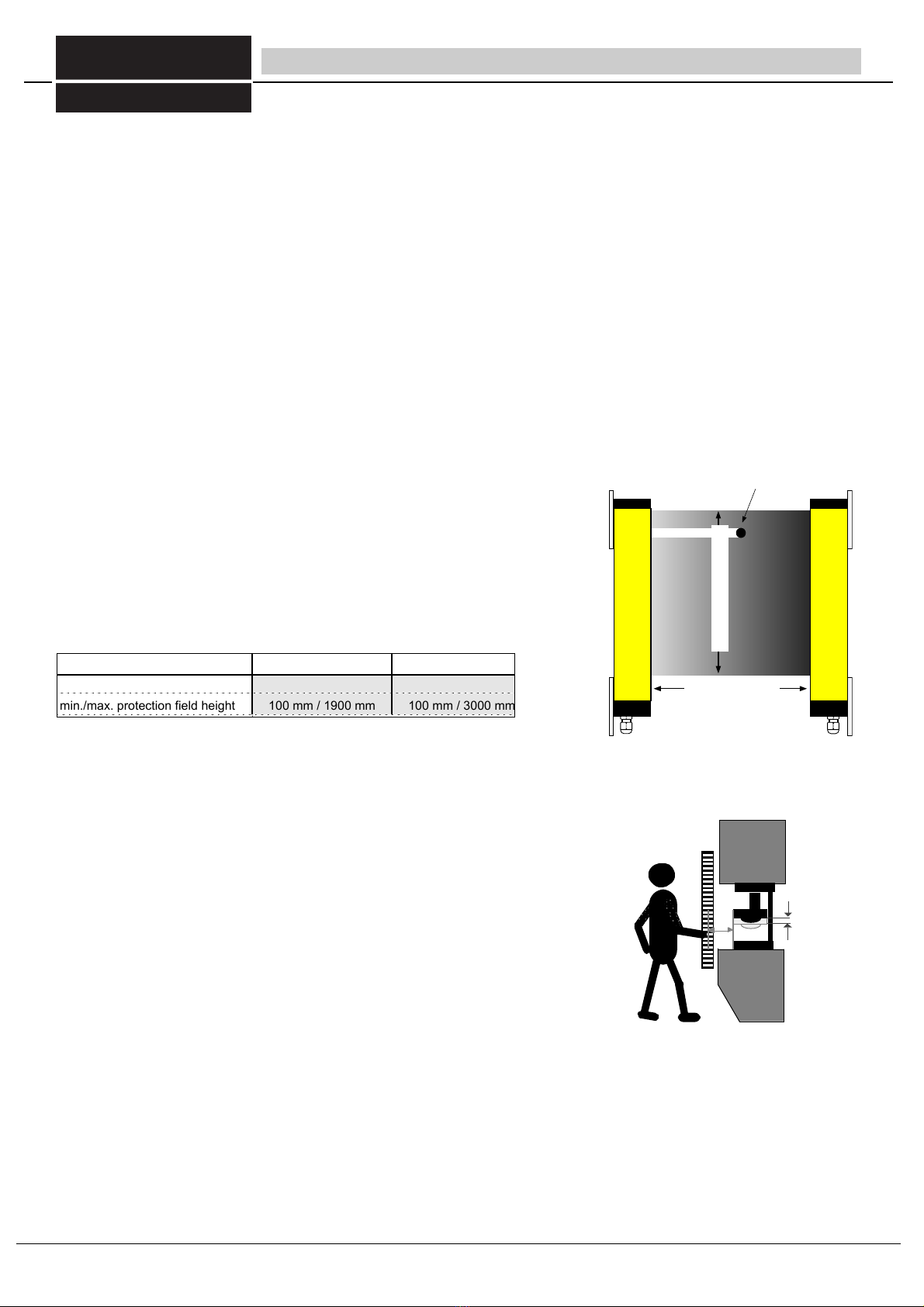
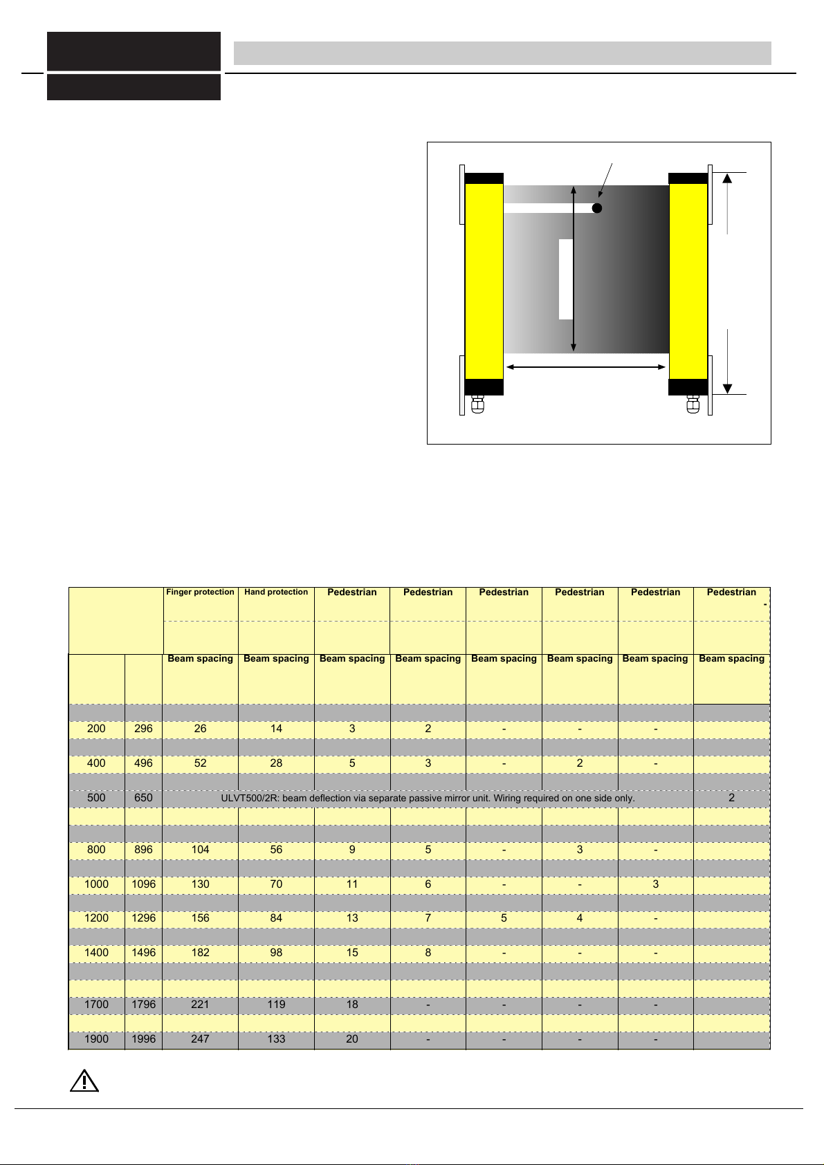
The safety distance between the protective field and the
hazardous area must be large enough to ensure that when
penetrating the protective field, the hazardous areas cannot
be reached before the hazardous movement is interrupted
or ended.
Access to the hazardous area must only be possible
through the protective field (reaching under, over or around
the field must not be possible).
Passing through the light barrier must only be possible if
the restart interlock is activated subsequent to the light
barrier being interrupted.
A new command to activate the next hazardous movement
must only be implemented via a dead-man switch. It must
not be possible for this start button to be actuated from
within the hazardous area: The switch must be located at a
point from which the accessible area can be viewed without
obstruction.
The hazardous state of a machine must be interrupted by
the sensory function of the ESPE.
The safe operation of the entire system can only be ensured through adherence to these operating
instructions and the corresponding accident prevention regulations.
These operating instructions comprise part of the light barrier and must be retained at the installation site.
All specifications of these operating instructions must be observed at all times. These operating instructions provide the
user with important information concerning the proper use of the ULVT/BLVT safety light barriers. .
When using safety light barriers, the effective standards and guidelines must be observed! The local authorities or
trade associations will provide you with the relevant information. Currently effective conditions and the regulations of the trade
associations must also be adhered to.
Qualified personnel. Installation, commissioning and maintenance must only be carried out by qualified personnel.
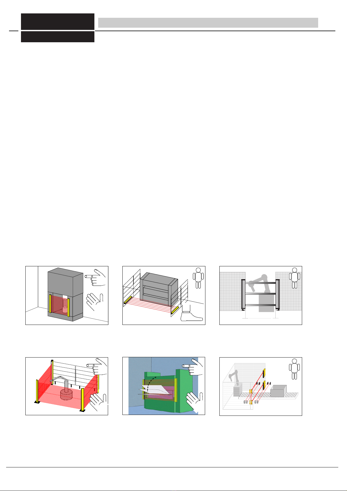
Danger sign When operating a machine with ULVT/BLVT ... safety light barriers, it must be ensured that nobody is located
within a hazardous area. A danger sign to this effect must be attached to the machine.
Light barriers do not provide protection from flying objects resulting from the operation of the machine.
When using the ULVT/ BLVT with an external switching unit or similar succeeding controls, it must be ensured by ap-
propriate, either contructional or organisatorial means, that at least once within 24 hours, a close-down of the light curtain by
intentional interruption ot testing of the protective field takes place in order to prevent any unnoticed accumulation of mal-
functions.
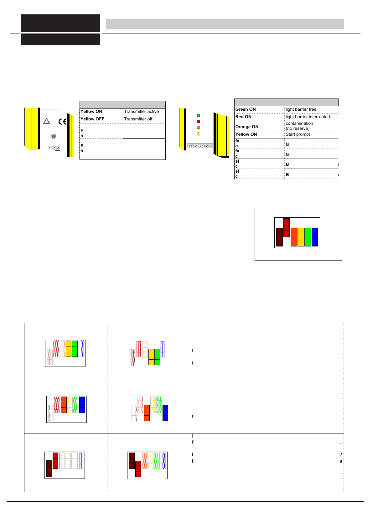
Caution, daily inspection (after 24 hours at the latest): Before the start of a shift, the light barrier must be checked as
follows: Using the test rod*, the light barrier is to be interrupted on the transmitting side from start to finish in such a way that
the light field is only covered by this part. The green LED (or the yellow LED in the operating mode with restart interlock) must
not light up from start to finish.
* The diameter of the test rod must correspond to the obstacle size specified on the nameplate of the receiving side.Acht
When using the BLVT Blanking features, the additional safety advices and all other instructions in chapter 7 must be
observed!
When using the Cascading features, the additional safety advices and all other instructions in chapter 8 must be
observed!
FIESSLER
E L E K T R O N I K
Maintenance information: The ULVT/BLVT... system is maintenance-free depending on the construction. (This does not,
however, release the obligation to carry out the prescribed annual inspection pursuant to EN 61496, ZH 1/281 and/or ZH 1/
597.) On request by the customer, the Fiessler Elektronik company will carry out the initial approval and annual
inspection. In addition, customer-training seminars concerning the implementation of the annual inspection are held at
regular intervals.
The protective panels in front of the transmitter and receiver should simply be cleaned at regular intervals with a solvent-free
detergent. Solvents can damage the plexiglass panels of the transmitter and receiver. As an alternative, light barriers with
silicate glass are available.
5
Fiessler Elektronik GmbH & Co. KG Doku Nr. 958 Stand 22.01.2018 RK Phone: +49 (0) 711 / 91 96 97-0 Internet: http://www.fiessler.de

Start interlock
Subsequent to commissioning and/or a power interruption, the start interlock prevents a "re-release". A re-release is only possible
once the protective field has been interrupted and reactivated.
Response time
The time period between penetration of the protective field and the switching process.
Blanking
Ther Balnking features provide the temporarily "skipping" or "disabling" of selected areas of the the protective field. By doing this,
parts of tools or machinery may reach into the protective field without reducing the function of the machine. (please refer top
chapter 7 BLVT).
EPSE Type 4
The ULVT/BLVT... safety light barriers comprise photo-electric guards. These devices are characterized by the fact that when the
protective field generated by the transmitter and receiver is interrupted, a hazardous movement is interrupted or prevented.
One-cycle (two-cycle operating mode)
Subsequent to one (two) penetrationsof the protectvie field, the machine automatically performs an operating cycle and then waits
for a maximum 30 seconds for one (two) penetrations.
If the time period exceeds 30 seconds, the restart interlock is activated.
Installation range (Fig. 6/1)
The minimum and/or maximum permissible distance between the transmitter and
receiver. The permissible detection range is specified on the ULVT receiver.
Obstacle size (Fig. 6/1)
The obstacle size indicates the minimum obstacle diameter that will definitely interrupt a
hazardous movement through the safety light barriers.
The following obstacle sizes are provided by the beam distances for the ULVT... safety
light barriers:
Muting
Temporary and safe bridging of the ULVT/BLVT safety light barriers during a material movement, e.g. into and out of a
manufacturing cell, or in high-bay storage. Reliable differentiation between man and material flow is ensured.
Overrrun
The section of hazardous movement which occurs after penetration of the protective field.
Overrrun traverse (Fig. 6/2)
The path traversed during the run-on period (e.g. path of a ram, path of a point on a roller
surface).
Overrrun period
Duration of the run-on period.
Protective field height (Fig. 6/1)
Height of the protective field generated by the transmitter and receiver.
Safety mode
When the protective field is interrupted, the switching outputs are blocked, then automatically released subsequent to re-release
of the protective field.
Self-monitoring
The automatic response of the photo-electric guard in the event of an internal malfunction.
Safety distance (Fig. 30/2)
The minimum distance S between safety light barrier and the nearest hazardous area, required in order to prevent injuries. In
order to establish the minimum safe distance, the formulas from standard EN 999 / ISO 13855, the machine-specific EC
standards and the effective ZH guidelines are to be used.
min./max. detection range 0,3 m / 7 m 0,3 m / 24 m
min. obstacle diameter
min./max. protection field height
14 mm
100 mm / 1900 mm
30 mm
100 mm / 3000 mm
S
Nachlaufweg
der Maschine
2Terminology
protective field height
detection range
obstacle diameter
Bild 6/2 Ssafety distance and overrun traverse
fig 6/1 detection range, obstsacle size, protective fied height
Table 6/1a detection range, obstsacle size, protective fied height
Overrun
traverse of
the machine
FIESSLER
E L E K T R O N I K
6
Fiessler Elektronik GmbH & Co. KG Doku Nr. 958 Stand 22.01.2018 RK Phone: +49 (0) 711 / 91 96 97-0 Internet: http://www.fiessler.de

Safety category 4
The ULVT safety light barriers belong to safety category 4 as per EN 945-1 and IEC 61496 / EN 61496.
Devices of safety category 4 comprise self-monitoring photo-electric guards and represent the highest safety class for photo-
Beam spacing
The distance (gap) between the centres of the individual lenses on ULVT/BLVT... safety light barriers is called the beam distance/
beam spacing. The ULVT/BLVT... safety light barriers are supplied with a lens grid of 7.5 mm, respective and 14mm.
Valve or contactor control
Prior to each release of the switching outputs, the contactor control identifies whether the connected switching elements (relays,
contactors or valves) have fallen. Only when this is so can a new release of the switching inputs be performed. This also prevents
the dangerous failure of the switching elements (relays, contactors, valves) of the hazardous movement.
Restart interlock
The restart interlock prevents the automatic release of the switching outputs subsequent to the interruption and reactivation of the
protective field (e.g. due to walking through the protective field).
2Terminology
FIESSLER
E L E K T R O N I K
7
Fiessler Elektronik GmbH & Co. KG Doku Nr. 958 Stand 22.01.2018 RK Phone: +49 (0) 711 / 91 96 97-0 Internet: http://www.fiessler.de

Bild 8/1 Protecting in hazardous areas Bild 8/2 cordoning off areas Bild 8/3 Restricting access to areas
3System description - Features and Application Areas
Bild 8/4 Restricting access to areas by wrapping around the
protective field by tilted mirrors
Bild 8/5 Blanking functions
0
Bild 8/6 Area protection with Muting features
3.2 Application areas
The ULVT/BLVT safety light barriers are designed to protect
hazardous areas, for cordoning off areas, and to prevent
access.
Protection of fingers, hands and body, for example in
- Presses for the processing of metal, wood, plastic, rubber,
leather and glass
- Filter presses
- Folding and bending machines
- Injection moulding machines
- Processing centres and welding presses
- Automatic placement machines
- Robots
- Palletizing machines
Using tilted mirrors, the protective field can be "wrapped
around" a hazardous area, thus ensuring protection from
several sides.
Muting operation and cycle mode are availble using safety
switching units as option. (see chapter 9).
3.1 Features
The ULVT/BLVT safety light curtains are characterized by the
following:
- Safety category 4
4 (EN ISO 13849-1:2008) and EN 61496 or IEC 61496
PL e (EN ISO 13849-1:2008)
SIL3 (EN 62061:2005)
- contactor check and restart interlock: Integrated functions
activated via DIP switch
- Direct connection of contactors / valves,
switching capacity of 0.5 A / 24 V
- beam spacings: 7,5mm, 14 mm, 100mm, 200mm, 300mm,
400mm, 500mm
- detection ranges. 7m, 24, and 60m
- 2 to 247 beams at protective field heights of 100 mm to 1900 mm
- Smallest safety distance through short response times:
4ms to 37ms, depending on construction length
- Reverse-read semi-conductor outputs with line interruption, short-
circuit and cross-circuit monitoring
-11 different blanking patterns (BLVT only). Blanking of obstacles
with reliable safety.
- cascading: for protecting a hazardous area on more than one side,
up to three light curtains may be connected in series.
FIESSLER
E L E K T R O N I K
8
Fiessler Elektronik GmbH & Co. KG Doku Nr. 958 Stand 22.01.2018 RK Phone: +49 (0) 711 / 91 96 97-0 Internet: http://www.fiessler.de

3.3 Structure and function
The ULVT/BLVT safety light barriers consist of two components:
The light transmitter and receiver. The distance between the two
components and the installation height are calculated from the
width and height of the protective field (Fig. 9/1).
Due to its modular structure, protective field heights between
100 mm and 1900 mm can be attained (Table 8/1).
The transmitter and receiver are synchronous, i.e., at any one
time, only one light beam and one receiving element are active.
Synchronization is implemented by the first light beam and the
first receiving element. An electric connection between the
transmitter and receiver is therefore not required.
The transmitter generates infrared light beams which are
switched on an off in quick succession. The parallel light beams
at a distance of 7.5 mm are assessed by two single-chip
microcontrollers. The beam distance produces a definition of 14
mm. (see table 9/2).
If an object is located within the protective field, i.e., at least one
of the light beams is blacked out, the two outputs of the receiver
will stop the hazardous movement of the machine and/or prevent
a start. In the operating mode with restart interlock, the machine can only be restarted by actuating the start button when the
protective field is free again.
3.4 Protective field height, constructional length, ranges, resolutions, beam spacings and number of beams
3 System description Structure and Function, tables
ø of test rod = obstacle size
protective field width
prot. field height
Protective
Field height
(mm)
Constr
length
L (mm)
Beam spacing
7,5 mm
No. of beams
Beam spacing
14 mm
No. of beams
Beam spacing
100 mm
No. of beams
Beam spacing
200 mm
No. of beams
Beam spacing
300 mm
No. of beams
Beam spacing
400 mm
No. of beams
Beam spacing
500 mm
No. of beams
Beam spacing
500 mm
No. of beams
100
200
196
296
13
26
7
14
-
3
-
2
-
-
-
-
-
-
300
400
500
500
396
496
39
52
596
650
65
21
28
4
5
35 6
-
3
2
-
-
ULVT500/2R: beam deflection via separate passive mirror unit. Wiring required on one side only.
-
-
2
-
-
- 2
2
600
700
800
900
696
796
78
91
896
996
104
117
1000
1100
1200
1300
1096
1196
130
143
1296
1396
156
169
42
49
7
8
56
63
9
10
4
-
3
-
5
-
-
4
70
77
11
12
84
91
13
14
6
-
-
-
7
-
5
-
-
-
-
-
3
-
-
-
-
-
3
-
4
-
-
-
1400
1500
1600
1700
1496
1596
182
195
1696
1796
208
221
1800
1900
1896
1996
234
247
98
105
15
16
112
119
17
18
8
-
-
6
9
-
-
-
126
133
19
20
10
-
-
-
-
-
-
4
5
-
-
-
-
-
-
-
Table 9/2 Available standard sizes
Finger protection
resolution 14 mm
Hand protection
resolution 30 mm
Pedestrian
Access Protec-
tion
Pedestrian
Access Protec-
tion
Pedestrian
Access Protec-
tion
Pedestrian
Access Protec-
tion
Pedestrian
Access Protec-
tion
Pedestrian
Access Protec-
tion
Range
7 m / 10m
Range
24 m / 30m*
Range
24 m / 30m*
Range
24 m / 30m*
Range
24 m / 60 m*
Range
24 m / 60 m*
Range
24 m / 60 m*
Range
8 m
Table
fig. 9/1 transmitter and receiver form the protecfive field
FIESSLER
E L E K T R O N I K
constructional length L
* = At 60m version: Operation of> 15-60m. No operation <15m distance from transmitter to receiver.
* = At 30m version: Operation of> 15-30m. No operation <15m distance from transmitter to receiver.
9
Fiessler Elektronik GmbH & Co. KG Doku Nr. 958 Stand 22.01.2018 RK Phone: +49 (0) 711 / 91 96 97-0 Internet: http://www.fiessler.de

3.5 LED-displays (also refer to chap. 6.2 and 6.3 Commissioning and Trouble-Shooting)
Several LEDs on the receiver indicate the current operating status (Fig. 10/1). If the system test detects an internal or external
fault, the machine will be switched off immediately and the LEDs on the receiver and/or transmitter (if the fault lies within the
transmittter) indicate the fault status to the user by quick flashing.
When a fault is present, the flashing LEDs together with a fault code provide visual output of the detected fault and display in the
diagnostics device.
3.6 Operating mode switches
The DIP switches in the connector cover enable the following operating modes to be selected:
- Safety mode with / without restart interlock
- With / without contactor check
- equivalent / antivalent outputs (Fig. 9/1)
In the condition when delivered, the preset operating mode comprises safety mode with:
restart interlock,
contactor check and
equivalent outputs.
Caution!
The operating mode may only be selected when no voltage is present. If the DIP
switches are actuated during operation, the light barrier will switch off the outputs and
go to locking status. This is indicated by flashing of the yellow and orange LEDs. Locking status will only be ended
once the power supply has been switched off.
The switchgears ULSG, LSUW NSR 3-1-K and LSUW N1-Muting K are available for additional functions such as potential-free
output contacts or muting (Refer to Section 8 for further information and electric connection).
without contactor control
with contactor control
The operating mode with contactor control serves to monitor the
driven succeeding contactors.
After each interruption of the light path and before each release of
the switching outputs, it is checked whether the succeeding
contactors have fallen. Only then will a new release be possible. If
the contactors do not respond within 300 ms, the light barrier
switches off the outputs and goes into locking status.
without restart interlock
equivalent outputs
with restart interlock
antivalent outputs
With the operating mode with restart interlock selected, a button
must be connected to the start button input for a start release of the
operating movement.
When the protective field is free, the yellow LED lights up on the
receiver as a start prompt. Only once the start button has been
pressed will the outputs of the ULVT/BLVT be switched to active.
In the equivalent outputs operating mode, both PNP outputs are
failsafe and monitored internally for short-circuits and cross-circuits.
With a free light path, both outputs are high (+24 V). In the antiva-
lent outputs operating mode, output 1 is high (+24 V) and output 2
low (0 V) when the light path is free. Output 2 is not failsafe in this
operating mode. This operating mode is only permissible in
conjunction with the safety switchgears LSUW NSR 3-1K,
LSUW N1-Muting K, or another safe sequential phase control
device which monitors output 2!
3 System description - LED-displays/operation modes
Bild 10/2 The operating modes can be set
using the DIP switches. The
condition when delivered is
shown here.
123456
off
123456
off
123456
off
123456
off
123456
off
123456
off
123456
off
Table 10/3 programming of operation modes
Bild 10/1 LED indicate the operating and/or fault status
Receiver
Green ON light barrier free
Red ON
Orange ON
light barrier interrupted
contamination
(no reserve)
Yellow ON
fast orange flashing
ca. 4 x /s
fast yellow flashing
ca. 4 x /s
slow orange flashing
ca. 1 x /s
Start prompt
fault
fault
BLVT only:: reduced resolution
slow yellow flashing
ca. 1 x /s
BLVT only:: reduced resolution
ULVTE Empfänger
Made in Germany
D-73734 Esslingen, Kastellstr.9
0711/91 96 97 -0
1234567
3:OSSD2 6: 0V
5:
2: EDM
7: 24VDC
±20%
4: OSSD1
1: Start
ULVT Receiver/Récepteur
interdiction de
redémarrage
restart
interlock
adjustment
LC interrupt
LC free
Aid e
d´àjustement
libre
interrompu
BWS Typ4, ESPE Type4 , ESPS Type4
FIESSLER
Wieder anl auf
Justierhilfe
LS
LS frei
unterbrochen
sperre
E L E K T R O N I K
outputs are fail safe output 2 = not fail-safe!
Transmitter
Yellow ON Transmitter active
Yellow OFF
Fast Yellow flas-
hing ca. 4 x /s
Transmitter off
fault
Slow Yellow flas-
hing ca. 1 x /s
cascading only:
succeeding recei-
ver: interrupted
Sender ein Transmitter on
12 3
ULVT Sender
TÜV Rheinland
Made in Germany
D-73734 Esslingen, Kastellstr.9
0711/3 45 19 44
ULVT Transmitter/Emetteur
BWS Typ4, ESPE Type4, ESPS Type4
Emett eur en
mar c he
FIESSLER
E L E K T R O N I K
FIESSLER
E L E K T R O N I K
1
10
Fiessler Elektronik GmbH & Co. KG Doku Nr. 958 Stand 22.01.2018 RK Phone: +49 (0) 711 / 91 96 97-0 Internet: http://www.fiessler.de

3 System description -Technical data
ULVT/ BLVTCharacteristics
Mechanical data
Operating data
Electric Data
Safety Category
Performance Level
Safety Integrity Level
4 (EN ISO 13849-1:2008) and EN 61496 or IEC 61496
PL e (EN ISO 13849-1:2008)
SIL3 (EN 62061:2005)
Protective field heights
Protective field width
(Range)
100 mm ... 1900 mm (depending on number of beams) refer to table in chapter 3.4 (optional until 3000 mm)
0,3… 7 m, 0,3...24 m / 60m (depending on design) refer to table in chapter 3.4 (ULVT500/2R:0,3...8m)
Construction lengths
Strahlabstand
Resolution
Number of beams
196 mm … 1996 mm (depending on design) refer to table in chapter 3.4 (optional bis zu 3096 mm)
7,5 mm , 14 mm, 100 mm, 200 mm, 300 mm, 400 mm, 500 mm(depending on design) refer to table chapter 3.4
14 mm , 30 mm (depending on design and beam spacing) refer to table in chapter 3.4, (higher beam spacing change resolution)
2… 247 beams (depending on number of beams) refer to table in chapter 3.4
Table 11/4
Table 11/1
Table 11/2
Table 11/3
3.7 Technical data
Housing design
Aluminium profile, plastic-coated RAL 1020, yellow, end pieces made from non-corrosive, spherically reinforced
plastic (polyamide). Plexiglass light outlet and inlet, optional with solvent-resistant silicate glass.
Attachment
Weight
Shifting fastening brackets on rear side of housing
Transmitter: 0.45 kg to 4.5 kg depending on construction length
Receiver: 0.5 kg to 5.0 kg depending on construction length
Protection category
IP 65
Protection class
Operating ambient
temperature
III
-10 bis 55 °C
Storage temperature
-25 bis 70 °C
Transmitter ULVTS / BLVTS
Receiver ULVTE / BLVTE
Power supply
Current draw
24 V DC, + 20 % - 10 %, SELV
max. 250 mA
24 V DC, ±20%, SELV
max. 250 mA (no load)
Outputs
Inputs
Electric connection
Connecting cable
-
-
OSSD 1 and 2:
Failsafe PNP outputs, max. 0.5 A,
short-circuit and cross-circuit monitoring
(in operating mode with antivalent outputs, output 2 is
not failsafe, max. 20 mA)
Contactor check and start button inputs:
0 V to 24 VDC _+ 20% / 10 mA
Integrated connector plug with PG9 as strain relief,
alternatively conventional connector plug
3-pol. max. 0,75 mm2
Integrated connector plug with PG9 as strain relief,
alternatively conventional connector plug
5 to 7-pin (depending on operating mode), max. 0,5 mm2
Connecting cable (UL) Use UL-certified 60/75°C copper conductors Use UL-certified 60/75°C copper conductors
FIESSLER
E L E K T R O N I K
11
Fiessler Elektronik GmbH & Co. KG Doku Nr. 958 Stand 22.01.2018 RK Phone: +49 (0) 711 / 91 96 97-0 Internet: http://www.fiessler.de

3 System description -Dimensional drawings
Housing design:
Aluminium profile, plastic-coated RAL 1020, yellow, end pieces made from
non-corrosive, spherically reinforced plastic (polyamide). Plexiglass light
outlet and inlet, optional with solvent-resistant silicate glass.
Attachment:
Shifting fastening brackets on rear side of housing
26 mm
23 mm
PG 9
11 mm
59 mm Schutzfeldhöhe
Baulänge
redémarrage
adjustment
àjustement
LC inter rupt
interrompu
7: 24VDC
±20%
ULVTE Empfänger
D-73734 Esslingen, Kastellstr.9
0711/91 96 97 -0
12 34 56 7
ULVT Receiver/Récepteur
Justierhilfe
LS frei
restart
LC free
libre
BWS Typ4, ESPE Ty pe4 , ESPS Type4
FIESSLER
LS
unterbr ochen
Wi edera nlauf
sperre
E L E K T R O N I K
Made in Germany
3:OSSD1 6: 0V
5:
2: EDM
4: OSSD2
1: Start
61 mm
40 mm
protective field
height (mm)
constr.
length
(mm)
min. distance bet-
ween fastenings
BFA (mm)
100
200
196
296
236
336
300
400
500
600
396
496
436
536
596
696
636
736
700
800
900
1000
796
896
836
936
996
1096
1036
1136
1100
1200
1300
1400
1196
1296
1236
1336
1396
1496
1436
1536
1500
1600
1700
1800
1596
1696
1636
1736
1796
1896
1836
1936
1900 1996 2036
Table 12/3
fig. 12/2 Fastening brackets
7 mm
911 11 9
5,5
10,5
9mm
5,1mm
5 mm dick
M6
22 mm
12 mm
22 mm
110 mm
40 mm
Standard fastening brackets
constriction length
thick
fig. 12/1 dimensions transmitter/receiver
shifting fastening brackets
61 mm
40 mm
ca. 116mm
3.8 Dimensional drawings transmitter / receiver ULVT/ BLVT
protective field height
min. distance between fastenings BFA
ca. 20mm
FIESSLER
E L E K T R O N I K
12,5 12,5
7,5 7,5
12
Fiessler Elektronik GmbH & Co. KG Doku Nr. 958 Stand 22.01.2018 RK Phone: +49 (0) 711 / 91 96 97-0 Internet: http://www.fiessler.de

4.1 Response time (reaction time)
With ULVT/BLVT light curtains, the response time t1 of the safety device depends on the number of beams.
The type name contains the construction height and the number of beams (please refer also to table on page 9).
(e.g.: ULVT 500/65 => construction length: 500 mm and 65 beams) .
no. of beams
response time (ms)
no. of beams
response time (ms)
2
3
4
4
56
63
9
10
4
5
6
7
4
4
65
70
5
5
77
78
10
10
11
11
8
9
10
11
5
5
84
91
5
5
98
104
12
13
14
15
5
6
105
112
6
6
117
119
12
12
13
13
13
14
14
15
16
17
18
19
6
6
126
130
6
6
133
143
20
21
26
28
6
6
156
169
7
7
182
195
15
15
16
17
18
19
20
21
35
39
42
47
7
8
208
221
8
9
234
247
52 9
22
23
24
25
ULVT (category 4)
TLVT (category 2)
no. of beams
response time (ms)
no. of beams
response time (ms)
2
3
6
6
56
63
13
14
4
5
6
7
6
6
65
70
6
6
77
78
14
14
15
15
8
9
10
11
7
7
84
91
7
7
98
104
12
13
14
15
7
7
105
112
7
8
117
119
16
17
18
19
19
20
20
21
16
17
18
19
8
8
126
130
8
8
133
143
20
21
26
28
8
8
156
169
9
9
182
195
21
22
22
24
25
27
28
30
35
39
42
47
10
10
208
221
11
11
234
247
52 12
32
33
35
37
BLVT (category 4 mit Ausblendfunktion)
ILVT (category 2 mit Ausblendfunktion)
Table 13/1 number of beams and response times ULVT Table 13/2 number of beams and response times BLVT
Typ Response time(ms)
PLSG 1 (Muting switching unit)
PLSG 2 (Muting switching unit)
3,5
3,5
PLSG 3 (Switching unit for machine control)
ULSG
BPSG (BLVT-Programmer-controller)
LSUW N1 Muting K
3,5
6
6
20
LSUW NSR 3-1 K 25
optiaonls afety switching units
Table 13/4 Response time safety switching units
System / example
Response time (ms) notes
Master sensor
ULVTK 800/56 = 9 ms
slave sensor 1
ULVTK 500/35 = 7 ms + 3 ms = 10 ms
own response time
(see table above)
own response time
(see table above)+ 3
ms
Response time of the slave sensor 1 increases for 3 ms compared to a
standard system, due to the fact that the master sensor detects an in-
terruption of the following sensor 1 within 3 ms.
slave sensor 2
ULVT 800/3 = 4 ms + 6 ms = 10 ms
own response time
(see table above)+ 6
ms
Response time of the slave sensor 1 increases for 6 ms compared to a
standard system, due to the fact that the slave sensor 1 detects an in-
terruption of the slave sensor 2 within 3 ms, and that the master sensor
detects an interruption of the slave sensor1 within 3 ms.
cascaded light curtains
ULVTK / BLVTK
Table 13/3 Response time of cascaded systems
4Installation - Response times
FIESSLER
E L E K T R O N I K
13
Fiessler Elektronik GmbH & Co. KG Doku Nr. 958 Stand 22.01.2018 RK Phone: +49 (0) 711 / 91 96 97-0 Internet: http://www.fiessler.de

4.2 Safe distance from hazardous areas
4.2.1 Vertical light barrier protection of hazardous areas
(valid for up to 40 mm resolution)
The safe distance S is calculated as follows:
- K = Grabbing speed or approach speed
For the grabbing speed K, a speed of 2000 mm/s is preset. If the calculation
for S produces a value greater than 500 mm, the calculation can be repeated
with 1600mm/s if this does not lead to a value lower than 500 mm (S min >
100 mm)
- T = t1 + t2
t1 = Response time of the safety device
With ULVT light barriers, the response time of the safety device
t1 depends on the number of beams (refer to Table on page 13).
When using the ULVT with the optional safety switching units, the response time of the switchgears is added to t1:
For LSUW N1 Muting switchgear: 20 ms
For LSUW NSR 3-1K switchgear: 25 ms
For ULSG switchgear: 6 ms
- t2 = overrun period of the machine
The overrun period of the machine t2 must be specified by the machine manufacturer.
- C = 8 (d - 14 mm)
d = Definition of the safety device (minimum detectable obstacle size)
The definition capacity d ( = 14 mm or 30mm) is specified on the nameplate of the ULVT light barrier,
for d =14mm => C=0,
for d= 30 0> C= 128mm
Calculation examples for the safe distance with vertical area protection using ULVT light barriers
(valid for up to 40 mm resolution)
Example 1:
Safety light curtain ULVT100/13, resolution d = 14mm,
overrun period t2 of the machine from 75 ms
S = 2000 mm/s x (0.075s + 0.006s)
S = 162 mm
Example 2:
Safety light curtain ULVT500/35, resolution D = 30mm, ULSG safety switchgear
Overrun period t2 of the machine from 75 ms
S = 2000 mm/s x (0.075s + 0.007s + 0.006s) +8 x (30mm-14mm)
S = 304 mm
4Installation - Safety distance
S = (K x T) + C
for S = 100 mm bis 500 mm:
for S > 500 mm:
S = (2000 mm / s .T) + C
S = (1600 mm / s .T) + C
The safe distance (S) between the accident-preventing light barrier and hazardous area must be big enough to ensure
that when the protective field is penetrated, the hazardous area cannot be accessed before the hazardous movement
has been ended.
In addition, it must be ensured that reaching over, under or around, or walking behind the protective field is prevented
by additional mechanical screening or further light barriers. To this end, please also refer to EN 999 / ISO 13855 and
other effective national and international safety regulations.
fig. 14/1 Vertical light barrier protection of hazardous areas
S
Nachlaufweg
der Maschine
Overrun
traverse of
the machine
FIESSLER
E L E K T R O N I K
14
Fiessler Elektronik GmbH & Co. KG Doku Nr. 958 Stand 22.01.2018 RK Phone: +49 (0) 711 / 91 96 97-0 Internet: http://www.fiessler.de

4.2.2 Horizontal protection of hazardous areas by light grids (EN 999 / ISO 13855)
4Installation - Safe distance
Calculation examples for the safe distance
with horizontal protection of hazardous
areas using ULVT light barrier:
Example:
ULVT1200/156 light barrier
Response time t1 of light barrier: 18 ms
Run-on time t2 of machine: 50 ms
H = 200 mm
The safe distance is:
S = (1600 mm / s x (0.050 s + 0.018)) +
(1200 mm - 0.4 x 200 mm)
S = 1229 mm
With the ULVT 1200/156, the protective
field depth is 1200 mm.
A distance abetween the last beam of the
protective field and the front edge of the
hazardous area must then be 29mm +
7,5mm = 38,5mm
(the last beam must be added).
Formula for calculating the safe
distance with horizontal protection of
hazardous areas using a light curtain:
Here:
K = 1600 mm/s
C = 1200mm-0.4H, but smaller than 850
mm, whereby H is the height in mm
of the protective field above the
reference level, e.g. floor.
T = t1 + t2 (refer also to page 14)
t1 = response time of the barrier
t2 = Overrun period of the machine
With a height H of the protective field
above the floor of > 300 mm, a risk of
crawling under exists. This must be
considered in risk assessment.
The following condition thus applies for H
≥300 mm:
1200 - 0.4 x H > 850 mm
The distance a of the end of the
protective field (last beam to front
edge of hazardous area) must be
no more than:
example:
Height 200 mm
amax = 200 / 15 + 40 mm
amax = 53 mm
S = (1600 mm / s x T) + (1200 mm - 0,4 H)
a = H / 15 + 40 mm
S= Safe distance
Start of protective field (first beam) to
front edge of hazardous area
H
Front edge of hazardous area
H= Height of protective field to reference level
S = (K x T) + C
a= Distance from last beam of protective
field to front edge of hazardous area
S
a
fig 15/1 Horizontal protection
FIESSLER
E L E K T R O N I K
15
Fiessler Elektronik GmbH & Co. KG Doku Nr. 958 Stand 22.01.2018 RK Phone: +49 (0) 711 / 91 96 97-0 Internet: http://www.fiessler.de

4.2.3 Vertical protection of hazardous areas by 2-, 3-, 4- beam light grids (EN 999 / ISO 13855)
(valid for more than 40 mm resolution)
4Installation - Safe distance
example:
overrun period of the machine : 75 ms
The safe distance for a light grid ULVT... with 2 beams
S = (1600 mm /s . 0,075 s) + 850 mm
S = 976 mm
Formula for calculating the
safe distance with vertical
protection of hazardous
areas using 2-, 3-, 4-beam
light grids:
Positioning of the beams
0,3
1,1
0,7
0,4
0,9
0,3
0,9
0,6
1,2
S = (1600 mm / s .T) + 850 mm
Number of beams: 4
Number of beams: 3
Number of beams: 2
trasnmitter
receiver
receiverreceiver
H = Height of protective field to reference level
fig 16/1 Vertical protection
trasnmitter
trasnmitter
FIESSLER
E L E K T R O N I K
16
Fiessler Elektronik GmbH & Co. KG Doku Nr. 958 Stand 22.01.2018 RK Phone: +49 (0) 711 / 91 96 97-0 Internet: http://www.fiessler.de

4.3.1 Installation without additional screening
The light transmitter (a) (Fig. 17/1) and the light receiver (b)
form the light barrier (c). If the light beams are interrupted, e.g. by
a hand, a pilot circuit is opened and the closing action is
prevented / stopped. In the opposite example, it is not possible
to avoid the ULVT light barrier from the working side, which
means that additional screening is not required.
4.3.2 Protection against reaching under and over
4.3.3 Protection against walking behind through cascading or additional screening
4Installation - Construction requirements
fig. 17/1 Installation without additional screening
fig 17/2a,b,c Protection against reaching under and over
≤75 mm
17/2.a 17/2.b 17/2.c
fig 17/3 Protection against walking behind through cascading of two light barriers
In cascading, varying form factors can be combined
(e.g. main sensor with 1100 mm protective field height
and succeeding sensor with 200 mm protective field).
Please refer to
chapter 8.
fig 17/4 Cascading of two safety light curtains
In order to prevent the walking behind the protective
field, the distance between the ULVT/BLVT safety light
barrier and the machine must be _< 75 mm.
In a normal working process (Fig. 17/2a), the operator inserts the workpiece when sitting down. Due to the over-
run period of the machine, the ULVT/BLVT safety light barrier (a) is mounted slightly in front of the hazardous
area (refer to chapter 4.2). However, the light barrier height selected here leaves an unprotected gap at the top of
the light barrier. Fig. 17/2b shows how reaching over the light barrier can lead to an accident. The proper
rectification of this problem is illustrated in Fig. 172/2c, where a ULVT safety light barrier with a larger protective
field height has been attached.
If the distance between the vertical ULVT/BLVT
safety light barrier and the machine needs to be
greater than 75 mm (e.g. in order to maintain
the safe distance to the hazardous area), the
possibility of walking behind the protective field must be
eliminated through an additional ULVT safety light
barrier and/or cascading of two light barriers (Fig. 17/3 and
17/4) or a protective bar.
wrong!correct!
correct!
FIESSLER
E L E K T R O N I K
wrong!
mm
17
Fiessler Elektronik GmbH & Co. KG Doku Nr. 958 Stand 22.01.2018 RK Phone: +49 (0) 711 / 91 96 97-0 Internet: http://www.fiessler.de

4.3.4 Distance from reflective surfaces
The minimum distance acan be
established from the table:
4.3.5 Arrangement of two adjacent safety light barriers ULVT/ BLVT...
To eliminate the mutual clashing of two adjacent ULVT/BLVT... safety light barriers, the following must be
observed when arranging two light barriers:
installation range in m up to 3 4567
distance a in mm 130 175 219 262 306
Empfänger
SenderEmpfänger SenderEmpfänger
Sender Empfänger
SenderEmpfänger Sender
Empfänger Sender
4Installation - Construction requirements
fig 18/1 distance from reflective surfaces
fig. 18/3 Arrangement of 2 adjacent light curtains
Bild noch ändern!
max. 5o
amax. 5o
hazardous area
reflective Object
(e.g. metal container)
ULVT receiver ULVT receiver
Approach direction
interrupted beam Central Beam
Contai-
ner
To prevent the avoidance
and non-detection of an
obstacle due to reflecting
objects, the ULVT/BLVT
safety light barrier must be assembled
with a minimum distance a(Fig. 18/1)
from the reflective object.
Table 18/2 installation ranges and distances
receiver transmitter receiver
transmitter
transmitter transmitter
receiver
receiver
transmitter
transmitter
receiver receiver
FIESSLER
E L E K T R O N I K
18
Fiessler Elektronik GmbH & Co. KG Doku Nr. 958 Stand 22.01.2018 RK Phone: +49 (0) 711 / 91 96 97-0 Internet: http://www.fiessler.de

4.4 Attachment and adjustment of transmitter and receiver
When installing the transmitter and receiver, it must be ensured that connectors of both devices are located on the same side.
The receiver and transmitter must be installed with parallel faces.
The supplied fastening brackets serve for the attachment and the adjustment of the light
barrier. Together with the shifting tenon blocks, the brackets enable a universal
attachment.
The swivel the longitudinal axis, turn the respective adjusting screw on one of the
fastening brackets whilst both screws on the other fastening bracket are loose. To swivel
the lateral axis, turn both screws of a fastening bracket at the same time whilst both
screws on the other fastening bracket are loose.
Adjusting screws with counter nuts for swivelling along longitudinal and lateral axes.
Further adjustment information is provided in chapter 6.2, "Commissioning".
bore Ø 7 mm
for attachment of the light curtain
4Installation - Installation of transmitter and receiver
fig19/1 Installation with parallel faces
Fig 19/2 Swivelling around longitudinal and lateral axis
Important:
In order to ensure an error-free operation, both the light transmitter and light receiver
must be attached to stable, distortion-free and face-parallel constructions. Install the
fastening brackets so that the adjusting screws remain easily accessible.
Make sure that the housing is not distorted. Otherwise a perfect visual adjustment will
not be possible. Adjust one fastening bracket whilst the adjusting screws on the other
fastening bracket are loose.
fig 19/3 standard mounting brackets mounted at the light curtain.
Lateral axis
longitudinal axis
Assembled standard mounting brackets at the
light curtain
Dimension drawing of these standard brackets see
page 12 chapter 3.8
Insulating brackets at the receiver unit
These can improve insensitivity to interference clearly during EMV con-
taminated environment.
fig 19/4 insulating plastic layers
fig 19/5 mounted brackets with insulating plastic layers
FIESSLER
E L E K T R O N I K
flange of the ring must face the inside /
the aluminium bracket.
19
Fiessler Elektronik GmbH & Co. KG Doku Nr. 958 Stand 22.01.2018 RK Phone: +49 (0) 711 / 91 96 97-0 Internet: http://www.fiessler.de

4Installation - Option: Angular Brackets
4.4.2 Optionl: Angular Brackets
Angular shaped mounting brackets for attaching the light curtain to already existing
holders, or if there is not enough space for the installation at the back
fig 20/4 angular brackets
fig 20/1 angular mounting brackets mounted at the light curtain. fig 20/2 angular brackets
fig 20/3
FIESSLER
E L E K T R O N I K
50
ø 7
110
30
11
50
5
32
FIESSLER
E L E K T R O N I K
Fixing possiblities for
swivable fastening an-
gle Sick Typ FGS
FIESSLER
E L E K T R O N I K
20
Fiessler Elektronik GmbH & Co. KG Doku Nr. 958 Stand 22.01.2018 RK Phone: +49 (0) 711 / 91 96 97-0 Internet: http://www.fiessler.de
This manual suits for next models
3
Table of contents
Other Fiessler Safety Equipment manuals
Popular Safety Equipment manuals by other brands

Crewsaver
Crewsaver Euro 100N owner's manual

FingerTec
FingerTec i-Neighbour Siren Kit Installer's guide

Petzl
Petzl Oxan Series manual

FTC
FTC GRAPPIN Use and maintenance instructions

COURANT
COURANT Autoroll quick start guide

Clevertronics
Clevertronics LP CWELED-WM Series Installation & maintenance instructions